
Abstract
Domestic induction heating shows advantages over traditional open fire heating, but the uneven temperature distribution in the pan is still one of the problems to be solved. In this work, to improve the heating uniformity of the induction cooker, the finite element analysis (FEA) is employed to investigate the relationship between the structure of induction coil and the temperature distribution in the heating pan. The results indicate that the structure of single-coil can be optimized by varying the winding turns in different positions. More uniform temperature distribution in the pan has been obtained by increasing the number of turns at the center and edge of the coil. The advance of this design is to achieve uniform induction heating without redesigning the power source or adding an additional coil. Based on the simulation results, the refined induction coil has been fabricated and assembled into a commercial domestic induction cooker with little modification of the power supply system. A specific parameter named relative standard deviation (RSD) is proposed to define the temperature uniformity. By real-time temperature measurement, the improved heating uniformity has been demonstrated for the refined system. The present work provides a cost-effective and efficient solution to improve heating performance of domestic induction cooker.
Keywords
Introduction
Induction heating (IH) is a complex phenomenon that involves both electromagnetic and thermal phenomena [1–3], which has been found increasing applications in various fields during the last decades. With the advantages of clean, convenient, fast heating and higher energy efficiency over conventional open fire cooking, the demand for domestic induction cooker has been increasing rapidly in recent years [2]. The energy efficiency of domestic induction cooker usually ranges from 80% to 90%, which is significantly higher than those of traditional heating methods such as gas heating and resistance heating [4,5].
The working principle of induction heating can be explained by Faraday’s law of electromagnetic induction and Joule’s law. The induction coil is supplied by a resonant inverter which delivers an alternative currently at switching frequency (20 kHz to 100 kHz) [5–7]. The alternative current in the induction coil produces an alternating magnetic field, which in turn induces the eddy currents in the metal pan placed above the induction coil. The induced eddy currents release the energy in the form of heat according to the joule effect, which is then heated up the food in the pan. Usually, a set of strips made of soft magnetic material (magnetic strips) is placed under the induction coil to get more concentrated field distribution, and additional heating effect is generated in the strips due to the irreversible magnetization of the strips [8–11].
For the domestic induction cooker, the uneven temperature distribution in the pan is still one of the problems to be solved since it may result in local overheating and pan deformation. Many efforts have been done to further improve the heating performance of domestic induction cooker from the aspect of power circuit and system design of the induction coil. Meng et al. [12] designed a 7-induction coil system and 9-coil system [13] to achieve more uniform temperature distribution than the conventional single induction coil. Han et al. [14] demonstrated that, based on the magnetic resonant coupling effect, two concentric induction coils with their compensate capacitors connected in series can provide more homogeneous induction heating effect at resonant state. Also, multiple-coil inductors working at resonant state was introduced by Sanz-Serrano et al. [15] to get better heating uniformity. The magnetic flux concentrator is also designed to achieve more uniform temperature distribution in the IH jar of induction rice cooker by Kim et al. [16]. In addition, the induction heating system with mobile induction coil is also proposed to achieve better heating uniformity [11].
As mentioned above, most of the previous work for improving temperature uniformity is to add additional coils [12,14,15,17]. However, as we know, the temperature distribution on the surface of pan is also determined by the structure of the induction coil [12,17]. In this case, with proper designed induction coil, the temperature uniformity on the pan can be improved by a single induction coil without additional accessories, which is a more practical and cost saving solution for improving the performance of the domestic induction cooker. Hence, in this work, based on finite element analysis (FEA) [18–21], a step-by-step method is proposed to achieve better heating uniformity for the planar domestic induction cooker with only one single induction coil. The simulation result is also verified with experimental measurement on a self-made prototype.
Simulation and experiment
Simulation model
The 3-dimensional model of the IH system used in this work is shown in Fig. 1(a), and the parameters of the model are listed in Table 1. The system for induction cooker consists of magnetic strips, induction coil and magnetic pan. The glass panel between the induction coil and the pan, acting as the thermal insulator, is ignored since its electrical insulation with relative magnetic permeability μ r = 1. The induction coil is modeled with 28 rings to represent the planar Archimedean spiral winding, and the different parts of the coil can be adjusted independently to achieve more even temperature distribution [22]. The cross-section of the induction coil is regular hexagon with a side length of 1.25 mm and the space between two adjacent rings of 1.05 mm. Eight U-type soft magnetic strips are placed below the induction coil symmetrically. The distance between the magnetic strips and the induction coil is 1 mm and the angle between two adjacent strips is π∕4. Previous work indicates that by keeping the sizes of induction coil and pan comparable, high heating efficiency can be ensured [23]. The pan is located at d = 4 mm away from the induction coil by default.
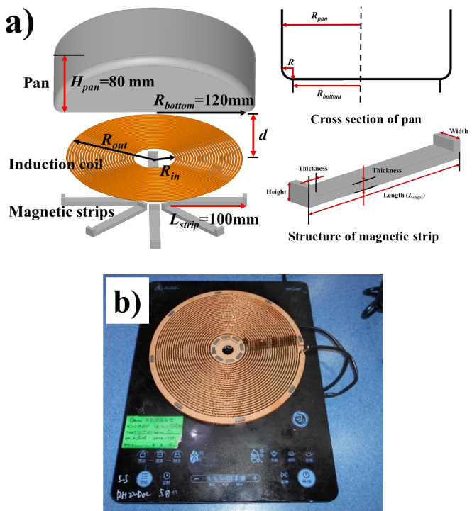
The 3-D model of the IH system (a) and the prototype (b) used in this work.
Model parameters
The induction coil is assumed to use Litz wire [22], which is commonly used in practical product, to alleviate the skin effect. The eddy current induced in the induction coil can be ignored in calculation. The magnitude of current flowing in the coil is 13 A× turns with the frequency of 20 kHz. To simplify the simulation process, the relative permeabilities (μ r ) and the electric conductivity (σ) of the magnetic strip, induction coil and pan used in this work are considered as the constants in this work [24].
The alternative current in the induction coil induces an alternative magnetic field around the coil, and the alternative magnetic field induces a current in the pan, which can be explained by the current law:
From Eq. (2), the induced current intensity in the pan is determined by the magnetic flux density that penetrates the pan.
A small cubic with dimension a × b × l is derived from the bottom of pan, as is shown in Fig. 2. The cubic is small enough in which the distribution of current density can be regarded as uniform one, thus the heat generates in the cubic can be calculated with Joule’s law:
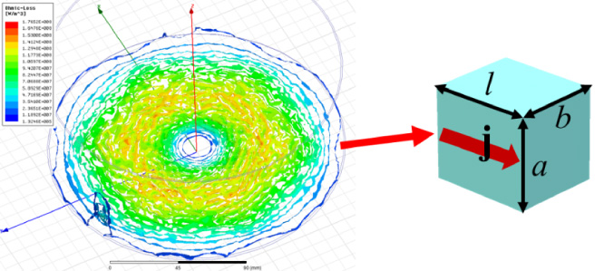
The distribution of joule loss induced by single turn coil (left) and a tiny cubic extracted from the bottom of the pan (right).
The heat dissipation condition of the selected cubic can be divided into three parts including the heat radiation which is only related to the temperature difference between pan and environment, the convection heat transfer which is influenced by the velocity of air flow around the pan, and the heat conduction that occurs between the glass panel and pot. In this work, the heat emission of pan is calculated with Newton’s law of cooling, which can be expressed by the equation:
The heat conduction within the pan can be calculated by Fourier’s law, and can be expressed by the equation:
So, the temperature increase of the cubic can be calculated with
Overall, the temperature distribution in the pan is decided by both the eddy current distribution and the heat dissipation condition in different positions. For an induction cooker working under a certain condition, the heat dissipation condition of the pan is fixed, so the temperature distribution is determined by the joule loss intensity in the pan, i.e., the distribution of induced current intensity in the pan. For a typical domestic induction cooker, due to the structure limitation of heating coil, the induced joule loss in the pan is uneven, as is shown in Fig. 2, which causes local overheating on the pan.
In this work, the uniformity of joule loss density in the pan is improved by adjusting the induction coil structure. By appointing thermal dissipation condition to the model, the temperature distribution can be calculated thus the influence of coil structure on the temperature distribution can be obtained. With the modification of the induction coil, more even joule loss in the pan is achieved. With further optimization of the induction coil, the temperature distribution in the pan is refined eventually.
Han et al. [14] suggested that if the induction coil and pan are divided into two parts, the heating uniformity can be improved. In this work, more detailed division is performed to adjust the coil structure more precisely. According to the number of coil segment, both the induction coil and pan are divided into 28 parts. Each coil segment is treated as an independent coil and numbered 1 to 28 from the coil center. The currents in different positions are controlled by varying the coil turns, so the current value in coil
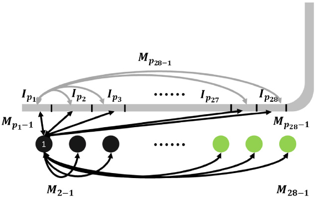
Mutual inductances between coil 1 and the different parts of induction coil and pan.
To investigate the relationship between the coil structure and the distribution of joule loss in the pan, a set of equations based on the principle of magnetic induction is expressed as:
The mutual inductance between two parts of pan i and j is marked as M
p
j
−i
, as is shown in Fig. 3. The current equation can be expressed as:
Also, since the coils are connected in series, the sum of V
i
equals to the voltage of the convertor:
By solving the equations above, a function between I p i and n j can be derived. By properly designing the coil structure, the variation of induced currents in different parts of the pan can be decreased, and as a result, the heat generation in the pan becomes more even, as explained by Eq. (6).
A prototype with the same structure as the model is fabricated to verify the simulation accuracy, as is shown in Fig. 1(b). Same as the domestic induction cooker, litz wire consists of 99 strands insulated electrically from each other and is embedded in a polymer base, L-shape magnetic strips is assembled under the base to prevent leakage of the magnetic field. The assembled induction coil is connected to the power circuit same with that in domestic products.
To measure the temperature distribution on the pan’s surface, the pan is dry-heated with room temperature of 25 °C and no wind. The deformation of pan becomes serious at high temperature, so the measured temperature is under 200 °C to prevent the pan from being damaged in experiment.
Results and discussion
Simulation and experimental results on single turn induction coil system
The distribution of induced magnetic field is determined by the coil structure [10,14]. We first investigated the single turn coil. The temperature distribution on the pan’s surface is measured with thermal imager and simulated with finite element method. Figure 4(a) shows the distributions of the induced magnetic field
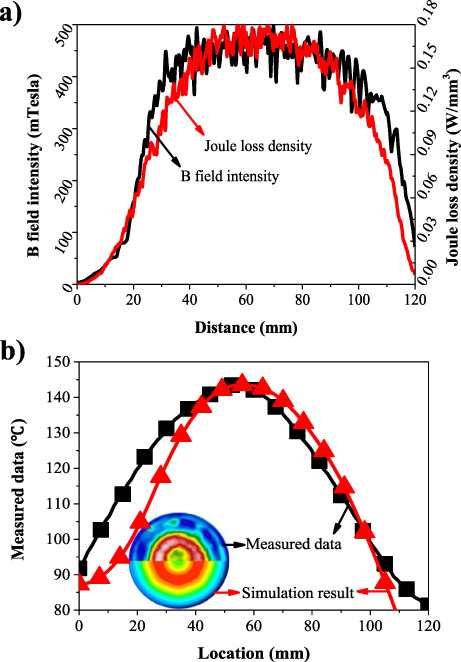
The distributions of the induced magnetic flux density B and Joule loss density on the pan (a) and the measured and calculated temperature distributions on the surface of the induction pan (b).
As expressed by Eq. (2), increasing the magnetic flux density B can increase the joule loss. It is known that the induced B intensity is inversely proportional to the square of the distance between pan and the induction coil. To increase the B intensity in the center and outer part of pan, more coils are added in the corresponding area in this work. Figure 5 shows the modified coil structure and the simulated results for the induced joule loss intensity along the pan’s radius. Assuming that the current in each coil have 4 values, there will be 428 models to analyze. To reduce the model amount, the coil segments are divided into 6 groups and numbered 1 to 6 from the coil center to the edge, and the cross section of coils are shown in Fig. 5 insets.

The modified on the inner part of induction coil structure (a,b) and outer part of induction coil (c,d).
To increase the induced joule loss in the center part, more coil turns are added to the group 1, as is shown in Fig. 5(a) inset. The simulation results indicates that by multiply the coil turns of group 1 coil, higher joule loss density in the center part is achieved while the joule loss intensity in the outer part is not influenced. To get more uniform joule loss distribution, more modifications are performed. Based on the structures of coil 2 and coil 3 in Fig. 5(a), new coils are designed by adding additional coil turns in each segment, as shown in Fig. 5(b), and their cross sections of coil structure are also shown in Fig. 5(b) inset. The results from Fig. 5(a) and 5(b) demonstrated that by adding coil turns in the inner part of the induction coil, the joule loss density induced in the inner part of pan can be increased, while the induced joule loss density in the outer part of pan is not influenced significantly.
Similarly, by adding coil segments of group 6, the induced joule loss intensity in the outer part is increased. The joule loss density along the radius and the cross section of coil are shown in Fig. 5(c). Also, more modifications are performed based on coil 9 and coil 10, and more uniform distribution of the induced joule loss in the pan is obtained with coil 15, as depicted in Fig. 5(d). By adding more coil turns in the outer part of the induction coil, the induced joule loss density in the outer part of pan is increased while the induced joule loss density in the outer part of pan is not influenced significantly. With the coil numbered 15 in Fig. 5(d), a platform pattern of joule loss density is obtained in the pan. Since joule loss is the only heat source considered in this work, the variation of heat generation power induced by coil 15 is small in a large area in the pan.
Figure 6(a) compares the distribution of induced joule loss density along the pan’s radius for the modified coil 15 in Fig. 5(d) and for the single turn coil. With the modified winding, the uniform distribution of induced joule loss along the radius is achieved in a large region. The temperature distributions in the pan using those two coils are shown in Fig. 6(b). For the single turn induction coil, the temperature distribution along the radius of pan have a single peak, which is agreement with the measured temperature shown in Fig. 4(b). It is clearly shown here that with the modified coil, more uniform temperature distribution is obtained in the pan.
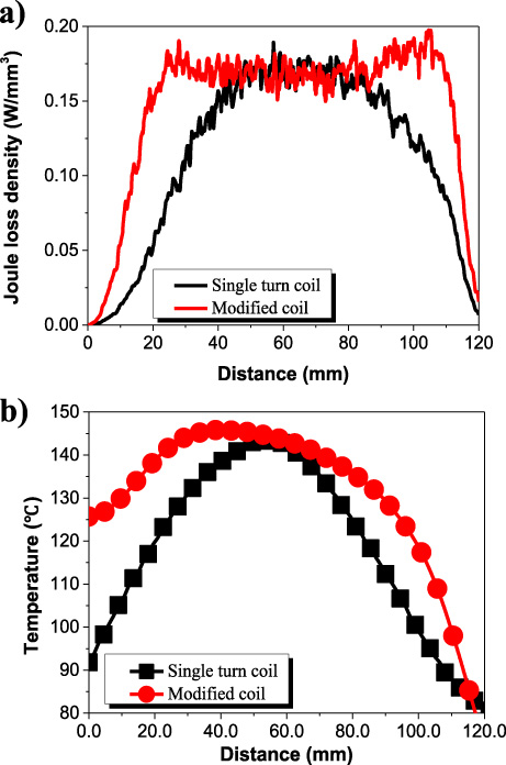
The joule loss along the radius for single turn coil and modified coil (a) and the temperature distributions along the radius of pan for single turn coil and modified coil (b).
Although the temperature distribution with the modified induction coil is more uniform than the single turn induction coil, there still exists overheating region around the position of R = 25 mm, as shown in Fig. 6. By adding or removing one coil turn at a time, more detailed refinement is carried out to get more uniform temperature distribution. Figure 7(a) shows the temperature distribution obtained by different induction coils depicted in Fig. 7(a) inset. The result indicates that the temperature distribution on the edge of pan is influenced significantly while the temperature in the inner part of pan is not influenced by adding or removing coil turn in the outer part of the induction coil.

The influence of coil structure on temperature difference (a) and RSD value of different induction coil (b) on the radius of pan between 20–100 mm.
Up to now, it is difficult to quantitatively evaluate the uniformity of the induction heating. In this work, we proposed a specific parameter named relative standard deviation (RSD) to define the temperature uniformity obtained by different induction coils. The RSD in a certain range along the radius of pan can be expressed as,
Using the RSD value, the temperature uniformity of induction cooker can be quantized, and the smaller value of RSD indicates better heating uniformity.

The temperature distribution on the pan with refined induction coil (a) and comparison between the single turn coil, refined coil and simulation result (b).
In this work, the refinement is carried out in the outer part of the induction coil, and its influence on temperature is also on the outer part of pan. Due to the limitation of round induction coil, the temperature value in the edge of pan is always lower than the other part. So, we use temperatures in the distance range of 20 mm to 100 mm to evaluate the temperature uniformity and the results are shown in Fig. 7(b). Lower the RSD value means smaller temperature variation in this region. The results show that, by refining the coil structure, more even temperature distribution on the bottom of the induction pan is obtained. The minimum RSD value is achieved with coil 7, which means coil 7 in Fig. 7 gives the best heating performance. Coils 3, 4, 10 and coils 5, 6. 7, 8, 9 have the same coil turns, the difference between them is the coil position. Figure 7 suggests that the temperature distribution on the pan is influenced both by the coil turns and coil position. The change of coil structure on the outer part of induction coil have significant influence on the temperature distribution.
The above simulation results indicate that by adjusting coil turns on different position of the single induction coil, more even joule loss density and temperature distribution in the pan can be achieved. The only difference between coils 7, 8, 9 is the position of a single coil turn, but temperature variation and RSD value of coil 8 are higher than the other two coils, which means the structure of uniform heating coil should be carefully designed.
Based on the simulation results, a refined induction coil is fabricated in this work assembled based on the structure of coil 7 shown in Fig. 7(a) (inset). The temperature distribution on the pan’s surface measured by thermal imager is shown in Fig. 8(a). When the temperature at the bottom of the pan exceeds 200 °C, obvious deformation will occur. Therefore, in the measurement process, the temperature at the bottom of the pan is controlled below 200 °C and the current in the simulation model is reduced to 7 A× turns. The result shows that with refined induction coil, the temperature distribution is still ring-like. More detailed temperature distribution is extracted and compared with simulation results, as is shown in Fig. 8(b). The difference between simulation result and measured data can be explained by thermal dissipation condition, but the measured result is in good agreement with the simulation one. The temperature distribution for single turn coil is also added in Fig. 8(b). With the refined induction coil, the variation of temperature is 20 °C, which is much smaller compared to 50 °C temperature variation with single turn induction coil. This result proves the method we proposed in this work that achieving uniform heating effect by adjusting the structure of induction coil is feasible and the simulation model employed in this work is valid. A low temperature area in the center part still exist due to the limitation of the coil structure, but it can be eliminated by increasing the radius of induction coil [25].
Hence, we use a simple method in this work to improve the heating uniformity by adjusting the structure of a single induction coil. Different from the other methods of improving heating uniformity by adding additional resonant coil, designing multi-coil system and mobile induction heating system, the present method is compatible with the power system, and the refined single coil is easy to realize for manufactures. Also, since the structure is simpler compared to many other designs, the performance of the present system with refined single coil is more reliable.
Conclusion
This work focused on improving the heating uniformity of domestic induction cooker with a single induction coil. A method to explain the relationship between induction coil structure and the temperature distribution in pan is proposed. Although eddy current is the main source of heat generation, the temperature distribution in the pan is determined by both eddy current distribution and heat dispute condition. To design a uniform heating induction coil, it is recommended to optimize the structure by investigating eddy current distribution in the pan, and then to refine the structure based on the temperature distribution in the pan considering heat dispute condition. The result indicates that adding coil turns at certain location can increase the temperature at the corresponding part of pan. For the induction coils with same coil turns, the difference in coil structure can eventually change the temperature in the pan. For this reason, the coil structure should be carefully considered in designing. Finally, the heating performance of the best refined coil is experimentally measured based on self-fabricated prototype. To compare heating uniformity of different induction coils quantitatively, an RSD value of temperature in a certain region is introduced. Both simulation and measurement results demonstrated that with the refined induction coil, the temperature variation on the pan is much smaller. Most importantly, the refined single induction coil is compatible with existing power circuit in the current industry. Hence, this work provides a predictable, cost-effective solution for the manufacturers to achieve homogeneous heating in the domestic induction cooker.
Footnotes
Acknowledgements
This work is partly supported by the FoShan ShunDe Midea Electrical Heating Appliances Manufacturing Company Limited and Sanqiaohui (Foshan) New Materials Co. Ltd. Yaxiang also thank the PhD scholarship and Post-doctor fellowship from South China University of Technology.