
Abstract
Magnetic gear has the advantages of less noise and vibration in non-contact driving and has a broad application prospect. To improve the magnetic gear’s torque performance, an improved double-flux-concentrating coaxial magnetic gear (DFC-CMG) is proposed in this paper. The DFC-CMG adopts arc-shape inner permanent magnets (PMs) and spoke-type outer PMs, which are embedded in the rotor iron yoke and tangentially magnetized along the circumference. In addition, to reduce the amount of iron, the outer rotor yoke periphery of the proposed model is slotted. The finite element method (FEM) is used to simulate conventional and improved models, respectively. The air gap magnetic field and electromagnetic torque of the conventional model and the improved model are calculated, and the harmonic content of the inner and outer air gap magnetic density is analyzed. Simulation results show that the torque density of the improved model is 34.6% higher than that of the conventional model, and the output torque ripple of the outer rotor of the improved model is reduced by 0.58% compared to the conventional model. This paper can provide some references for high-performance magnetic gears.
Introduction
Mechanical gears are widely used in industrial production as a significant transmission component [1]. However, the transmission of the mechanical gear system depends on the contact stress between the teeth, so there are some problems, such as friction loss caused by physical contact, noise, and vibration [2,3]. Because of this, the realization of contactless transmission of magnetic gear has attracted people’s attention [4]. Compared with conventional mechanical gears, magnetic gear transmission does not cause loss of mechanical friction, so it has less noise and vibration and does not require extra maintenance. In addition, since it is non-contact driven, if overload torque is applied, the magnetic gear can prevent overload by non-contact sliding. When the overload torque disappears, the gear teeth can be reconnected and recombined to operate normally [5–7]. Despite the above advantages of magnetic gears, in early studies, due to its single topological structure, the poor performance of permanent magnets, low torque density, and other characteristics, magnetic gears did not attract enough attention [8,9].
In recent years, with the continuous improvement of permanent magnets’ performance and the proposal of magnetic field modulation coaxial magnetic gear (CMG), the transmission performance of magnetic gear has been significantly improved, and more and more scholars have begun to pay attention to magnetic gear. So far, according to the principle of magnetic field modulation, various types of magnetic gears such as planetary gear, harmonic gear, linear gear, and axial gear have been proposed [10–14]. At the same time, the application of the Halbach array further improves the torque capacity of the magnetic gear and dramatically reduces the ripple of the output torque. The next step of the research on magnetic gear can focus on improving its torque density and practicability. From changing the shape of the adjusting magnetic ring to optimizing the parameters of the magnetic gear, how to improve the torque density of the magnetic gear has become a hot topic in this field [15–17]. Reference [18] proposed various shapes of flux-modulators and compared the transfer torque characteristics of coaxial magnetic gears using a nonlinear FEM based on a 2-D numerical analysis. The results indicate that the torque ripple of the magnetic gear is minimal when the flux modulator is designed to be circular. A new topological structure of double-rotor planetary magnetic gear was proposed in [19]. The two-dimensional FEM was used to simulate the magnetic gear with a transmission ratio of 14; the results show that compared with other high-performance magnetic gear topologies, the torque density was much improved. To increase the torque of the magnetic gear and reduce its torque ripple [20], put forward a dual-flux-modulator CMG. Through simulation and experimental analysis, it is concluded that compared with not introducing auxiliary magnetic flux modulator magnetic gear, the torque density of the proposed model has increased significantly, and the torque ripple has been effectively reduced. Reference [21,22] pointed out that the installation of spoke-type permanent magnets is beneficial to improve torque performance and reduce torque ripple. At present, the combination of magnetic gears and motors has many advantages and has been widely used in new energy fields such as pure electric vehicles, wave power generation, and wind turbines [23]. Therefore, it is necessary to study a magnetic gear with a lightweight, high torque density, and low output torque ripple.
In this paper, a structure of improved DFC-CMG is proposed. Based on the conventional structure of CMG, the PMs of the inner and outer rotors are improved, respectively. In the improved model, the inner PMs are arc-shaped embedded in the inner rotor iron yoke and magnetized along the circumference tangentially, while the outer PMs are spoke-type embedded in the outer rotor iron yoke and magnetized along the spokes tangentially. The improved model is analyzed by using two-dimensional finite element analysis software and compared with conventional magnetic gears in terms of magnetic force line distribution, air-gap magnetic harmonic content, static torque, steady-state torque ripple, and other aspects. Simulation results show that the improved model not only improved the torque transferability and the utilization rate of PMs but also reduced the torque ripple of the outer rotor.
The basic theory of magnetic gear
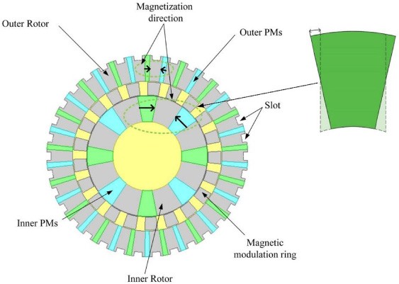
Figure 1 shows the topological structure of the conventional CMG. The conventional model is composed of the iron yoke of the inner and outer rotor, the inner and outer PMs, and the magnetic modulation ring. There is an air gap between the magnetic modulation ring and the PMs of the inner and outer rotors, respectively. The PMs are respectively fixed to the corresponding rotor iron yoke by the surface mount. The magnetization direction of the PMs is radial magnetization, and the magnetization direction between adjacent permanent magnets is the opposite.

Topological structure of conventional CMG.
The air gap magnetic field of the coaxial magnetic gear is jointly generated by the permanent magnets of the inner and outer rotors. To facilitate the analysis of the air-gap magnetic field, it is assumed that all magnetic circuits of the magnetic gear are linearly unsaturated; the magnetization of the permanent magnet rotor is sinusoidally distributed along the circumferential direction, and the magnetic permeability of the rotor yoke is infinite. By taking the scalar magnetic potential as a variable and establishing the Laplace and Cauchy–Poisson equations in the computational domain, the radial and tangential magnetic flux densities generated by the inner permanent magnet rotor alone can be expressed as:
p 1 and ω1 are the number of pole pairs of the inner rotor permanent magnet and the rotational speed of the inner rotor, respectively; R 1 and R 2 are the inner and outer radii of the inner rotor permanent magnet poles, respectively; R 3 is the inner diameter of the iron yoke of the outer rotor; θ a is the initial value of the inner rotor angle; r and θ are the polar moment and phase angle of the measuring point in polar coordinates respectively; the coefficients A and B are only related to the polar moment r and have nothing to do with the phase angle θ.
The radial and tangential magnetic flux densities generated by the outer permanent magnet rotor alone can be expressed as:
p 2 and ω2 are the number of pole pairs of the outer rotor permanent magnet and the rotation speed of the outer rotor respectively; R 3 and R 4 are the inner and outer radii of the outer rotor permanent magnet poles respectively; θ b is the initial angle of the outer rotor; the coefficients C and D are also only. It is related to the polar moment r but not to the phase angle θ.
After the magnetic control ring is introduced, the air gap space is divided into an inner air gap and an outer air gap by the magnetic control ring. Since the magnetic permeability of the magnetic control block is much larger than that of the air, the magnetic flux density in the air gap changes. From a qualitative point of view, the introduction of a magnetically tunable block can be equivalent to multiplying the magnetic field distribution of an unregulated magnetic block by a permeability function, that is,
B
o
is the magnetic field strength when there is no magnetic control ring; B
M
is the magnetic field strength after the magnetic control ring is introduced; 𝜆∗ is the complex permeability function of the two-dimensional magnetic circuit. In polar coordinates, it can be further expressed as
𝜆
a
and 𝜆
b
are the radial and tangential components of the complex permeability function, respectively. The radial and tangential components of 𝜆∗ in the inner air gap can be expressed by Fourier series respectively as
In the same way, the radial and tangential components of 𝜆∗ in the outer air gap can be expressed by Fourier series respectively as
In the formula, N s is the number of magnetic control blocks in the magnetic control ring; 𝜆 o _in , 𝜆 o _out , 𝜆 ak _in , 𝜆 ak _out , 𝜆 bk _in , 𝜆 bk _out are Fourier coefficients.
Substituting Eqs ((7))--((10)) into Eqs ((5)), it can be seen that the magnetic flux density generated by the inner air gap of the permanent magnet inner rotor can be expressed as
The magnetic flux density generated by the permanent magnet inner rotor in the outer air gap can be expressed as
Similarly, the magnetic flux density generated by the permanent magnet outer rotor in the inner air gap can be obtained as
The magnetic flux density generated by the permanent magnet outer rotor in the outer air gap is
The magnetic modulation ring is the most crucial part of the CMG, and there are uniformly distributed magnetic modulating blocks on the magnetic modulating ring. The number of magnetic modulating blocks and PMs satisfies the following relationship:
The modulator ring mainly affects the inner and outer air gap magnetic fields, so that inner and outer air gap magnetic fields can be effectively coupled and produce the corresponding torque. The magnetic fields generated by the inner and out PMs are modulated by the modulation ring, the harmonic contained in the air gap magnetic fields can be expressed as:
The harmonic components in the air gap of the inner and outer rotor have a certain number of polar pairs and rotational speed. The angular velocity of each spatial harmonic component contained in the inner and outer air gap is:
Equations (20) and (21) represent the spatial harmonic distribution of the air gap magnetic field and the rotational speed of the harmonic magnetic field, respectively, and the gear ratio of the magnetic gear can be obtained according to the two equations.
From Eq. ((21)), when there is no magnetic modulation ring, it means that k = 0, the angular velocity of the spatial harmonic component is the same as the angular velocity of the inner or outer rotor; when the magnetic modulation ring is introduced, it means that k ≠ 0, the rotational speed of the spatial harmonics in the air gap is not equal to the rotational speed of the rotor. According to the law of electromechanical energy conversion, it can be known that only two magnetic fields have the same pole pair number, and energy can be transferred between them. Therefore, the number of magnetic pole pairs on another rotor should be the polar logarithm of a spatial harmonic when k ≠ 0. When m = 1, k = −1, the magnitude of the spatial harmonics is the largest [24], and the number of pole pairs of the other rotor must be equal to (n
s
− p) to transmit torque as much as possible. when Ω
s
= 0, it means that when the magnetic modulation ring is stationary, the transmission ratio of the magnetic gear can be obtained as:
The spoke-type permanent magnet installation is beneficial to the electromagnetic performance of the magnetic gear. Figure 2 shows the improved topological structure of DFC-CMG. In order to increase the coupling area of the magnetic fields of the inner and outer rotors, the structure of the spoke permanent magnets is adjusted in this paper, and the method of arc-shaped embedded spoke permanent magnets in the inner rotor iron yoke is adopted. The inner PMs are arc-shaped, embedded in the iron yoke of the inner rotor, and magnetized along the circumference tangentially. The outer PMs are spoke-type embedded in the iron yoke of the outer rotor and magnetized along the spokes tangentially. The adjacent PMs of the rotor are magnetized in opposite directions, forming a flux-concentrating N-S-N structure. Compared with the conventional model, the PMs of the improved model are embedded in the rotor iron yoke. Therefore, the phenomenon that the PMs of the conventional model are easy to fall off can be effectively avoided, and the mechanical strength of the magnetic gear is also improved. Torque density is an important parameter index to measure the magnetic gear, which refers to the output torque of the magnetic gear per unit volume.
Topology of an improved double-flux-concentrating coaxial magnetic gear.
To reduce the amount of iron, the slotting method can reduce the volume of the magnetic gear, thereby achieving the purpose of increasing the torque density. According to the distribution of magnetic lines, it is considered to slot on the periphery of the outer rotor where the magnetic lines are less to ensure the output of torque and the coupling of the magnetic fields of the inner and outer rotors. And the small-size rectangular slotting method can also ensure the mechanical strength of the rotor during operation. Therefore, the transfer of torque after slotting will not be negatively affected.
In this paper, the coaxial magnetic gear with the transmission ratio of 17:4 is modelled and analyzed. The specific parameters of the magnetic gear proposed are shown in Table 1.
Specific parameters of the improved model
To make the conventional model comparable with the improved model, the primary structural parameters of the two models must be the same. The finite element analysis software analyzes the magnetic field distribution and torque capacity of the two models.
Comparison of the original model and improved model
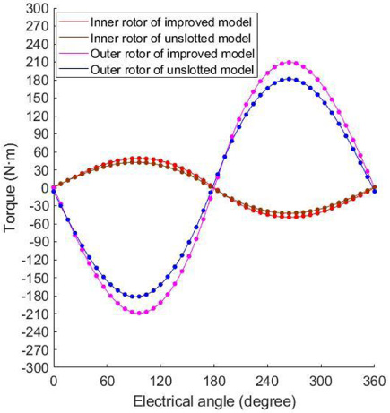
First, we need to explain the necessity of slotting the iron yoke of the outer rotor in the improved model. Figure 3 shows the topological structure of the original and improved models. Figurer 3(a) is the original model before the slotting and Fig. 3(b) is the improved model after the slotting of the iron yoke of the outer rotor. In the original model, there are some magnetic field lines on the outside of the outer rotor. It illustrates that there is a certain magnetic leakage phenomenon, which will lead to a decrease in the utilization rate of the permanent magnets. In the improved model after the outer rotor iron yoke is slotted, because the air reluctance in the slotted area is larger, the magnetic flux leakage phenomenon is reduced. The slotting method improved the utilization rate of the permanent magnet and the torque performance. Figure 4 shows the static torque comparison of the two models. It can be seen from the figure that the static peak torque of the slotted model is higher than that of the original model. It can be concluded that although the slotting of the original model will increase the complexity of the manufacturing process to some extent, the weight of the improved model will be reduced and the torque performance will be greatly improved.
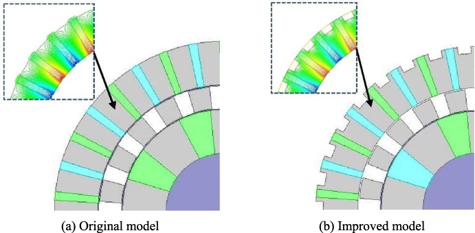
The structure of the two models.
The static torque of the two models.
Figure 5 shows the distribution of magnetic lines of the two models. From the comparison of magnetic lines, there are 8 wave heads on the inner rotor of the two models, which is consistent with the 4 pairs of magnetic poles of the inner rotor. Part of the magnetic lines generated by the inner PMs form a loop with the adjacent PMs, and the other part is coupled with the magnetic field established by the outer PMs to generate the corresponding torque. There is a part of magnetic leakage in the non-magnetic material. As can be seen from Fig. 5(b), there are few closed magnetic lines formed on the periphery of the outer rotor yoke before slotting. Therefore, slotting in Fig. 5(b) does not affect the transfer of torque. After slots, the quality of the magnetic gear was reduced, and the torque density was improved.
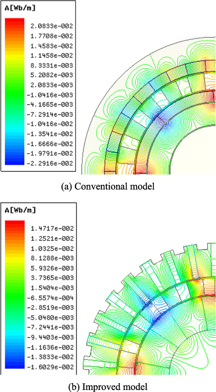
Distribution of magnetic lines.
Figure 6 shows the radial and tangential flux density waveforms of the inner air gap after calculation by the finite element method. From Fig. 6(a) and 6(b), we can see the effect of the inner rotor permanent magnets with 4 pairs of pole pairs. Although the presence of the modulator causes many magnetic spikes, four complete magnetic field cycles can be observed. It can be seen from Fig. 6(c) and 6(d) that both the radial and tangential flux density component amplitudes of the improved model are higher than those of the conventional model. The air-gap flux density is not only the key hub of magnetic gear transmission but also its torque and torque ripple are directly affected by the number and size of harmonic waves of the air-gap magnetic field. The harmonic spectrums are shown in Fig. 7 and Fig. 8.

Comparison of flux density waveforms.

Harmonic spectra of flux density in inner air-gap.
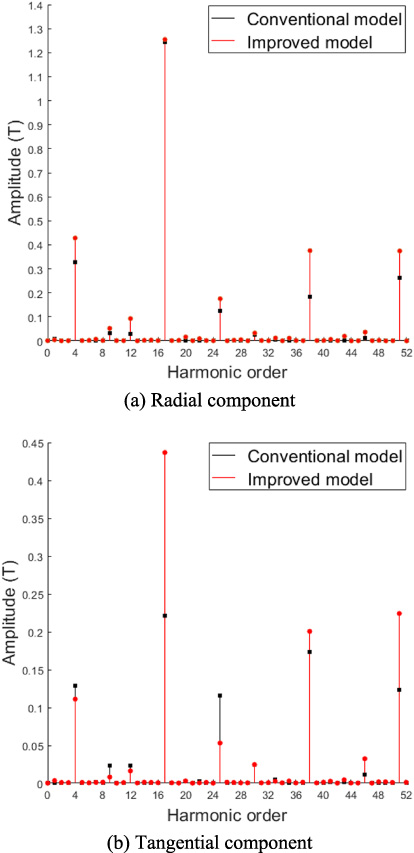
Harmonic spectra of flux density in outer air-gap.
Figure 7 shows the harmonic spectrum of the inner air gap space. Under the action of the modulation ring, a large number of harmonics are introduced into the inner air gap magnetic field. It mainly contains 4, 12, 17, 20, 25, 28, 33, 36, 38, 41, 46 harmonics, the largest amplitude is the 4th harmonic, and it is the highest harmonic generation of torque. According to the analysis, the harmonic order of 12, 20, 28, 33, 36, 41 do not participate in the transmission of torque, and part of them are the factors causing torque ripple, while the harmonic order of 4, 17, 25, 38, 46 have a positive impact on the generation of torque. As can be seen from Fig. 6, compared with the conventional model, although the radial component amplitude of the 4 harmonics decreased slightly in the improved model, the amplitude of 17, 25 harmonics increased. Besides, the tangential component amplitude of the 4, 17 harmonics significantly increased, and the amplitude of the 25, 38, and 46 harmonics decreased to some extent.
Figurer 8 shows the harmonic spectrum of the outer air gap space. It can be observed that the outer air gap mainly contains harmonics of 4, 12, 17, 25, 38, and 51. The amplitude of the 17 harmonics is the largest, which is the basic harmonic in the outer air gap. By comparing the two models it can be concluded that the amplitude of the 17 harmonic tangential components of the improved model has been dramatically increased, and most other harmonic amplitudes that positively affect the transmission torque have also been increased.
Static torque is an important parameter to measure the magnetic gear. When the load torque exceeds the peak torque of the magnetic gear, the inner and outer rotors of the magnetic gear will no longer drive according to the established transmission ratio, so the static torque determines the maximum load torque that the magnetic gear can bear.
Figure 9 shows the static torque curves of the two models, it is obvious that the static torque waveforms of the two models are sinusoidal waves, and the torque reaches its peak when the electric angle is 90°. According to the simulation data, the inner rotor torque of the conventional and improved model is 36.69 N⋅m and 49.15 N⋅m, respectively. The outer rotor torque of the conventional and improved model is 155.56 N⋅m and 209.34 N⋅m, respectively. It is concluded that the rotor torque of the improved model is about 34.57% higher than that of the conventional model. At the same time, the phase difference between the inner rotor torque waveform and the outer rotor torque waveform is half a period, in other words, at any time, the output torque of the inner and outer rotor is opposite, and the ratio of the inner and outer torque is approximately equal to the transmission ratio of the magnetic gear.

Static torque-angle curve.

Steady-state torque curve.
Torque ripple represents the stability of magnetic gear transmission and is an important parameter to measure the performance of magnetic gear transmission.
Figure 10 shows the steady-state torque of the two models, the rotational speeds of the inner and outer rotors in the two models are 1700 r/min and 400 r/min, respectively. It can be intuitively drawn from the picture, the steady-state torque ripple of the inner rotor of the improved model is slightly larger than that of the conventional model. However, the steady-state torque ripple of the improved outer rotor of the model is lower than that of the conventional model due to the total amount of permanent magnets of the improved model is slightly lower than that of the conventional model.
Table 2 shows the specific parameters given by the simulation results for torque ripple. It can be seen from Table 2 that the steady-state torque of the improved model rotor is much larger than the conventional model. And the difference in torque ripple needs to be analyzed from a numerical point of view. 𝛼 is defined as the torque ripple amplitude, which is expressed as:
Parameters of torque ripple
Table 3 compares the parameters of the two models. It can be concluded from Table 3 that the improved model has fewer PMs than the conventional model, but the torque density of the improved model is 34.6% higher than that of the conventional model, which means that the improved model permanent magnet utilization rate is much higher than the conventional model. Also, since the peripheral iron yoke of the improved model is slotted, the overall quality of the magnetic gear is degraded, and the torque density is improved.
Quantitative comparison among two MGs
In the paper, we propose an improved DFC-CMG for the problem of low torque density, the low utilization rate of PMs, and the insufficient mechanical strength of the conventional model. The FEM is used to calculate the air gap magnetic field and electromagnetic torque of the conventional model and the improved model, respectively. The simulation results show that the inner torque of the improved model increases from 36.69 N⋅m to 49.15 N⋅m, and the outer torque increases from 155.56 N⋅m to 209.34 N⋅m compared with the conventional model. It means that the torque density of the improved model is 34.6% higher than that of the conventional model. At the same time, the number of permanent magnets in the improved model is less than that of the conventional model, which means the permanent magnet utilization of the improved model is much higher than that of the conventional model. In addition, the output torque ripple of the outer rotor of the improved model is reduced by 0.58% compared to the conventional model, which means that the size of the outer torque ripple of the improved model is reduced by about half compared to the conventional model. The improved model can effectively improve the torque density and permanent magnet utilization and reduce output torque ripple of the outer rotor, which can provide some reference for the high-performance magnetic gears.
Footnotes
Acknowledgements
This work was supported by the National Natural Science Foundation of China (Grant no. 51765020).
Conflict of interest
On behalf of all authors, the corresponding author states that there is no conflict of interest.