
Abstract
A multi-frequency planar electromagnetic generator is proposed to harvest energy from low-frequency vibrations efficiently in a wide frequency range. The vibration energy harvester is composed of two single-degree-of-freedom resonant systems with different natural frequencies. Two permanent magnets are used as single-degree-of-freedom spring mass to respond to external vibrations, and controlled by another permanent magnet with magnetic attraction. In addition, ferrofluid adsorbed on the poles of two moving permanent magnets can reduce the damping significantly to improve the utilization of low-frequency micro vibrations. Experiments show that, during human walking and jogging, the fabricated generator can obtain 1.3718 mW and 1.4227 mW output power, respectively.
Introduction
Microelectronics and wireless sensors technologies have brought great convenience to human life and widely increased range of human activities [1]. Such low power electronic devices are usually powered by batteries in their various forms [2]. However, due to the limitation of battery life, replacement and the environment pollution of discarded batteries, more research works have been done to replace batteries with other alternative power sources [3]. An efficient way to address this limitation is harvesting electrical power from ambient vibrations and form a self-powered system. One of the most convenient kinds of vibration energy is the low-frequency vibration with lower energy density and wide frequency range, which makes a new challenge in the energy harvesting technology. It is known that there are four mainstream types of conversion mechanism: electrostatic, piezoelectric, magnetostrictive and electromagnetic [4]. Some works have been done to improve the efficiency of vibration energy harvesting, such as combination of many energy conversion mechanisms, integration of resonance frequency and improvement of vibration response ability.
ZdenekHadas [5] used two piezoelectric modules to form a piezoelectric vibration energy harvester with two degrees of freedom, which broadens the working resonance bandwidth. Ye-Wei Zhang [6] employed a laminated structure to place the piezoelectric layer between two magnetostrictive layers to achieve high-voltage output in a wide frequency range. Due to the advantages of the electromagnetic energy harvester, simple structure, high output power and power density, this type of generator has been the most noteworthy method [7]. Tra Nguyen Phan [8] found that the non-linearity electromagnetic energy harvester is better than the linearity by comparing the harvesting performance of electromagnetic energy harvester and that the non-linearity generator can be applied to high-level acceleration conditions. Ning Yu [9] discussed and verified the influence of the mass ratio and damping ratio of the two-degree-of-freedom system on the electromagnetic acquisition performance. However, the traditional electromagnetic generator always has the problems of high mechanical damping and single collection frequency. SoonjaePyo [10] combined the piezoelectric and electromagnetic energy harvesting methods to acquire multiple resonance frequencies to increase energy output. Muhammad Masood Ahmad [11] built a dual-resonance electromagnetic energy harvester. In actual experiments, the power collected at the two resonance frequencies can bring to 0.13 mW and 0.18 mW.
To reduce the friction loss of the PM in motion in the electromagnetic energy harvester, we take the advantage of ferrofluid to reduce the damping of the second order single degree of freedom system [12,13]. What is more, a dual-resonance electromagnetic energy harvesting structure is chosen to broaden operating frequency bandwidth for a higher energy output. In this paper, we design a multi-frequency electromagnetic vibration energy harvester based on ferrofluid and analyze its correlation performance.
Structural design

Structural model of electromagnetic energy harvester.
As is shown in Fig. 1, the novel electromagnetic energy generator is composed of four coils, two moving permanent magnets (PMs) with ferrofluid, a fixed PM, adjustable nut and bolt, and shell. The two moving PMs are placed within the cages at the both ends of the shell, where the PMs can move horizontally in any directions along the bottom surfaces of the cages. The shell is designed a columnar structure with diameter of 52 mm and height of 90 mm. It is known that the ferrofluid can suspend PMs based on the principle of second-order buoyancy of ferrofluid, shown in Fig. 2. Once the moving PMs attract the ferrofluid, they will be suspended to avoid direct contact with the inner surfaces of the cages. The fluid-magnetic pressure P
m
can be obtained by the following Eq. (1). During the movement of PMs, due to the suspension force, the ferrofluid plays a role of lubricating and reducing wear.

Permanent magnet with ferrofluid.
In a single-degree-of-freedom spring mass vibration system, the traditional way of providing restoring force relies on mechanical springs, which are replaced by magnetic springs formed by the attractive force between the fixed PM and the moving PMs in this structure. Obviously, the stiffness of the magnetic spring is determined by relationship function between displacement and magnetic attractive force. Since the frequency is determined by the stiffness, two resonant frequencies can be obtained by choosing different specifications for the upper and lower moving magnets. As the fixed PM was placed on the nut, the distances between the PMs can be changed by adjusting the nut to realize the various stiffness of the magnetic springs. Therefore, the natural frequencies of the double-layer energy harvesting structure can respond to vibration in a wider frequency range and achieve multi-frequency vibration energy acquisition.
The external excitation acting on the shelf will force the moving PMs to slide on the plane of the cages, so the induction coils on the external ends of cages will produce electricity according to the Faraday’s Law of Electromagnetic Induction. The electricity generated can be stored and provided for the load. Some primary parameters of this generator are shown in Table 1.
Structure parameters of the electromagnetic generator
The vibration pick-up system of electromagnetic energy generator can be equivalent to a parallel single-degree-of-freedom system [15], shown in Fig. 3.

Physical model diagram of the parallel single-degree-of-freedom system.
Where
According to the principle of electromagnetic induction, connecting all induction coils in series, the induced voltage is [17]:
Magnetic attraction force and its affect
The fixed PM can decide the frequency range of the harvester by adjusting the distance from the moving PMs. Here, three cases are discussed with a constant distance 85 mm between two moving PMs, shown in Table 2.
The PMs spacing in different cases
The PMs spacing in different cases
Note: a: set the distance between the fixed PM and the upper moving PM as d 1; b: set the distance between the fixed PM and the lower moving PM as d 2.
A spiral test frame is designed and assembled with digital push-pull gauge and calibrated scale to obtain the relation between the distance and the restoring force, shown in Fig. 4.
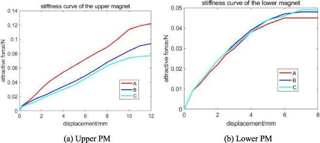
Stiffness measurement curves for multi-frequency energy harvesters.
According to Fig. 4, the stiffness of the magnetic spring in every case can be obtained from the slope of each curve. Therefore, knowing the stiffness and the mass of the moving PMs, the resonance frequencies of different cases can be determined by
When changing the distance between the fixed permanent magnet in the middle and the moving permanent magnets at both ends, the stiffness of the upper end of the magnetic spring changes a lot, representing a large range of its own inherent frequency. The more stable change in the stiffness of the lower end magnetic spring indicates that it corresponds to a more fixed vibration frequency. Usually, in a working condition, there will be a primary vibration frequency and several secondary vibration frequencies with a wide range of frequencies. Therefore, it is necessary to change the resonant frequency of upper system while keeping the intrinsic frequency of lower system constant.
Figure 5(a) shows the magnetic flux density vector diagram and cloud diagram of three PMs. The fixed PM offer the necessary recovery force for the PMs at both ends. Except for the magnetic attraction between the fixed and moving PMs, if there is a magnetic attraction force between the moving PMs, it may affect the response status of whole system. To prove the absence of interaction, the magnetic force between them with different distances is simulated, as shown in Fig. 5(b). Simulation result displays that the force is close to zero when the vertical distance is 83 mm. Thus, there is no influence.
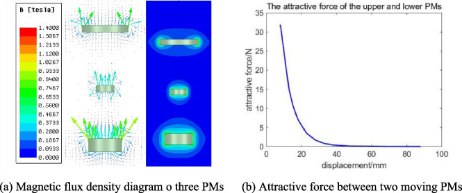
Magnetic flux density and magnetic attraction simulation results.
The damping of generator composes of two parts. One is the mechanical damping due to the friction, and the other is the electromagnetic damping caused by Lorentz Force. The damping value can be obtained by developing a flick test (flicking suddenly the movable PMs and monitoring the decay of the vibration amplitude over time). As for related damping 𝜉(=ln(R 0∕R n )∕(2πn)), it can be determined by the first peak amplitude R 0 and the n-th period peak amplitude R n .
Mechanical damping (𝜉 m ) and total damping (𝜉) are measured without load (open circuit), and with load (closed circuit), respectively. While electromagnetic damping (c e ) can be obtained by the difference between them. Table 3 shows the magnitude and trend of the three kinds of damping in different cases.
Damping data of the system
Damping data of the system
It can be seen that the mechanical damping and total damping gradually decrease with the cases changing from A to C. It results from the axial magnetic attraction between the fixed PM and the moving PMs. As the distance between the upper moving PM and fixed PM increases, the magnetic attraction acting on the upper moving PM will decrease. Instead, the suspension force of ferrofluid will lift the moving PM upward and reduce the contact area with the cage. The same applies to the lower moving PM, where the mechanical and total damping gradually decrease as the contact area between the moving PM and the cage increases. Although the electromagnetic damping is less than 15% of the total damping, the mechanical damping and the electromagnetic damping are basically in the same order.
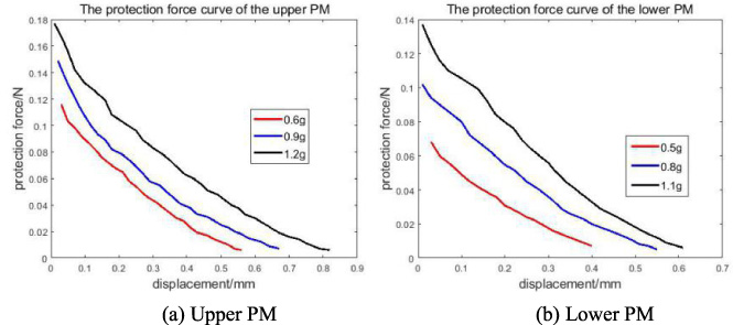
The ferrofluid adsorbed on the moving PMs also act as a buffer and protect the PMs from direct collisions with the inner surfaces of cage. Figure 6 shows the relationship between distance (suspension height of PMs) and protection force for different injection amount of ferrofluid. In the initial stages, the more ferrofluid, the greater protection force. Besides the injection amount of ferrofluid, the ferrofluid protection force is related to the saturation magnetization the strength of ferrofluid and the magnetic induction strength of permanent magnet. When the upper and lower PMs are injected ferrofluid with 1.2 g and 1.1 g, respectively, ferrofluid can provide the protective force of 0.18 N and 0.14 N to them in the limit state that the moving PMs will collide with the inner surfaces. The force can effectively bounce the PMs under the walking and jogging.
Output voltage and acceleration.
The multi-frequency planar electromagnetic generator was fastened on the waist of human to harvest energy from human walking or jogging. In the same time, the accelerometer (AD100T) is also tied to the waist to measure the acceleration. Figure 7 provides the output voltage and human moving acceleration measured by the dynamic signal collector (MPS-140801) for the case A.
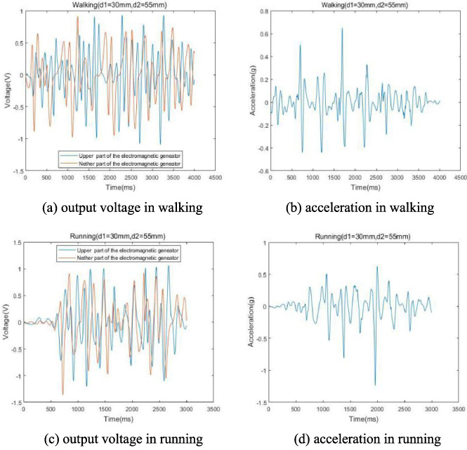
Output voltage and acceleration.
The figures show that more electrical energy is collected at the upper system in the walking pattern; while in the jogging mode, the opposite happens. This also indicates that the intrinsic frequency points at the upper and lower systems are closer to the vibration frequencies generated during walking and jogging, respectively. Therefore, this double-layer energy harvester can realize effective energy harvesting for more complex multi-frequency vibration and output more power than a single generator. In addition, due to the presence of ferrofluid, the PMs never collides directly with the inner wall throughout its movement.
The output power in each situation
Table 4 lists the output power of generator calculated from the output voltage and the external load in six situations. It can be seen that the maximum output power point is obtained in case B with power values of 1.3718 mW and 1.4227 mW. This behavior shows that the inherent frequencies of generator are closer to the waist vibration frequencies of human motion in the case B. The power bulk density and power mass density of generator in the walk mode are 1.74 μW/cm3 and 10.72 μW/g; and 1.80 μW/cm3 and 11.90 μW/g for the jogging mode. Since the trend of output power is first increasing and then decreasing in the process from case A to case C, the waist vibration frequency range is between A(3.9 Hz) to C(2.6 Hz) and closer to B(3.2 Hz–3.5 Hz). It can also be known from the acceleration diagram. Therefore, this vibration energy harvester can match these kinds of vibration frequencies to achieve a higher harvesting efficiency.
In this paper, a multi-frequency planar electromagnetic generator with ferrofluid and magnetic spring is proposed, including design, modeling, simulation, damping experiments, and energy harvesting experiments. The purpose of the structure proposed is to improve the response of harvester to low-frequency micro vibrations, including sensitivity and stability, by using the properties of the Ferrofluid, so that the output power of the electromagnetic energy harvester will be more adequate. By doing theoretical calculations and experimental measurements on the frequency of harvester, the magnetic springs with variable stiffness extend the operating frequency bandwidth range to 2.6 Hz–3.9 Hz. The wide frequency harvesting capability enhances the energy output power. Human motion energy harvesting experiments show that the maximum output power in two patterns of walking and jogging are 1.3718 mW and 1.4227 mW, respectively, and that the power bulk density can reach 1.74 μW/cm3 and 1.80 μW/cm3. It is able to supply energy to portable wireless sensing devices on the human body. This structure can be extended to more layers to match lots of intrinsic frequencies. Based on these, multi-layer energy generators can realize vibration energy harvesting in a wider range frequency and output more energy. In addition, the electromagnetic energy harvester can be applied to other vibration conditions, such as wave energy harvesting and bicycle vibration energy harvesting. Besides, there are some shortcomings in this paper: (1) the optimal size is not determined and the structure can be continued to be optimized; (2) the output energy is not collected by power management circuit, which can be investigated in further experiments later.
Footnotes
Acknowledgements
This work has been supported by Foundation of Key Laboratory of Vehicle Advanced Manufacturing, Measuring and Control Technology (Beijing Jiaotong University), Ministry of Education,China.