
Abstract
With the rapid development of UHV power transmission and transformation project in our country, the gradually increasing electromagnetic capacity and electromagnetic loads of power transformers causes serious heating of the transformers. Therefore, it is particularly important to accurately calculate its temperature rise. Based on field-circuit coupling method, this paper took a 240000 KVA, 330 KV power transformer as the research object to calculate the whole temperature rise and heat transfer characteristics. Firstly, the average velocity of fluid was gotten by three-dimensional flow field of transformer which is calculated by establishing thermal network model of the transformer, phase winding and related structures. And then substitute it into thermal network model. The whole average temperature and temperature rise was gotten by using first law of thermodinamics and after the iteration. And according to the temperature rise test, this paper comprised and analyzed the computed results of thermal network and numerical analysis. Results showed that the error of the thermal network model was within the scope of the permit, and it was simple and quick. The method can provide basis for the future heat transfer research and temperature rise prediction of transformer.
Introduce
Power transformer is one of the main electrical equipment in the power system. Its safe and reliable operation has a great impact on the overall security and stability of the power system [1–3]. With the increase of transformer capacity and electromagnetic load, the problem of temperature rise of transformer is particularly prominent in recent years. Therefore, the temperature rise of transformer has been paid more and more attention in recent years [4–7].
Scholars have done a lot of research on the temperature rise of transformer, and achieved rich results [8–12]. Jiangtaosha established an equivalent heat path model based on the bottom oil temperature, calculated its hot spot temperature, and verified the effectiveness of the method through experiments [13]. Tengli established an improved model of dynamic equivalent heat path of transformer, calculated the top oil temperature and winding hot spot temperature, and verified it by test data [14]. Chen weigen established a prediction model of transformer winding hot spot temperature based on genetic optimization support vector machine. Through experimental analysis, it is concluded that the calculation result of the model is superior to Elman neural network and BP neural network [15]. A Elmoudi simplified the thermal path model, and the hot spot temperature of transformer winding is calculated, and its applicability in temperature on-line monitoring system is verified by test [16]. Sachin B fully considered the influence of cooler on the heat dissipation of transformer, analyzed and modeled the internal flow and cooling state of transformer under the conditions of horizontal blowing and vertical blowing [17]. Xie Yuqing proposed a multi physical field coupling finite element method to calculate the winding temperature rise, solved the field temperature with the upwind finite element method, compared the calculation results with the results of FLUENT software, and verified the validity of the model [18].
Most of the research results are concerned about the local hot spot temperature of the transformer, but the influence of each part in the transformer is not fully considered. In this paper, the field circuit coupling is used to calculate the temperature rise in the whole area of power transformer. The average velocity of fluid is calculated by three-dimensional model. Then, according to the structure of transformer and related heat transfer theory, the whole area thermal network model of oil immersed transformer is established. According to the first law of thermodynamics, the energy flow equation of each node is given, and the temperature and temperature rise of transformer are obtained by iteration.
Calculation of flow field in transformer
As an important pivotal element in the power grid, the stability of large oil immersed transformer is directly related to the safety of power grid operation. The statistical data of transformer operation accidents show that most of the end of transformer life is caused by the high temperature of transformer winding hot spot, and due to the special structure of large power transformer, it is very difficult to accurately calculate the transformer temperature. Therefore, the hot spot temperature of transformer can not be ignored. How to effectively reduce it to the safe range is of great significance.
The mathematical model of fluid field
Transformer oil can be regarded as incompressible fluid approximately. The flow should follow the laws of conservation of mass, momentum and energy [19].
Oil circuit analysis
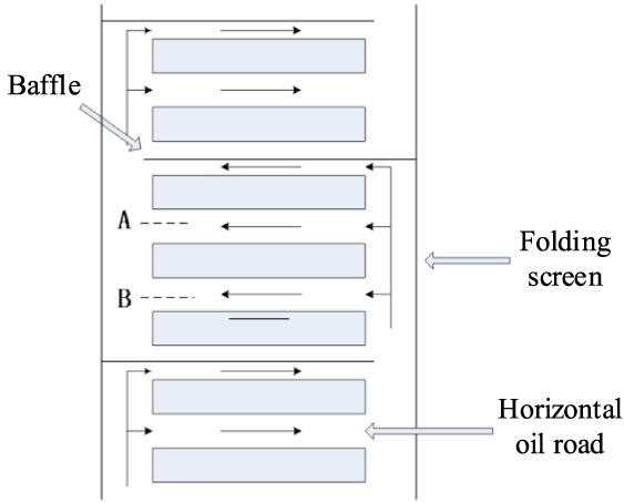
Figure 1 is the schematic diagram of the oil circuit of the winding. The cooling oil channel of the winding includes the vertical oil channel between the winding and the enclosure and the horizontal oil channel between the wire cake and the insulating pad. Due to the alternate blocking effect of the baffle, the oil flow in the vertical oil channel flows into the horizontal oil channel, which can take away the heat emitted by the winding and avoid the “dead oil area”.
Local winding oil channel.
In this paper, taking a SFPSZ11-240000/330 is used as the prototype, the dimension parameters are shown in Table 1 and Table 2.
The core parameters
The core parameters
The winding and folding screen parameters
The overall structure of the core area of the prototype is shown in Fig. 2.

The overall structure diagram of the core area.
In this paper, the transformer is a three-phase five column structure, and its three phases are completely symmetrical. The iron core and yoke are made of laminations, and the iron core and yoke are directly connected. The clamps on the iron yoke are used to clamp the upper and lower iron yokes, while the pull plate is used to connect the upper and lower clamps. The transformer is filled with transformer oil to conduct heat.
In the calculation of the winding flow field, because the winding is completely symmetrical along the axial center, the overall model of the winding oil circuit is simplified. The whole winding model is divided into 8 sections by oil baffle, and the structure of the first and last 4 sections is the same, and the height of wire cake is 13.15 mm. The structure of the middle 4 segments is the same, and the height of the wire cake is 13.75 mm, and 1∕16 of the circumference direction is taken along the center line of the adjacent cushion block for calculation. The whole model is replaced by two winding models with different structures, and the other six sections are solved in the fluid network according to the parameters and oil flow calculated by the model sections. In the 13.75 mm high wire cake model, the height of cushion block between the cakes is 4.5 mm and 6 mm staggered. In the 13.15 mm high wire cake model, the cushion block height is 3 mm at both ends and 4.5 mm in the middle. The gap between the wire cake and the inner and outer folding screens is 10 mm long. The single 13.75 mm high winding is shown in Fig. 3.
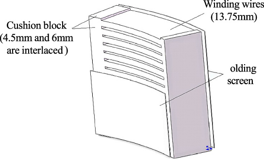
The single 13.75 mm high winding.
According to the pressure difference Δp at the inlet and outlet of the model by the flow field calculated and the corresponding flow Q, the fluid resistance under this flow can be obtained according to formula (1) [20].
The unit of fluid resistance h is Pa, and its relationship with flow rate Q can be considered as shown in Eq. (2)
The high-voltage, medium-voltage, low-voltage and voltage regulating windings in the winding oil circuit are connected in parallel, as shown in formula (3).
In the transformer with strong oil circulation guidance, In the transformer with strong oil circulation guide, the oil circuit circulation is driven by oil pump. The faster the oil flow velocity driven by the oil pump is, the lower the head is. The flow resistance curve in the winding area will intersect the head curve of the oil pump at one point, which is the working point of the oil pump. Therefore, as long as the working point of the oil pump is determined, the internal oil speed of the transformer is also determined. In this paper, only the flow of high-voltage winding is calculated in the fluid field, the flow of medium voltage winding and low-voltage winding can be obtained by Eq. (3). Then the average flow rate calculated in the fluid field is substituted into the thermal network for field circuit coupling.
Basic assumptions
When the temperature of oil immersed transformer is calculated by the thermal network method, there is no need to model the whole transformer because of the symmetrical structure of the three-phase transformer.
In order to simplify the calculation and consider the repeatability of oil immersed transformer structure, only the middle phase is taken for modeling analysis. The model includes core, yoke, shroud, oil channel, low-voltage winding, medium voltage winding, high-voltage winding and box wall, and the following assumptions are made: The three-phase heat dissipation and cooling conditions of the oil immersed transformer are the same, only one phase of the main column is taken for calculation; The loss of pulling plate, clamp and other structural parts is very small, which have little influence on the temperature, it is not considered in this paper; As the folding screen in the prototype is cardboard, it is not completely insulated, so it should be considered in the calculation; The change of thermal conductivity of each component of oil immersed transformer with temperature is ignored; The influence of gravity on the fluid flow characteristics of transformer is ignored.
The parameters of thermal network model
The equivalent thermal resistance
In the thermal network model of oil immersed power transformer, the heat of the transformer is transferred through the equivalent thermal resistance, and finally reaches the heat balance state. In this paper, two equivalent thermal resistances are considered in the thermal network model.
1. Thermal-conduction resistance
When there is a temperature difference between the internal parts of the oil immersed transformer, the heat will be transferred in the transformer by means of heat conduction. The heat conduction resistance of the heat network model in this paper can be divided into axial conduction and circumferential conduction. The heat conduction resistance can be calculated by the following formula [21]
The thermal conductivity of transformer parts
2. Thermal-convection resistance
When the solid surface contact with fluid directly, the contact surface will produce heat exchange because of the different temperature, the thermal-convection resistance can be calculated from [22].
If the Nusselt number is known, the convective heat transfer coefficient of each part of the transformer can be calculated. For the calculation formula of the Nusselt number of heat dissipation on the winding area of the strong oil circulating transformer can be referenced [23].
Compared with other fluid parameters, the dynamic viscosity coefficient of oil immersed transformer is greatly affected by temperature. The dynamic viscosity coefficient of transformer oil is affected by temperature as shown in Fig. 4.

The dynamic viscoity coefficient of transformer oil varies with temperature.
It can be seen from Fig. 4 that the dynamic viscosity coefficient of transformer oil changes greatly with temperature, which must be considered in calculation. Through repeated tests of viscosity coefficient of transformer oil and data fitting, the real-time viscosity coefficient of oil can be obtained from
The formula (6) directly provides the basis for the coupling of fluid characteristics and heat transfer characteristics of transformer. The real-time convective coefficient of transformer fluid can be obtained by using formula (4) ∼(6) iteration repeatedly, which is helpful to improve the accuracy of thermal network method in calculating the temperature of oil immersed power transformer.
The loss of transformer during operation will be converted into the heat of transformer, which will change the heat transfer system of transformer. Before reaching the steady state, the relevant electromagnetic parameters in the transformer will change with the change of temperature. Therefore, the heat capacity must be added to the model to dynamically reflect the temperature change inside the transformer. The calculation of heat capacity is shown in Eq. (7).
And specific heat capacity of oil immersed transformer each component is shown in Table 4 [19].
The specific heat capacity of transformer parts
When solving the thermal network model of transformer, each node needs to meet the thermodynamics law and energy conservation principle [24,25].
The energy conservation equation of each node in the transformer thermal network model can be expressed as follows:
It can be seen (9) that the thermal conductivity matrix is a n × n symmetric matrix, which provides great convenience for calculation. If the Eq. (9) of energy conservation of each node of transformer thermal network model is rewritten into matrix form, it can be expressed as follows:
It is worth noting that since this paper does not consider the change of transformer performance during transformer starting, the introduction of heat capacity matrix in this paper is not to calculate the change of transient temperature rise of submersible motor, but to change the time variable into iteration times through the introduction of heat capacity and consider the influence of temperature on the parameters of formula (1), Gauss Seidel method is used to couple the temperature electromagnetic fluid flow characteristics of transformer, so as to make the model closer to the actual operation of transformer and achieve the purpose of accurate calculation of transformer winding temperature.
When establishing the thermal network model of oil immersed transformer, the structure of transformer, the boundary of each part connection and the characteristics of heat transfer should be considered. In order to simplify the calculation, this paper only takes one phase and establishes the thermal network model of transformer. Considering the calculation accuracy and reducing the calculation workload, the nodes of transformer thermal network model are reasonably divided, which contains 90 nodes, as shown in Fig. 5.
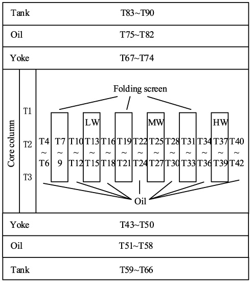
The temperature node of oil immersed power transformer.
It can be seen from Fig. 5, T1–T3 are temperature nodes of iron core, T4–T6 are temperature nodes of transformer oil, T7–T9 are temperature nodes of folding screen, T10–T12 are temperature nodes of transformer oil, T13–T15 are temperature nodes of low-voltage winding, T16–T24 are temperature nodes of oil, T25–T27 are temperature nodes of medium-voltage winding, T28–T30 are temperature nodes of oil, T31–33 is the temperature node of folding screen, T34–T36 is the temperature node of oil, T37–T39 is the temperature node of high-voltage winding, T40–T42 is the temperature node of oil, T43–T50 is the temperature node of lower yoke, T67–T74 is the temperature node of upper yoke, T51–T58 is the temperature node of oil, T75–T82 is the temperature node of oil, T59–T66 is the temperature node of lower tank wall, T83–T90 is the temperature node of upper tank wall. The thermal resistance between the temperature nodes N and M is defined as R n−m , because of the space limitation of the network model figure, this paper does not mark it in the network model figure.
The thermal network model of oil immersed power transformer is shown in Fig. 6. Three temperature nodes are set up along the axial direction for iron core, vertical oil channel, folding screen and low, medium and high voltage winding, which is the top, middle and bottom nodes to reflect the average temperature of each part. The thermal network model includes core, yoke, folding screen, oil channel, low, medium and high voltage winding and box wall.

The model of single-phase thermal network in oil immersed power transformer.
The calculation results of flow field
Figure 7 shows the flow field distribution in the end winding section when the inlet velocity is 0.35 m/s.

Flow field in 1/16 of ending HV winding.
It can be seen from the Fig. 7, due to the function of the oil baffle, the cooling oil flows in from the inside and out from the outside of the winding oil circuit. At the inlet and outlet, the velocity is high, and the average velocity is 0.5 m/s. At the same time, it can be clearly seen that there is a gap flow between the winding coils, and the flow velocity between the lower winding coils is higher, the average flow velocity is 0.2 m/s. the flow between the gaps becomes slow from the bottom to the middle, the average velocity is 0.08 m/s. At the upper end, the velocity between the gaps gradually increased to 0.3 m/s.
The winding section in Fig. 8 is the middle two sections of the winding oil circuit. In this calculation, the inlet is the outside of the winding oil circuit, and the outlet is the inside of the oil circuit. The flow velocity at the inlet and outlet is also high, which is 0.45 m/s. The oil flow state in the Fig. 8 is similar to that in Fig. 7, and there is obvious gap flow, but the gap flow rate is slightly lower than that in Fig. 7 due to the wide space between the winding coils.
Flow field in 1/16 of middle HV winding.
In this paper, four 4b2.80-4.5/2.2v, yf-315 oil pumps are used, and the flow velocity of internal working point of single oil pump is shown in Fig. 9, the velocity of the working point of a single oil pump is 31.2 kg/s.
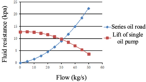
The Solving of operating point in one pump.
The percentage of winding flow to total flow is as follows:
The distribution of oil flow in winding
The winding velocity is determined, it can be substituted into the later thermal network model to calculate the field circuit coupling and obtain the average temperature distribution of each point.
Heat source analysis
The heating of transformer is mainly caused by loss. The loss of transformer is mainly composed of no-load loss and load loss. The no-load loss includes hysteresis loss, eddy current loss and additional core loss. Load loss includes DC loss, eddy current loss and unbalanced current loss in parallel conductor. Since the additional core loss and unbalanced current loss are very small, they are ignored in this paper [26].
The loss of the prototype is shown in Table 6.
The loss of each part of the transformer
The loss of each part of the transformer
In this paper, considering the highest temperature rise of transformer, the temperature of oil set as 70°C, and the inlet velocity of winding oil circuit is 0.35 m/s. The temperature of oil immersed transformer is calculated based on the thermal network method. According to the first law of thermodynamics, the temperature of each node of the thermal network model of oil immersed transformer is calculated iteratively. The iterative process of the temperature of each node of the thermal network model of transformer is shown in Fig. 10.

The iterative calculations of thermal network model.
It can be seen from Fig. 10 that the iterative calculation converges in 2800 steps, and the temperature of each node tends to be stable and no longer increases.
The calculation results of thermal network model of oil immersed transformer are shown in Fig. 11.

The oil-immersed transformer temperature calculation results based on thermal network method.
In the Fig. 11, the hottest spot is at the high-voltage winding, the temperature is 77.97°C, the set ambient temperature is 20°C, and the temperature rise relative to the air is 57.97K. It shows that the winding temperature rise is within the class a insulation limit of transformer, which can ensure the stable operation of oil immersed transformer. It can be seen from Fig. 11 that the main heat dissipation direction of the oil immersed transformer is the circumferential direction, the transformer oil in the oil tank takes a lot of heat, while the axial direction of the oil immersed transformer only plays an auxiliary heat dissipation effect. Due to the repeatability of oil immersed transformer structure, the heat dissipation form of each phase is basically the same. The temperature distribution of other phase can be obtained by changing the relevant thermal parameters by changing the corresponding boundary conditions in Fig. 6.
Comparison between the calculation results of the temperature field and the thermal network method
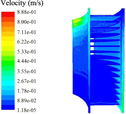
The hot spot temperature of oil immersed power transformer is generally located on the high-voltage winding, so this paper only solves the temperature field of the high-voltage winding to calculate its temperature distribution, and the results are shown in Fig. 12.
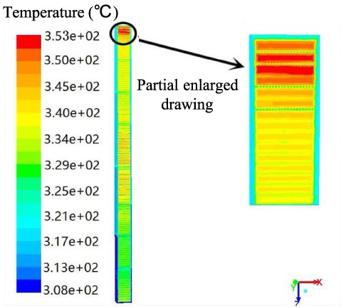
The high-voltage winding temperature distribution.
It can be seen from Fig. 12 that the change trend of the axial temperature of the high-voltage winding is the lowest at the oil flow inlet, which is 51.85 °C, and the temperature rise is 31.85 K. The temperature in the middle part of the winding is 76.85 °C and the temperature rise is 56.85 K. Because of the poor heat dissipation condition, the temperature of the upper part of the middle part decreased slightly, which is 66.85 °C and the temperature rise is 46.85 K. Finally, it reaches the hottest spot at the second wire cake at the bottom of the top, the temperature is 79.95 °C, and the temperature rise is 59.95 K.
The temperature field of high-voltage winding is compared with the calculation result of thermal network method, as shown in Table 7.
Comparison of temperature rise results calculated by finite element method and thermal network method for high voltage winding
It can be seen from Table 7 that the difference between the calculation results of temperature field and thermal network method is about 3 °C, and the relative error is 3%.
In comparison, the finite element method uses commercial software, which can comprehensively calculate the transformer temperature, accurately find the hot spot temperature and facilitate post-processing. However, the finite element method has high requirements for computer hardware, poor adaptability to complex models and long calculation time. The thermal network method is formed by following the physical heat transfer law and comparing the Kirchhoff voltage law and Kirchhoff voltage law on the electrical network. The thermal network method has low requirements for computer hardware and is convenient for engineers to master. However, the solution of model parameters in thermal network method will directly affect the accuracy of motor temperature rise calculation, and the specific location of thermoelectric temperature cannot be determined, which needs to be obtained by ensemble finite element method.
In order to verify the accuracy of the calculation method, the prototype is tested. The winding temperature is measured by optical fiber. The optical fiber probe at the cushion block at the lower side of 5, 50 and 100 cakes of HV, MV and LV winding is installed to measure the temperature outside the insulation of the wire cake. The optical fiber probe is embedded in the winding coil. In order to eliminate the measurement result error caused by the flow of a single oil circuit, the optical fiber probe is evenly arranged in the peripheral direction of the winding [28]. The installation of optical fiber sensor is shown in Fig. 13.

The installation of optical fiber sensors.
According to the national standard gb1094.1-1996, when the temperature change of the top oil is less than 1 K/h under the condition of rated operation, and lasts for 3 hours, the temperature rise can be considered stable. The average value of the last hour’s experimental data is taken as the experiment result. Now, the experiment results are compared with the calculation results of thermal network method, and the results are shown in Table 8.
The comparison between experimental value of windings and thermal network method
It can be seen from Table 8 that the temperature measured in the test is 2–3 °C lower than that calculated by the thermal network method, which the result is within the range of 5°C of the standard value and can be regarded as qualified. The error is because the probe is placed in the lower pad of the winding, its temperature is slightly lower than the average temperature of the winding cake. Therefore, it can be considered that the deviation between the actual winding temperature and the temperature calculated by this method is small, and the calculation accuracy meets the needs of design and verification. The maximum relative error of field calculation is 5.6% because only local calculation does not reflect the influence of each part, while the thermal network method considers the interaction of each part, so it is closer to the experiment value.
According to the actual operation and special structure of the oil immersed power transformer, based on the field-circuit calculation, the average temperature and temperature rise in the whole area of the oil immersed power transformer are obtained in this paper, the following conclusions can be obtained: In the analysis and calculation of winding fluid field, only the typical winding structure is modeled and calculated. Taking the high-voltage winding as an example, the three-dimensional temperature field model can be reduced by 3∕4. The repeatability of the axial oil circuit is fully considered, other winding sections are solved by the fluid field under the action of oil flow. The average flow velocity of the fluid is substituted into the thermal network, and the temperature distribution of the transformer is calculated by the field-circuit coupled. The heat capacity is introduced to the thermal network model to change the time variable into the number of iterations, and the average temperature of each point can be displayed dynamically after the iteration. When calculating the equivalent thermal resistance, the influence of temperature on the viscosity coefficient of transformer oil is considered. Taking the high voltage winding as an example, compared with the calculated results of temperature field and thermal network method, the results show that the thermal network method is closer to the test data, and the maximum relative error is only 3.2%.
Footnotes
Acknowledgements
The paper was supported by National Natural Science Foundation of China. (Grant No. 52077047) and the Natural Science Foundation of Heilongjiang Province, China (Grant No. LH2020E092).