
Abstract
This research introduces a magnetorheological elastomer (MRE) bushing that has the potential to be applied to vibration control for automotive applications. An annular shape of MRE bushing is designed and fabricated by natural rubber (NR) based MRE with homogenous distribution of carbonyl iron particles (CIPs). The component consists of five parts, which are the inner and outer pipes, MRE, coil bobbin that wound by an electromagnetic coil, top and bottom ring plates, and housing. Based on a conceptual design, the electromagnetic circuit is simulated using Finite Element Method Magnetics (FEMM) software for analyzing the distribution of magnetic flux. The fabricated MRE bushing is undergone a compression test and load adhesion test for the performance evaluation. The compression test is conducted by using the Universal Testing Machine (UTM) under various applied currents to obtain the force-displacement and stiffness behavior of the device. This study demonstrated that higher forces and stiffness are achieved compared to other MRE bushings. From here, at 5.5 mm of displacement, the ranges of forces are from 7.1 kN (off-state) to 8.5 kN (on-state at 2.5 A). Furthermore, the stiffness is increased by 19% from off-state to 2.5 A. Overall, the fabricated MRE bushing shows a significant response with the presence of the magnetic field from the simulation studies and experimental results. Thus, it has the potential for vibration control due to the ability to control rigidity.
Introduction
Suspension bushing is a component that has been used in a suspension system of automotive vehicles to reduce vibration and noise, and which can also act as an isolator by decreasing the external loadings and transmitting the vibrations between parts. Even though the suspension bushing is a common component in automobiles, it is still challenging to foresee the actual behavior because of its dynamic characteristics [1–6]. In general, natural rubber (NR) is mainly used for the elastic body of the suspension bushing and other automotive devices and components due to its high mechanical properties. However, to obtain a variable, controllable and tunable stiffness of a component, researchers begin to investigate the use of magnetorheological elastomer (MRE) as a compound in the vibration absorption devices. In general, the rheological properties of MRE can be changed rapidly and reversibly by controlling the input of the magnetic field [7]. For that reason, suspension bushing made from MRE, which is also known as MRE bushing, was introduced to overcome the passive conventional bushing to control a broad range of excitation frequencies and strain amplitudes [8–10]. Thus, by utilizing MRE, the stiffness of the bushing can be controlled and tuned by using an electromagnetic circuit, where the input current will vary the magnetic field applied to the bushing and thus, controlling the stiffness of the bushing swiftly.
Several approaches had been proposed to use MRE for resolving the limitation of conventional suspension bushing. MRE bushing designed by Kumbhar et al. [11] was fabricated by using silicone rubber-based MRE and compared with conventional bushing in terms of their transmissibility related to isolation. The typical transmissibility curve in Fig. 1 showed that as frequency increased, the amount of energy transmitted from vibrations reduced, which indicated the isolation performance of the MRE bushing increased. Besides silicone rubber-based MRE, there are other previous studies that were using NR based-MRE (NR-MRE) compound for their bushing. A prototype of MRE bushing had been patented by Elie et al. [12] and the result showed an increment of stiffness from off-state (without the presence of magnetic field) to on-state (with the presence of magnetic field). The maximum force that acted to the MRE bushing was varied from 150 N (off-state) to 200 N (on-state) for radial and 225 N (off-state) to 350 N (on-state) for axial, with the stiffness ranging between 450 to 700 N/mm for axial and 600 to 850 N/mm for radial. Thus, it indicated variable values of forces and stiffnesses that could be obtained by varying the input current. In particular, it was shown that the MRE bushing demonstrated a flexible loading capacity with the magnetic field, which cannot be achieved by a conventional bushing. Apart from that, Abdelfatah et al. [13] had varied the stiffness of MRE bushing in a motor vehicle using a variable magnetic field. The variable MRE stiffness values were obtained to provide variable stiffness to the bushing. Indirectly, it improved the stability and handling of a vehicle compared to the conventional passive bushing. Thus, to optimize the performance of stiffness and damping, Ginder et al. [8,9] presented stress-strain loops obtained from testing done on an MRE bushing. The experimental result showed that, as the current increases, the slope and the area of the loops increased, which indicated an increment to the stiffness and damping of the bushing. They found the maximum forces and effective stiffnesses were ranging from 222 N (off-state) to 238 N (on-state), 400 N/mm (off-state) to 500 N/mm (on-state) for axial and 600 N/mm (off-state) to 800 N/mm (on-state) for radial, respectively. Therefore, it can be said that the stiffness of the MRE bushing has increased dramatically during the on-state and linearly with the applied current. Consequently, this semi-active MRE bushing is feasible to effectively isolate vibration and noise by controlling the magnetic fields from manipulating the applied current in the electromagnetic circuit. In particular, high stiffness produced stiffer behavior, higher resistance to elastic deformation, and higher yield strength [14]. Due to that, high stiffness could support a higher load. Apart from that, low stiffness behavior tended to be soft or porous in a real application. Hence, MRE bushing could achieve a wider range of forces and stiffnesses to enhance high performances.

Typical transmissibility curve [11].
On the other hand, in terms of the MRE bushing model, Blom et al. [15] investigated and predicted an MRE bushing based on an engineering stiffness formula model. A dynamic torsional stiffness model was studied for the magneto-sensitive rubber bushing for the influences of frequency, amplitude and magnetic fields. However, it was only based on the mathematical modelling, which showed a 40% increment of stiffness when induced by the highest magnetic field. Since several studies had shown the opportunity and prospective of the proposed MRE bushing, further developments were carried out on the analysis of the electromagnetic circuit design in simulation studies and MRE material, which are crucial for the enhancement in the product development. Kim et al. [10] conducted a simulation study to enhance the design and shape of MRE bushing. Finite element analysis, magnetic field analysis, and magnetic circuit design were utilized to optimize features of MRE bushing design, and thus, improved the performance of MRE bushing. However, it is not managed to be fabricated for experimental or real world use.
Apart from the magnetic field analysis, material selection is vital for the performance of MRE bushing. Even though silicone rubber based-MRE was one of the materials [16,17], Chen et al. [18] showed that the NR-MRE improved the tensile strength by almost ten times compared to silicone rubber-based MRE. In fact, NR provides better practicability and had been used for numerous mechanical system devices, especially in vibration control [19–22]. Thus, the utilization of NR as a matrix with carbonyl iron particles (CIPs) as a filler to form NR-MRE, could improve its mechanical performance [18,23,24]. Furthermore, the performance of MRE could be enhanced by increasing the content of CIPs up to 70% [25,26]. However, there was a concern about the brittleness of the material once it exceeded some values depending on the type of matrix [27–29]. As a prior work that used MRE compound in their device, Wahab et al. [22] utilized 60 weight percentage (wt%) of CIPs to their MRE-based isolator. This amount of CIPs (60 wt%) enhanced the magnetic flux distribution in the device. Therefore, a suitable amount of wt% of CIPs should be considered before utilizing the MRE into devices.
Meanwhile, conventional bushing had achieved higher force and stiffness which are above 3000 N and 1000 N/mm, respectively [1]. These high force and stiffness have not been achieved yet by MRE bushing. Previous MRE bushings had obtained a low range of forces between 150 to 350 N and effective stiffnesses between 400 to 850 N/mm [8,9,12]. An MRE compound, whose stiffness can be manipulated by the magnetic field, can overcome this behavior from the conventional bushing. Hence, a great opportunity can be achieved from high forces and stiffness by applying the MRE compound to the bushing.
For the MRE bushing used in this study, the rubber compound used is NR-MRE which differs from MRE bushing done by Kumbar et al. [11]. Apart from that, the CIP content in the MRE compound is 60 wt% which is higher than prior works related to MRE bushing [8,9,11,12,15]. In addition, the coil is positioned externally for this MRE bushing which differs from prior works as well [8,9,12]. Therefore, this study aims to overcome the limitation in producing higher force and effective stiffness from MRE bushing. It is designed using NR-MRE compound and materials that would allow highest magnetic flux to flow into the MRE bushing. Then, the MRE bushing was tested under compression loading to examine the performance that provides adjustable stiffness by varying the magnetic field intensity at various applied currents.
The structure of this paper is by sections and this is the introduction section (Section 1). In Section 2, the design and magnetic field analysis using Finite Element Method Magnetics (FEMM) simulation are presented. Section 3 describes the fabrication of the MRE bushing which involved few steps. Furthermore, Section 4 shows the experimental description for this finding. Meanwhile, Section 5 presents result and discussion for force and stiffness behavior. Finally, conclusion of the study is drawn in Section 6.
Electromagnetic circuit design is a crucial element to be studied in designing the MRE bushing. FEMM is a software for simulating and evaluating the configuration of the electromagnetic circuit design for MRE bushing. In this software, several parts of MRE bushing has been drawn, and each part has been assigned based on the material properties. Proper characterization of magnetic or non-magnetic materials for each part would have a great effect on the distribution of the magnetic flux density in the device.
All parameters for MRE bushing such as geometrical dimensions based on the conceptual design and type of materials were assigned in FEMM. The model of MRE bushing was created in two-dimensional (2D) cross-section design and axisymmetric based on the built-in features of the software. For the design of MRE bushing, the cross-section drawing is shown in Fig. 2(a). The structural parameters of the MRE bushing are presented in Table 1. In addition, the weight of the bushing is 560 g. The drawing of the 2D axisymmetric MRE bushing with simulated magnetic flux density distribution is shown in Fig. 2(b). The structural design of the MRE bushing was based on prior works which is suitable for industrial and research scales [1,8,9,11,12]. Generally, the structural design of the MRE bushing had been enhanced so that the ultimate aims can be achieved.
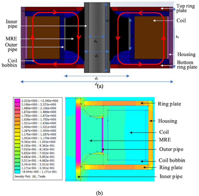
(a) Schematic cross section of MRE bushing and (b) 2D axisymmetric simulated magnetic flux density with input current of 2.5 A.
Structure parameter of the MRE bushing
The MRE bushing model was divided into five parts. The first part is the top and bottom ring plates, while the second part is the MRE. The third part is the inner and outer pipes, whereas the fourth part is the electromagnetic coils and coil bobbin. Finally, the fifth part is the housing. The first, third and fifth parts were made of magnetic material, AISI 1020. The material was chosen due to the balance of high hardness and magnetic permeability compared to other materials. For the housing, it was used as a cover and to guide the magnetic flux to pass through the effective area of MRE. It was fixed and attached to the top and bottom ring plates. Meanwhile, the second part was referred to the MRE with 60 wt% CIPs that was sandwiched between the inner and outer pipes. The magnetic permeability of the MRE was based on the VSM test data that measured the magnetic characteristics. The obtained B-H curve for the MRE with 60 wt% CIPs was in line with Wahab et al. [22], in which the magnetic flux density of the MRE material had a linear relationship with the magnetic field intensity. The MRE was fabricated by compounding the NR matrix, additives and 60 wt% content of CIPs, same as the one used in Wahab et al. [22] to achieve a better magnetorheological (MR) effect in the bushing. Meanwhile, the CIPs used was type C3518 purchased from Sigma-Aldrich Pty. LTD with density of 7.86 g/cm3, and average diameter of 6 μm.
Then, the fourth part was referred to the electromagnetic coils using copper wire SWG 24 that wound around a coil bobbin. The coil bobbin was made of non-magnetic material, which was aluminum type 6061-T6. By using an ohm meter, the total electric resistance of coil was 81 Ω. SWG 24 was chosen based on the thickness of the wire and the maximum current input allowed, where it would produce the highest intensity of magnetic field, H from Eq. (1) [30] as follows:
Description of each part and materials
Once the material selection and parts have been confirmed, then, the FEMM simulation was run. In terms of the meshing in the simulation, the FEMM created a mesh with 7810 nodes, with a fine triangular mesh at the important region of the inside of the magnetic core and a coarse triangular mesh at the outside region. In the simulation, the current was varied from 0.5 to 2.5 A. The observed MRE area is shown in Fig. 3 in which the magnetic flux passed through the bottom and top ring plates, inner and outer pipe, housing, and MRE structure in the bushing. The magnetic flux density was measured in three different effective regions, namely A, B, and C, based on the area observed. Region A was located at the longest area of MRE, near to inner pipe, whereas the Region B was positioned in the middle of the MRE, while for Region C, it was placed near to outer pipe. It was measured from top to bottom in the cross section of the MRE bushing.

Magnetic flux distribution in the MRE bushing.
Magnetic flux distribution from simulation study at the effective regions of MRE is observed to study the effect of changing the input current. Figure 4 shows the magnetic flux density concerning the effective regions of MRE under the various input currents. Each part of the MRE bushing, assigned by the respective material was significant in ensuring achievable optimum magnetic flux in the MRE area. The increment of the average magnetic flux density when increasing applied current from 0.5 to 2.5 A for Regions A, B and C was from 0.08 to 0.26 T, 0.02 to 0.21 T, and 0.01 to 0.25 T, respectively. It can be concluded that as the applied current increases, the magnetic flux density increases. The increment of the average magnetic flux density and induced magnetic force for Region C was the highest because the area was located at the nearest to the electromagnetic coil compared to others. This is due to the concentration of magnetizing force that was higher at the location near it. Meanwhile, Region A has the lowest average magnetic flux density due to two factors, the longest area of MRE, and the most far location from generated magnetic field strength. Magnetic flux leakage was more prevalent at the longer area of MRE that contributed to the lower average of magnetic flux density.
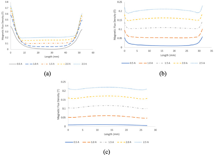
Magnetic flux density under the various input currents penetrated through MRE for (a) Region A, (b) Region B and (c) Region C.
Based on the previous works, the stiffness of the MRE can be increased when the magnetic field is being enhanced [22,32]. This holds true later in the next section when the stiffness is measured from the experimental testing. In a nutshell, the higher magnetic flux density obtained can enhance the stiffness of MRE in the bushing.
The structural design of MRE bushing was fabricated based on the analysis of the simulation studies in FEMM. It was divided into two parts, the first was the fabrication of MRE compounds, then continued with the assembly process to produce the device which involved injection molding and machining processes. By incorporating the top and bottom ring plates and housing, the concept of the conventional rubber bushing was altered. Since the top and bottom ring plates and housing were made from the magnetic material, the magnetic flux could be directed to pass through the MRE and formed a closed loop. Besides, the presence of those parts acted as a guidance for the magnetic flux to penetrate through the MRE.
Composition of MRE compound
Composition of MRE compound
∗Phr – Part per hundred rubber.
The fabrication of the MRE compound involved the mixing and curing processes [33]. The MRE compound consisted of NR, CIPs and additives, which was prepared using a two-roll mill machine. Table 3 shows the composition of MRE. Before the MRE compound was being cured, the injection molding process was performed. The process of injection molding started with material preparation, where the uncured MRE was prepared in the shape of strips approximately the size of 1.25 ′′ width and 0.375 ′′ thickness in solid-state. Then, the strips were fed into a rotating screw, which filled a barrel with an appropriate amount of rubber material. Next, a predetermined amount of MRE was fed into the injection unit. The MRE was heated inside the injection chamber until the temperature reached 150 °C before being forced to flow into the cavity of the mold. Based on the thermal resistance, thermal decomposition temperature were ranging from 250 to 276 °C [34]. At this state, the MRE becoming a semi-solid, where the viscosity was relatively low, hence allowing it to fill the cavity. Prior to the injection process, the inner and outer pipe parts were placed inside a bushing mold as shown in Fig. 5(a). This process involved rubber-to-metal bonding assembly, in which the MRE was sandwiched between inner and outer pipes. The MRE was heated and injected under a high temperature and pressure from the chamber to the mold. Hence, the MRE was cured in the mold. Finally, the fabricated bushing was removed from the cavity at the end of the cycle, and the next cycle begins. Figure 5(b) shows the MR bushing after being removed from the mold.

(a) Inner and outer pipes as inserts in the mold and (b) MRE bushing products.
For other parts such as coil bobbin, top and bottom ring plates, and housing, all of them have undergone a machining process. Machining is a process of cutting a piece of raw material into the required final form and size using a manageable material removal process [35]. The top and bottom ring plates have three threaded holes for the bolts locking holder to be attached to the coil bobbin and the housing. Figure 6 shows these parts as configured in the MRE bushing.
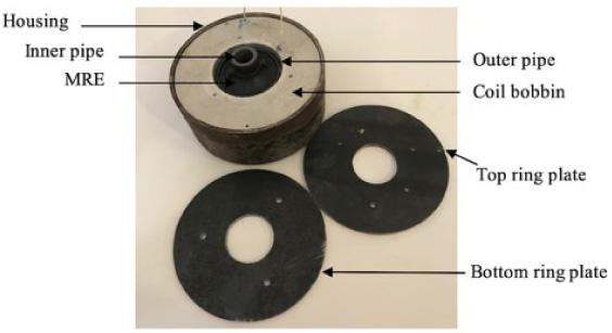
The parts of the MRE bushing.
Once the bushing had been fabricated, it was undergone a compression test which is a non-destructive test. The MRE bushing was investigated to examine the induced actuating force due to the applied current, where the force-displacement behavior was observed. The maximum force of the MRE bushing was evaluated by a series of compression tests by varying the input current. This experiment was performed using a Universal Testing Machine (UTM) manufactured by QC Tech from Taiwan equipped with a 50-kN load cell. The test was performed in two phases under the compression behavior. The first phase was the off-state condition with 0 A, and the second phase was the on-state condition, with the presence of magnetic fields by supplying input currents from 0.5 to 2.5 A with an interval of 0.5 A. The experimental setup for compression test is shown in Fig. 7. In the experimental setup, a jig was designed to hold the MRE bushing. The jig was made up of aluminum so that the magnetic field produced by the coil was not affected by the jig. Hence, it prevented the magnetic field distortion happened. To join with the bottom brackets, a shaft was inserted into the inner pipe of MRE bushing where the bottom brackets were mounted to the testing machine. The 50-kN load cell was installed on top of the jig to measure the load applied to the MRE bushing. The wire coil from MRE bushing was connected to the voltage regulator to provide the input current. The capacity of the voltage regulator is 5760 watt (240 V × 24 A) to supply the magnetic field needed for the experiment. To monitor the temperature of the MRE bushing during the testing, a high-quality thermal imaging camera (FLIR i7) was used. It uses thermal infrared to capture the temperature of the device to ensure accurate temperature measurement on the MRE bushing during testing. The experiment started with the first phase, where the compressive force was exerted to the MRE bushing. When the applied force has been attained, the compressive force from the testing machine on the MRE bushing was released. The same sample had been used for the next phase, which the experiment was continued by increasing the input current up to 2.5 A.

Experimental setup for compression test.
For the next experiment, the bushing was undergone a load adhesion test. This destructive test indicates the maximum tension force required for separating two adhered parts along with the interface. The test is to measure the adhesive strength between the metal and rubber. Since the MRE was sandwiched between inner and outer pipes, the adhesive bonded the rubber and metal together. Figure 8 shows the experimental setup for load adhesion test. It was consisted of six main components, which are load cell, testing machine, upper bracket, jig, safety cage, and reading panel. A load cell is installed on top of the rig to measure the load applied to the bushing. The bottom part of the bushing was clamped inside the fixed jig and the jig was functioned to hold the bushing in a fixed state with no movement at all. Meanwhile, the upper bracket was clamped to the inner pipe part. Since this experiment was a destructive test, the safety cage was used as a cover to the bushing and other components for ensuring safety during experiment. The bushing was placed inside the safety cage, where the experiment only could be started when the safety cage was locked. In this experiment, the force direction was vertical in line with the tension direction. As the experiment started, the upper bracket pulled up the inner pipe to the vertical direction so that the parts could be separated. The reading panel showed the maximum force measured from the load cell.
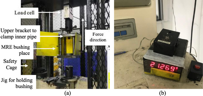
Experimental setup for load adhesion test (a) test rig equipped with load cell. (b) Reading panel.
Compression test
The result of force versus displacement is shown in Fig. 9. In this test, as the displacement increases, the force increases as well. The same trend was obtained at all other applied currents. Higher displacement requires higher force exerted on the bushing. As the machine pressed the bushing, the compression displacement increased. This means that greater forces are required to compress the bushing further.

Force and compression displacement at different applied currents.
Initially, the forces for each applied current were having the same trend, where the forces increased as the displacement increased. In particular, it showed that the forces acted on the MRE bushing demonstrating a linear relationship with the applied currents. The region from 0 to 3.5 mm as observed in Fig. 9 is a linear area which is in line with Wahab et al. [22]. The increment of the forces in this range was up to 4500 N. Subsequently, at 4 mm of compression displacement, the forces were further increased but with divergences between each applied current. The maximum force was recorded for the highest current of 2.5 A, with 8.5 kN at 5.5 mm of compression displacement. The trends were declined by lowering the applied current, where at 5.5 mm of displacement and 2.0, 1.5, 1.0, 0.5, and 0 A, the forces were 8.3, 7.9, 7.6, 7.4, and 7.1 kN, respectively. At off-state condition, the percentage increment of force at displacement from 4 to 5.5 mm was 52%. Meanwhile, at on-state condition, the percentage increment at 0.5, 1.0, 1.5, 2.0, and 2.5 A were 56, 60, 68, and 75%, respectively.
This finding revealed that the presence of magnetic field was strongly influencing the behavior of MRE. In this investigation, the compression forces increased as the magnetic field strength increased by raising the applied current. To relate this finding in terms of interparticle reaction of MRE, the magnetic particles embedded in this MRE bushing were well dispersed and varied in size. Apparently, the isotropic arrangement of magnetic particles inside the rubber matrix was randomly distributed because of the effect of Brownian motion that allows the particles to arrange themselves in a random distribution during curing [36]. Pertaining to particles arrangement, prior studies by Qiao et al. [37] revealed that isotropic distribution strengthened with the increasing applied currents and also retained the elasticity of the compound. Besides, Gong et al. [38] showed that isotropic MRE has a high potential for generating significant storage modulus improvement when applying magnetic field. These statements were then proven in this work, which showed the compression force increased under the influence of the magnetic field. These clearly exhibited that the embedded magnetic particles were responded toward magnetic fields. To justify this point, during the on-state conditions, there were interactions between the particles due to the presence of magnetic field [39]. As the magnetic field intensity increased, the interparticle reactions were stronger. As mentioned by Miao et al. [40] when the interactions between the particle were stronger, it will subsequently reduce the interparticle distance between them. Therefore, the stronger the interactions between the particles and matrix resulted in less deformation of MRE which referring toward more rigid properties. In this regards, the magnetic field inducing a dipole moment within particles causing them trying to align along the magnetic field direction [26]. Hence, it was leading the bushing behavior to become more rigid with the presence of higher magnetic field intensity, therefore, required a greater force in compression. Thus, stronger magnetic fields showed a significant response to the behavior of MRE bushing. As mentioned by Yang et al. [41], in addition to the resistance of rubber matrix, when a certain current level was applied to the MRE, the iron particles were also held by the magnetic force between the particles, which make the extensibility of the chain structure even less [41]. Thus, it can be clearly observed that the forces of MRE bushing especially at 5.5 mm of displacement are directly proportional to the applied currents.
In this research, disregarding the particle size, the wt% for the magnetic particles of MRE bushing plays an important role that affects the rigidity and elasticity. This MRE bushing was embedded with 60 wt% of CIPs. In general, a higher fraction of magnetic particles decreased the amount of matrix carrier [42]. However, the response of MRE towards the magnetic field seems better with a higher concentration of magnetic particles. Nevertheless, magnetic particles with fraction higher than 70 wt% will lead to brittle behavior and becoming less elastic [27,29]. This showed that 60 wt% of the magnetic particles in this MRE bushing is optimum to generate the elastic response towards magnetic fields. Otherwise, excessive wt% of magnetic particles leads to an insignificant amount of matrix, less matrix dependent, less elasticity, and consequently exhibited brittle failure behavior [42]. Thus, this MRE bushing is ideal with its wt%, subsequently, achieved controllable rigidity as the compression forces increased when the currents increased. Not only that, the bushing with magnetic particles of 60 wt% contributed to higher force characteristics which ranges from 7.1 to 8.5 kN from off-state to on-state. It can be compared with the previous researchers which only obtained lower range of force values of 150–350 N [8,9,12].
Moreover, in terms of displacement control, the forces that acted on this bushing at compression displacement from 0–4 mm (low range of displacement) on each applied current were similar because this range is at the outer layer of bushing. This means the same acted forces were required on that range even in the off-state. However, as the compression displacement increases from 4–5.5 mm (high range of displacement), the acted forces on each applied current are drastically changed. During this condition, the machine compressed the bushing further to measure the compressive force. In this high range of compression displacement, the magnetic field strength is stronger. Furthermore, due to the magnetic saturation, which is higher in this range explains the divergence of forces that happened as the displacement goes further. Thus, the results revealed that it made the MRE bushing to become stiffer when higher current applied. Apart from that, it is known that the stiffer behavior led to the harder deformation of MRE. For this reason, a higher amount of force is needed to compress the MRE bushing further since the elastic body of MRE are harden. In terms of the MR effect, a strong MR effect resulted in a higher strength of the magnetic force [23]. Thus, the applied current at 2.5 A exhibited higher MR effect compared to others. Due to that, the increment of forces is attributed to the increment of rigidity and elasticity effects on the MRE bushing.
In addition, this finding can relate to the MRE bushing performance by analyzing the microstructure behavior of the MRE. The mechanical and viscoelastic properties are prominently dependent on the magnetic flux density applied [36]. For microstructure behavior of MRE, the field-induced shear modulus are increasing with the increment of magnetic flux density applied where the increment of shear modulus comes from the attraction of magnetized particles [36]. The greater the magnetic field, the greater the attraction inside microstructure, and thus, the MRE will be harden which means a greater force is exerted to the bushing. In the microstructure, forces in MRE are expressed using micro stress and strain, and the distribution of stress applied during the test is the most commonly studied parameter for both elastic and plastic deformation of MRE [43]. Therefore, it contributed to the enhancement of the field dependence of the mechanical properties of MRE when subjected to the applied force and magnetic field.
Additionally, this test measured the compressive force for MRE bushing with the influence of applied currents which is acknowledged scientifically as a smart device. This is because a smart device uses smart material that reacted to external stimulus, which in this case is the magnetic field. Besides, high compression force is one of the mechanical characteristics applied to the MRE bushing which is important to accommodate the loads imposed by the vehicle. The MRE bushing should be able to support and sustain higher loads which the device in the suspension system get impacted with road surface irregularities and different applied loads.
In this section, the slope of the graph obtained from the compression test will be used to indicate the stiffness of the MRE bushing for semi-active control. The stiffness of the MRE bushing is related to the value of applied current, where it is stiffer when more input current is applied. The effective stiffness of the bushing is determined by referring to the linear static spring stiffness concept of Hooke’s law which is used in vibration analysis, defined as the force of the spring. The stiffness data is developed from the force and displacement data using a Hooke’s law equation expressed as:
The general stiffness Eq. (3) is used to calculate the effective stiffness of MRE bushing based on the force-displacement graph. Table 4 shows the values of F 2 for each applied current. Meanwhile, the value of F 1, x 2, and x 1 are constant at 0 N, 5.47 mm, and 0 mm respectively. As demonstrated in Fig. 10, the stiffness is increased linearly by increasing the applied current from 0 to 2.5 A. The percentage increase of stiffness from off-state to maximum on-state (2.5 A) is almost 19%. In particular, when applying 0.5 A, the stiffness is 1355.36 N/mm, a 3.28% increase over the stiffness of the off-state, which is 1312.34 N/mm. Moreover, as the applied current rises from 0.5 to 2.5 A, the stiffness increases linearly. The stiffness for input currents at 1.0, 1.5, 2.0, and 2.5 A are 1390.49, 1459.34, 1524.68, and 1561.70 N/mm respectively. As in Table 4, the effective stiffness increases range from 3.28% to 19%. Based on the result obtained, it can be observed that the stiffness of the MRE bushing increased as the input current increased because the magnetic field strength in MRE also increased.
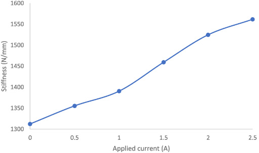
Graph of the effective stiffness versus applied current.
Effective stiffness versus applied current
The result revealed that the MRE bushing achieved controllable, tunable, and adjustable stiffness by manipulating the input current. In general, other than possessing a viscoelastic performance, the stiffness of MRE can be rapidly, continuously, and reversibly controlled by a magnetic field [44]. Based on these results, the stiffness of MRE bushing expressed an appreciable response to the presence of magnetic field. This is due to the interparticle reaction of MRE that occurred when the magnetic field is present, thus affecting the stiffness characteristic [40]. Consequently, it can be observed that the stiffness of MRE bushing is dependable on the magnetic field intensity. Yang et al. [41] had explained the Mullins effect, where when the rubber is stretched to a relative force and then released, the stress-strain curve can be lowered compared to the first stretch. It is inferred that the rubber has been weakened and soften on the next cycle. Hence, due to this Mullins effect, the greatest stress is shown in the first cycle, and the stresses in the following cycles gradually decreased [45,46]. In this MRE bushing, the stiffness increased in the next cycle when increasing the input current due to the presence of magnetic particles embedded that made reaction towards the magnetic field. It clearly remarks the behavior of a smart device where the stiffness can be altered. These trends were similar to the results obtained by other researchers [8,9,12]. In the meantime, the stiffness achieved in this study was in the high values which ranging from 1312–1561 N/mm compared to prior studies of MRE bushing which is lower. Thus, from the analysis done towards the MRE bushing, it is shown that the MRE bushing can contribute higher stiffness during compression loading conditions compared to the previous studies [8,9,12].
Next, the stiffness of MRE bushing in off-state has been compared with the stiffness of conventional bushings. Three conventional bushings named A, B, and C have been fabricated by NR compound with similar rubber shore hardness A (Hs) of the MRE bushing, ranging from 60 to 65 Hs. The stiffnesses of these conventional bushings have been measured by using the same methodology as the MRE bushing. For MRE bushing in off-state condition, the stiffness is 1312.34 N/mm, while for conventional bushings, the stiffnesses ranging from 939.55 N/mm to 1038.45 N/mm. There are about 40% differences between the off-state MRE bushing and conventional bushings. Figure 11 shows the comparison of the stiffness for off-state MRE bushing with the conventional bushings.

Comparison of stiffness for off-state MRE bushing with conventional bushings.
MRE bushing in off-state is stiffer than the other conventional bushings due to the presence of CIPs in the compound. The stiffness of MRE bushing that can be altered and have a wide range of effective stiffness is suitable with the driving condition which requires different applied frequencies on the road during acceleration, deceleration, braking, or cornering. For conventional bushing, the design is based on the compound hardness in which different design requires different hardness due to the fixed behavior [47]. To get the required stiffness, tunable MRE bushing is an alternative for conventional bushing by changing the input current without the need to change different compound. Other than that, the controllable stiffness behavior of MRE bushing contributed to the vibration control of devices. This smart behavior of mechanical devices is attributed to isolating and attenuating excess vibration. Instead, conventional bushing possesses uniform and fixed stiffness behavior, a passive vibration absorption system, and rigid mechanical properties.
In this test, the maximum tension force was obtained at 21.27 kN. It was a destructive test that measured the maximum force required to separate the compound. During the test, the upper grip of the test rig had clamped the inner pipe part and vertically pulled it to produce the tension force. Since the compound of MRE bushing was made from NR, the tension force obtained was higher compared to silicon rubber. It was linked to the high mechanical strength of NR. Besides, the MRE bushing requires high tension force so that the device could maintain its durability even in high force before reaching a certain maximum limit of force. In a real application, the bushing was exposed to a different impact of forces that tended to cause breakage to the rubber. In order to avoid that, the MRE had to achieve a higher tension force to maintain the efficiency and workability of MRE bushing. Figure 12 shows the bushing condition after the test. The outer pipe was still attached with the MRE, which meant the adhesion between the MRE and the outer pipe was good enough that could sustain the high applied force.

The bushing after the load adhesion test.
In this work, MRE bushing was designed, simulated, fabricated, and the acted force was experimentally observed by using a compression test. It had been shown that the utilization of NR-MRE compound with at least 60 wt% of CIPs can provide a high MR effect compared to prior works of MRE bushing which utilizes low wt% of CIPs. However, if more than 60 wt% of CIPs were used, it can lead to brittleness and less elastic behavior. In addition, it will also lead to higher stiffness in the off-state condition. It was also found that the MRE bushing exhibited responses towards different magnetic field, which implies the stiffness tunability of the MRE bushing. From the simulation study, it was observed that the lines of magnetic flux passed through the top ring plate, inner pipe, MRE structure, outer pipe, bottom ring plate, and housing. Therefore, the magnetic flux can be guided to go through the targeted area by manipulating the magnetic and non-magnetic materials of the device. Hence, the MRE can be exposed to more magnetic flux by using this way.
The test for force-displacement of the MRE bushing with different input currents was undertaken in compression loading. The increment in the compressive force produced from the MRE bushing for the compression test is about 52%–75% starting from 4 mm of displacement which the forces start to diverge between each applied current. It had also been shown that when the current 0.5 A was applied from off-state to on-state, the obtained force increased remarkably. As the current raised from 0.5 A to 1 A, the force increased marginally and linearly up to 2.5 A. The same thing can be said about stiffness, where it increase remarkably when the current 0.5 A was applied from off-state, and increase marginally and linearly up to 2.5 A. In addition, the increment in the stiffness can be shown from approximately 3% to 19%. This shows that the stiffness is directly proportional to the applied currents. In addition, the MRE bushing was undergone a load adhesion test in off-state, where the maximum tension force obtained is 21.27 kN. The findings presented in this paper show that the proposed MRE bushing can be used effectively as one of the smart materials in the suspension system. Therefore, by applying the actuating force, higher stiffness can be achieved by tuning the applied current. As a result, based on the size and mass of the system, the stiffness can be controlled by varying the input current of the MRE bushing to anticipate for more generated compression force and suitable for various vibration control applications. In addition, a dynamic test with various frequencies and amplitudes as well as the control system of the proposed device should be taken into consideration and will be addressed in the second phase of this work.
Footnotes
Acknowledgements
This research work is supported and funded by Universiti Teknologi Malaysia (UTM) under UTM Prototype Research Grant (UTMPR) (Vot No. 00L46). The authors also thank Japan International Cooperation Agency Fund (JICA Fund) (Vot No. (4B696). The work is also supported by International Collaboration Grant 2021, Universitas Sebelas Maret.