
Abstract
The application of coaxial magnetic gear (CMG) in wave generator instead of traditional variable speed gearbox can effectively improve torque density and reduce torque ripple. Thus, the operation principle of CMG from the perspective of magnetic field modulation is firstly analyzed in this paper. Then the air gap magnetic fields induced by high-speed and low-speed rotors are studied. And the radial height, inner diameter angle, and outer diameter angle of the modulating pieces (MPs) are optimized by using the combination of response surface method (RSM) and particle swarm optimization (PSO) algorithm to improve the torque transmission capacity of CMG. The CMG is combined with the permanent magnet synchronous machine to get the magnetic-gear permanent magnet synchronous generator (MG-PMSG). The design feasibility of the MG-PMSG is verified from four aspects: static magnetic field analysis, no-load characteristics, load characteristics and load disturbance analysis.
Keywords
Introduction
Wave energy is one of the main forms of ocean energy. Its commercial application is still in the early stages but has a large potential for growth [1]. The energy density of wave energy is higher than those of other renewable energy sources, such as wind energy and solar energy, with longer energy production time and less impact on the environment [2]. Reasonable selection and design of the type and structure of wave power generator is of great significance to the high-efficient and stable power supply of wave energy power generation system [3]. Squirrel-cage induction generator, brushless doubly-fed induction generator, permanent magnet synchronous generator and permanent magnet linear generator are typical types of machines used in wave power generation [4]. However, one of the most significant challenges is the cost reduction of operation and maintenance because most of them need to be combined with gear box [5]. In order to improve the economy of wave power generation and promote its large-scale commercial application, applying magnetic gears (MGs) to wave power generator can achieve easy maintenance and less cost due to their frictionless torque transmission ability [6]. In addition, MGs are simple in structure and easy to be manufactured [7]. It can be combined with traditional generators [8]. This type new combination machine not only has the advantages of traditional electrical machines, such as strong power generation performance and a well-developed control system, but it also has the features of MGs, which transmit speed and torque by MPs [9]. Therefore, it is very suitable for them to be used into wave energy conversion (WEC) system in low speed and direct drive mode [10].
With the development of research on MGs, four new topologies of high-performance MGs appeared at the beginning of this century [11,12]. They are MGs with achievements have greatly improved the utilization ratio, torque density and transmission ratio of permanent magnet.
As shown in Fig. 1(c), one of the most common used structures is the CMG, which could be combined with the permanent magnet synchronous machine. The MPs can change the pole-pairs of magnetic fields, so that all the permanent magnets are involved in the torque transmission, and the utilization rate of permanent magnet could be greatly improved. There have been numerous structural optimizations and performance analyses of CMG. In reference [13], the CMG is mechanically coupled with the traditional permanent magnet synchronous machine in series in the wind power generation system, which reduces the size and weight of the generator, and improves the system efficiency and reliability. In reference [14], the CMG is electromagnetically coupled with the permanent magnet synchronous generator, and a low-speed rotor magnetic gear composite generator is proposed. The magnetic gear is radially combined with the machine to achieve low speed and high torque, which further reduces the generator volume and makes the structure more compact. The working principle, design method, operating characteristics and performance of the external rotor magnetic gear composite machine are described in detail in [15]. The feasibility of its application in the fields of wind power generation and electric vehicle is verified by numerical calculation, finite element simulation analysis and prototype experiment.
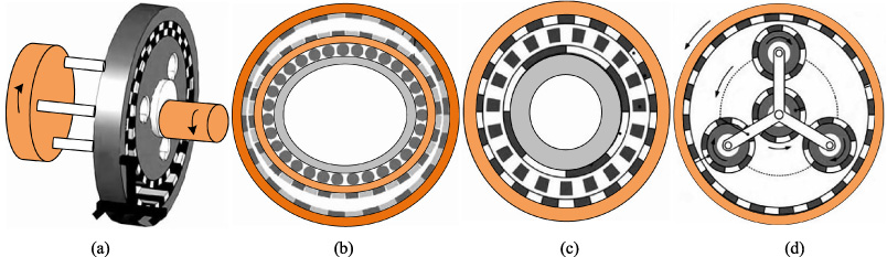
Topological structures of high-performance magnetic gear. (a) MG with few teeth difference; (b) harmonic magnetic gear; (c) MG with magnetic field modulation; (d) planetary magnetic gear.
However, torque density of CMG, one of the most important evaluation criteria for its performance and efficiency, is still at a relatively low level. Therefore, it is of great significance to improve the torque transmitted by the inner and outer rotors. Because of the coupling effect of magnetic modulating ring, the speed and torque could be transferred by effective harmonic generated by inner and outer rotors. Moreover, the output torque of inner rotor and outer rotor are closely related with the effect of magnetic modulating ring. Then, the effect of magnetic modulating ring is closely related with its dimension parameters. Therefore, optimizing the dimension parameters of magnetic modulating ring could effectively increase the torque transmission ability of CMG [16].
In the optimization, when the objective quantity is determined by more than one parameter, optimization strategies that are commonly used are as follow three steps: Obtaining the function expression between the objective function f (x) and the variable to be optimized x through the analytical calculation method. This optimization method is suitable for optimization variables that are easy to be obtained by the objective function. Using the finite element method (FEM). It is used for large-scale modelling and calculation of the optimization object, from which the optimal scheme can be found. However, the number of models needed by this method is very large. When parameters to be optimized are increased to three or more, computer resources and calculation time will be heavily consumed. Using the RSM. First, through the reasonable selection of a series of specific sample points, the finite element test is carried out on them, and the corresponding optimization of the samples are obtained. Then, by fitting finite element calculation results in the function form, the deviation error between the experimental results and the assumed function is minimized. Finally, genetic algorithm, differential mutation algorithm or PSO algorithm could be used to optimize fitted results to achieve the purpose of optimal design.
Therefore, the RSM and PSO are combined to optimize the dimension parameters in this paper. This method can use less sample points to achieve fast optimization speed and better accuracy. And it can effectively improve the transmission torque capability of CMG. Furthermore, a magnetic-gear permanent magnetic synchronous generator is achieved with the optimized CMG. And the rationality of its application in wave power generation is verified by finite element simulation.
The basic structure of CMG is shown in Fig. 2. It is mainly divided into five parts: iron core of low-speed rotor, permanent magnet of low-speed rotor, modulating pieces, permanent magnet of high-speed rotor and iron core of high-speed rotor.

The basic structure of CMG.
The key component of CMG is the modulating pieces, which are arranged by ferromagnetic materials and non-ferromagnetic materials between the high-speed and low-speed rotors. The effective coupling between different pole pairs of permanent magnetic fields on the high-speed and low-speed rotors is realized because of the existence of the MPs [17,18]. Taking the CMG shown in Fig. 2 as an example, this paper qualitatively analyzes the modulation effect of the MPs on the permanent magnetic field of the high-speed and low-speed rotor through the air gap magnetic field distribution.
∙Air gap magnetic field without MPs
When there is no MPs, the air gap between the high-speed and low-speed rotors is uniform, so the magnetic conductivity is constant, and the difference between the air gap magnetic density B and the magnetomotive force F rm is only one coefficient [19]. Figure 3 is the magnetomotive force diagram of the permanent magnets, which is a periodic function. Therefore, it can be found that the air gap magnetic density should also present a similar periodic function diagram at this time.
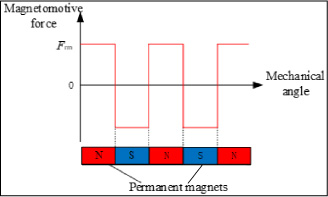
Diagram of magnetomotive force of PMs.
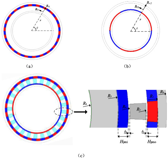
Structure diagram of CMG. (a) Magnetic flux density produced by the low-speed rotor permanent magnet; (b) magnetic flux density produced the high-speed rotor permanent magnet; (c) geometric parameter symbols of CMG.
The magnetic flux density in air gap is a function of radius r and angle θ ⋅ B r (r, θ) is the magnetic flux density of air gap magnetic field. Figure 4 shows the schematic diagram of air gap magnetic field function B (r, θ) without MPs.
Without considering the work of MPs, the magnetic flux density is produced by low-speed rotor. Assuming that the corresponding magnetic flux density is B
1, the radial component generated in the air gap with radius r is B
r1(r, θ), and the tangential component is B
θ1(r, θ). After Fourier decomposition, their expressions can be respectively expressed as:
Similarly, when the magnetic flux density is only produced by high-speed rotor, the radial component B
r2(r, θ) and tangential component B
θ2(r, θ) of magnetic flux density in the air gap are expressed as:
∙Air gap magnetic field with MPs
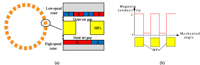
Diagram with MPs. (a) CMG with MPs; (b) diagram of MPs’ magnetic conductivity.
The magnetic conductivity in the air gap with MPs is shown in Fig. 5(b), after Fourier decomposition, it can be expressed as:
After being modulated by the MPs, the radial component and tangential component of the low-speed air gap magnetic field can be respectively expressed as follows:
The MPs of the CMG brings about the change of air-gap reluctance. From Eqs ((6)) and ((7)), it can be known that the magnetic field space harmonic pole pairs of the low-speed rotor permanent magnet can be expressed as:
The relationship between the rotational speed of the magnetic field space harmonics ω
m, k
and the rotational speed of the low-speed rotor ω
out
is expressed as:
It can be known from Eq. (9) that due to the introduction of the MPs, the rotational speed of the spatial harmonics of the magnetic field changes after the modulation, resulting in a variable speed transmission. When m = 1, k = −1, the amplitude of harmonic content that can be generated by the modulated magnetic field space reaches the largest value, and the transmission torque is the biggest at this time. Therefore, the numerical relations among the pole pairs of the permanent magnets of the high-speed and low-speed rotors and the number of modulating pieces is p out + p in = Z.
Fixing the MPs, the transmission ratio of the magnetic field modulation type PM motor is express as:
The CMG model is modeled and analyzed by FEM. Figure 4(c) shows the geometric parameter symbols of CMG, the corresponding parameters are shown in Table 1.
Basic parameters of CMG
Basic parameters of CMG
∙Air gap magnetic field distribution
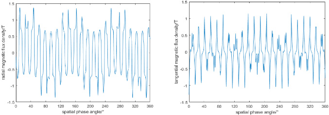
By simulating the radial and tangential components of the magnetic flux density of the inner and outer air gap magnetic field, the distribution waveform of radial and tangential magnetic flux density vectors in the inner air gap within 360° circumference is shown in Fig. 6.

Distribution waveform of magnetic flux density in inner air gap. (a) Radial component of magnetic flux density; (b) tangential component of magnetic flux density.
It can be seen from Fig. 6(a) that the inner air gap magnetic field shows three magnetic field cycles under the action of three pairs of inner rotor permanent magnets. There are some magnetic field peaks in the waveform due to the existence of MPs. In contrast, the waveform of tangential component in Fig. 6(b) is more complicated, because the tangential component of magnetic flux density is mainly affected by the interface between MPs and air gap. On these interfaces, the tangential component changes rapidly which resulting in more peaks.
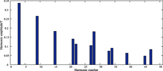
Fourier analysis of radial components of magnetic flux density in inner air gap.
Figure 7 shows the Fourier analysis spectrum of the radial component of magnetic density in the inner air gap. As can be seen from Fig. 7, the maximum harmonic number of the radial component of the magnetic density in the inner air gap is 3 times, and the amplitude is about 0.337 T. This content is mainly composed of two parts: the fundamental component established by the high-speed rotor permanent magnet and the harmonic component of the fundamental wave of the low-speed rotor permanent magnet modulated by the MPs. Between 0 and 50 harmonic times, 12 obvious harmonic amplitudes can be observed. In addition to the maximum harmonic times of 3 times, they are 9 times, 15 times, 21 times, 22 times, 27 times, 28 times, 33 times, 34 times, 39 times, 45 times and 47 times respectively. The 22nd harmonic component includes the fundamental component established by the low-speed rotor permanent magnet and the harmonic component of the fundamental wave of the high-speed rotor permanent magnet modulated by the MPs. It and the 3rd harmonic component jointly complete the torque transmission on the high-speed and low-speed rotors.
Figure 8 shows the distribution waveform of radial and tangential magnetic flux density vectors in the outer air gap within the 360° circumference.
Distribution waveform of magnetic flux density in outer air gap. (a) Radial component of magnetic flux density; (b) tangential component of magnetic flux density.
Figure 9 shows the Fourier analysis spectrum of the radial component of magnetic density in the outer air gap. As can be seen from Fig. 9, four obvious harmonic amplitudes can be observed between 0 and 50 harmonic times, which are 3, 22, 28 and 47 times respectively. The maximum harmonic number in the radial component of magnetic density in the outer air gap is 22, and the amplitude is about 0.894 T. This content is mainly composed of two parts: the fundamental component established by the low-speed rotor permanent magnet and the harmonic component of the fundamental wave of the high-speed rotor permanent magnet modulated by the MPs. The third harmonic component includes the fundamental component established by the permanent magnet of the high-speed rotor and the harmonic component of the fundamental wave of the permanent magnet of the low-speed rotor modulated by the MPs. The 3rd and 22nd harmonic components jointly complete the torque transmission on the high-speed and low-speed rotors.
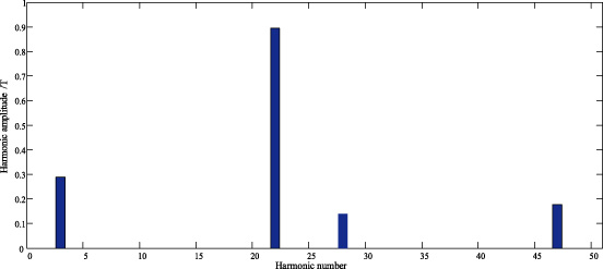
Fourier analysis of radial component of magnetic flux density in outer air gap.
∙Working peak torque of CMG
The high-speed rotor is set as the driving wheel, the MPs is fixed, and the low-speed rotor is set as the driven wheel to study the torque characteristics of the high-speed and low-speed rotors. The magnetic torque curve is shown in the Fig. 10.
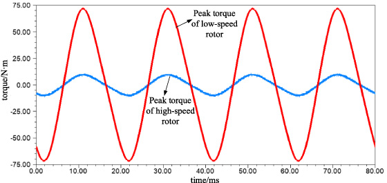
Magnetic torque curve of CMG.
The peak values of the high-speed and low-speed rotor torque curves represent the maximum torque that can be transmitted by the high-speed rotor and the low-speed rotor respectively, it can be seen from Fig. 10 that the peak torque transmitted by the high-speed and low-speed rotors are 9.5 N⋅m and 68.3 N⋅m respectively.
Torque density is one of the important indexes to measure the performance of generators. For CMG, it is of great significance to improve the torque transmitted per unit volume.
The output torque of the high-speed and low-speed rotors is closely related to the magnetic control effect of the MPs, and the modulation effect of the MPs is directly related to its shape parameters. The combination of RSM and PSO is used to optimize the three parameters of the radial height, inner diameter angle and outer diameter angle of the MPs, which effectively improves the CMG torque transmission ability.
RSM based on BBD
The basic mathematical model of CMG optimization is expressed as:
The basic principle of the RSM is to solve the optimal response value of the variable to be optimized by constructing the polynomial function. Therefore, specific sample points can be selected by the RSM, the sample data can be analyzed by the FEM, and the approximate fitting function can be obtained by selecting the fitting function method.
In general engineering optimization, the RSM is usually constructed in the form of quadratic polynomial with cross terms. The model contains interaction terms and square terms is expressed as:
Because the fitting speed and accuracy of response surface are influenced by the distribution of sample points in the design area, how to select the appropriate sample points is extremely critical. The sample point design method of Box-Behnken (BBD) is applied in this paper. It not only requires fewer sample points but also can ensure the accuracy and availability of sample point distribution. Figure 11 is a schematic diagram of BBD distribution in the case of three variables and three levels. When selecting the sample points corresponding to the experimental parameter variables, the experimental data on three levels are taken as −1, 0, 1, which represents low level, center point and high level respectively. If each experiment contains three repeated sample points, the experiment times of the three-level method are 17, the experiment times of the four-level method are 27, and the experiment times of the five-level method are 46. With the increase of the level number, the experiment times almost multiply. Generally, the sample point selection method with the number of levels greater than 5 is not used. Therefore, it is quite necessary and beneficial to choose three levels and three parameter variables method to reduce the number of experiment times and analyze the data quickly and effectively.
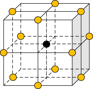
BBD distribution diagram.
After the response surface is fitted by a certain mathematical model, a certain optimization algorithm needs to be adopted to search for the optimal solution. Because the optimization objective function established by RSM is in the form of continuous polynomial, PSO algorithm can converge to the optimal solution at a faster speed compared to other algorithms [20], in addition, it has the advantages of simple principle and high search efficiency [21]. In view of the few optimization parameters in this paper, it greatly saves the calculation cost and resources. Therefore, PSO algorithm and RSM are combined for the optimization operation in this paper.
Like other population-based optimization algorithms, PSO is a random optimization technology based on population collaboration. It selects the concepts of “population” and “evolution”, then operates according to the individual fitness value. Finally, combining the individual optimal solution and the group optimal solution, the regional optimal solution is found through continuous iterations.
Assume that the CMG has D parameters to be optimized, and these parameters can be noted as a D-dimensional vector and form a D-dimensional parameter space. In the D-dimensional parameter space, m particles are randomly distributed, which stands for the MGs with different parameters. These particles can be noted as a m-dimensional vector
Variables and levels
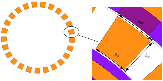
Shape parameters of MPs.
The radial height h sr , outer diameter angle θ out and inner diameter angle θ in of the MPs are selected as the variables to be optimized, and the peak working torque is taken as the optimization target. The RSM is introduced to study the relationship between the peak working torque and the three shape parameters of the MPs, and the parameters of CMG shown in Table 2 are optimized. Figure 12 shows the shape parameter diagram of MPs. During the optimization process, the structural parameters of the low-speed rotor should not change. Because the radial height of the MPs inevitably causes the change of the internal structural size, the air gap length of the high-speed and low-speed rotors and the amount of permanent magnet should be kept unchanged.
The experimental scheme of three factors and three levels is designed. The codes and levels of each parameter variable are shown in Table 3.
Variables x 1, x 2, x 3 correspond to the per unit values of h sr , θ out , θ in respectively. That is, x 1 = 1 corresponding to h sr = 13 mm, x 1 = −1 corresponding to h sr = 3 mm, x 1 = 0 corresponding to h sr = 8 mm; x 2 = 1 corresponding to θ out = 11.4°, x 2 = −1 corresponding to θ out = 3°, x 2 = 0 corresponding to θ out = 7.2°; x 3 = 1 corresponding to θ in = 11.4°, x 3 = −1 corresponding to θ in = 3°, x 3 = 0 corresponding to θ in = 7.2°.
Select specific experimental samples in the marginal area of the optimization parameter space, model and calculate these samples by using FEM, then solve the torque peak value corresponding to each sample. After applying the FEM to solve the peak torque of each sample, the corresponding results are achieved in Table 3.
BBD sample and corresponding peak torque
BBD sample and corresponding peak torque
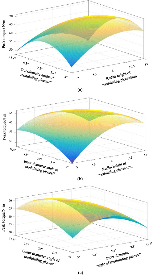
Peak torque influenced by h sr , θ out and θ in . (a) Influence of θ out and h sr on the peak torque of MG-PMSG. (b) Influence of θ in and h sr on the peak torque of MG-PMSG. (c) Influence of θ out and θ in on the peak torque of MG-PMSG.
By analyzing the 15 specific samples in Table 3, the corresponding relationship between the fitting response vector
According to the fitting function, the peak torque curves influenced by the radial height, outer diameter angle and inner diameter angle of the MPs are obtained as shown in Fig. 13.
It can be seen from Fig. 13(a) and (b) that the peak torque increases firstly then decreases with the increase of its radial height when θ in = 5.7°. Compared with the inner diameter angle and the outer diameter angle, the radial height has a more significant influence on the peak torque. Figure 13(c) shows that the torque peak value is obtained when θ out is between 8.2° and 9.2°, and θ in between 6.2° and 8.2°.
After the RSM is obtained, the PSO algorithm is then used to find the maximum peak torque and the corresponding variables’ value.
According to Eq. (11), establish the following optimization problem for the fitting function as:
The evolutionary algebra of PSO algorithm is set to 50 generations, the population size is 100, and the acceleration factors of c 1 and c 2 are 1.5 and 2.5 respectively. The algorithm optimization results are shown in Fig. 14.
It can be found that the optimized peak torque value is stable at 71.5712 N⋅m, and the corresponding radial height, outer diameter angle and inner diameter angle are: h sr = 9.69 mm, θ out = 6.2608°, θ in = 8.01°.
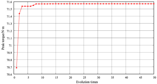
PSO algorithm optimization curve.

The FEM result comparison before and after PSO algorithm optimization.
Then use the FEM to model and verify the PSO optimization results. Figure 15 shows the output torque comparison before and after PSO algorithm optimization. Figure 15 shows that the optimized peak torque of outer rotor is 71.68 N⋅m, which is bigger than the results in Table 3. Compared with the torque before optimization, the low-speed rotor torque of the optimized CMG is increased by 4.95%. Thus, it has been proved that the proposed method can improve the CMG torque transmission ability effectively. In addition, by compared to the traditional methods, this method has fast Optimization speed, high accuracy, and less calculation time.
The MG-PMSG can be regarded as an external rotor permanent magnet synchronous generator which is mechanically and electromagnetically coupled with CMG. Its structural diagram is shown in Fig. 16, and the corresponding explosion diagram is shown in Fig. 17.

MG-PMSG structure diagram.
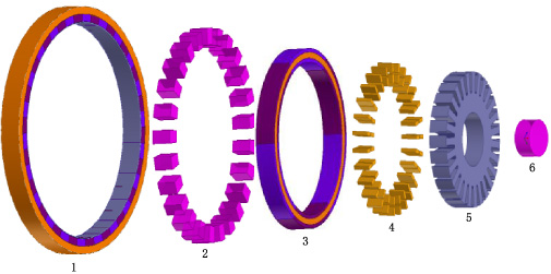
Explosion diagram of MG-PMSG. 1 Generator’s outer rotor and its inner surface mounted permanent magnet; 2 modulating pieces; 3 the inner rotor of the generator and its permanent magnets; 4 stator winding; 5 stator slot core; 6 shaft.
As the energy transmission mechanism of wave power generation, the CMG and its structural parameters will directly affect the transmission efficiency of wave power generation system. The design of permanent magnet synchronous generator determines the comprehensive performance of the system, such as stability, power generation efficiency and reliability. Considering the working principle and structural characteristics of CMG and permanent magnet synchronous generator, set the structure parameters reasonably, such as the number of magnetic pole pairs, the length of air gap, etc. At the same time, the internal magnetic field of MG-PMSG is analyzed by FEM, and the generator performances corresponding to the electromagnetic design schemes are checked.
The structure parameters design of MG-PMSG for WEC should fully consider the requirements of wave power generation. For example, compared with the inner rotor structure, the generator with the outer rotor structure is subjected to centrifugal force when rotating, which can be more structurally firm. The generator with fractional slot concentrated winding can effectively improve the sinusoidal degree of back EMF waveform, reduce the cogging torque, noise, and vibration of the generator. These structure designs help the MG-PMSG work better.
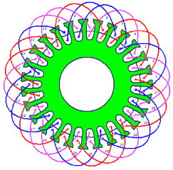
Stator winding connection diagram of generator.
Main parameters of MG-PMSG
Based on the above analysis, the MG-PMSG adopts the outer rotor permanent magnet synchronous generator with 6-pole 27-slot structure. The pole pairs of the permanent magnet of high-speed rotor are 3, and the pole distance is 9/2. The stator adopts fractional slot winding, and the number of slots per pole and phase is 3/2. The stator winding connection diagram of the MG-PMSG is shown in Fig. 18. The main parameters of MG-PMSG are shown in Table 4.
∙Static magnetic field analysis
The magnetic field lines and the magnetic density cloud map of the MG-PMSG are shown in Fig. 19.
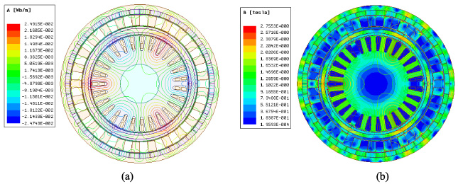
MG-PMSG magnetic field lines and magnetic density cloud distribution. (a) Magnetic field lines of MG-PMSM; (b) magnetic density cloud map.
It can be seen from Fig. 19 that the magnetic field lines of MG-PMSG are divided into three parts. One part of the magnetic field lines forms a closed path through high-speed rotor permanent magnet, the inner air gap, stator armature winding and high-speed rotor. The other part forms a closed path through low-speed rotor permanent magnet, the outer air gap, the MPs and the outer rotor. Another part of the magnetic flux forms a closed path through inner, middle and outer air gaps, which plays the role of magnetic torque transmission and electromagnetic energy conversion. In addition, there is a few magnetic flux leakages inside the MG-PMSG. This magnetic flux will not help torque transmission or energy transmission, but may cause energy loss and affect the operation efficiency of the generator.
The corresponding radial component distribution waveform of three-layer air gap magnetic flux density in an electric cycle is shown in Fig. 20.
Figure 20 shows that in the inner air gap, the magnetic flux density waveform is mainly established by 3 pole pairs permanent magnets of the high-speed inner rotor, so it presents a 3- pole-pairs symmetrical distribution. Secondly, the permanent magnets of the low-speed rotor will also affect the magnetic flux density. The two sides of the middle air gap are the high-speed rotor and MPs, so the permanent magnets of the high-speed rotor play a major role. The magnetic flux density waveform still presents 3-pole-pairs symmetrical distribution, but the harmonic components increase obviously. The magnetic flux density waveform of the outer air gap is mainly affected by the low-speed rotor, so its waveform is consistent with 22-pole-pairs. The fundamental wave components of magnetic flux density in inner, middle and outer air gaps are 0.9476 T, 0.4051 T and 0.8864 T respectively. The overall design meets the requirements and the magnetic circuit distribution is reasonable.
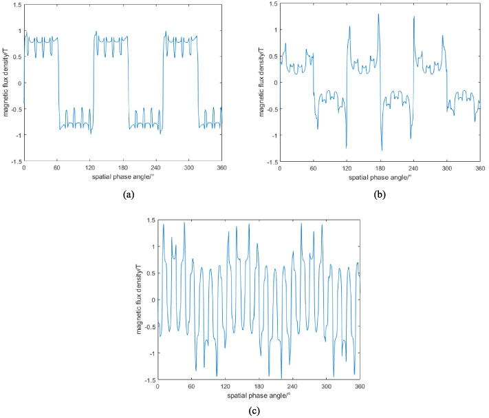
Radial component distribution of magnetic flux density in air gaps. (a) In inner air gap; (b) in middle air gap; (c) in outer air gap.
∙No load characteristic analysis
When the stator winding of the MG-PMSG is not energized, the no-load back EMF curve is obtained. Figure 21 shows the no-load back EMF curve of the MG-PMSG at rated speed of 136 r/min. It is three-phase symmetrical distribution, and the effective value is 287.4 V.
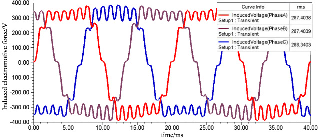
No load back EMF curve.
∙Load characteristic analysis
The external circuit shown in Fig. 22 is established and coupled with the finite element model of MG-PMSG for load characteristic analysis. The external circuit of the winding is set to measure the load response characteristics of the MG-PMSG under the rated load of 300 Ω. As shown in Fig. 22, LPhaseA, LPhaseA, LPhaseA and R3, R10, R11 are the inductances and resistances corresponding to the three phase windings of MG-PMSG respectively. R12, R13, R14 are the resistive load, and IUa, IUb, IUc and VIa, VIb, VIc are voltmeter and ammeter in the three-phase circuit respectively.
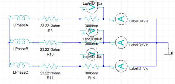
External circuit diagram of MG-PMSG.
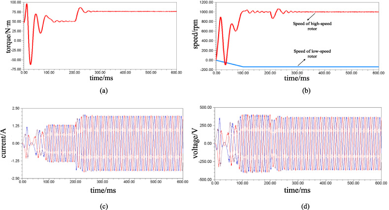
Given the initial speed, moment of inertia and damping coefficient of high-speed inner rotor are 0 rpm, 0.00126 kg⋅m2 and 0.000278 N⋅m⋅sec/rad respectively, and the steady state speed of low-speed rotor is rated speed 136 r/min, then the load torque and speed curves of the machine are obtained as shown in Fig. 23.
It can be seen from Fig. 23 that when the generator is started with load, the high-speed rotor gradually enters the steady state after 100 ms torque oscillation, and outputs the forward electromagnetic torque, and its speed reaches the rated speed of 1000 rpm.
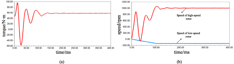
Load torque and speed curves. (a) Torque; (b) speed.
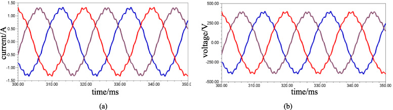
Load current and voltage curves. (a) Current; (b) voltage.

Losses curves. (a) Core loss; (b) eddy current loss.
Load variation curves. (a) Torque load; (b) speed; (c) load current; (d) load voltage.
The load current and voltage curves of the MG-PMSG are shown in Fig. 24. The effective value of load current is 0.889 A and the effective value of load voltage is 267 V, which meets the voltage design requirements.
The core loss and eddy current loss curves of the MG-PMSG are shown in Fig. 25. It is calculated that the effective value of core loss and eddy current loss in the stable state is 11.5 W and 13.73 W, meeting the efficiency design requirements.
∙Load disturbance analysis
Set the input speed as 136 r/min and the simulation time as 600 ms. In the initial process, the load is still 300 Ω. When the simulation time reaches 200 ms, the applied load is changed as 400 Ω.
In this condition, the related load torque, speed, load current and load voltage curves are shown in Fig. 26.
The results show that MG-PMSG starts from the stable operation state with a load of 300 Ω to another stable operation state. After a period of oscillation, the torque increases, the load current increases and the load voltage decreases, but the speed of the low-speed rotor is still stable at 1000 rpm, which still conforms to the transmission ratio between the high-speed and low-speed rotors.
Firstly, this paper introduces the basic structure and operation principle of CMG in detail from the perspective of magnetic field modulation, analyzes the modulation effect of MPs on CMG. In order to improve the torque density of CMG, a method by changing shape parameters of MPs with RSM and PSO algorithm is proposed. Based on the BBD, three factors of MPs: the radial height, the inner diameter angle, and the outer diameter angle of magnetizing pieces, are designed. Specific experimental samples are selected and calculated by FEM. By analyzing 15 specific samples, the corresponding relationship between response vector and the optimized parameter vector is obtained. According to the PSO algorithm, the maximum value of the fitting function is found, which is 71.57 N⋅m. Finally, optimized model is analyzed using the FEM and its peak torque is 71.68 N⋅m, which is consistent with the result of PSO algorithm. Compared with the torque before optimization, the torque of the optimized CMG is increased by 4.95%. Results show that the combination of RSM and PSO algorithm is an effective way to improve the CMG torque transmission capacity. Furthermore, the optimized CMG is integrated with PMSG to achieve a MG-PMSG. Corresponding finite element simulations of MG-PMSG are carried out, including static magnetic field analysis, no-load characteristic analysis, load characteristic analysis and load disturbance analysis. The results have verified the rationality of MG-PMSG design and application in wave power generation.
Footnotes
Acknowledgements
This work was supported by National Natural Science Foundation of China (No.51877148), Tianjin Natural Science Foundation (19JCZDJC32200) and 2021 Tianjin Graduate Scientific Research Innovation Project (2021YJSS019).