
Abstract
Electric vehicle (EV) wireless charging technology has recently attracted a lot of attention and has a broad potential for commercial application development. A fundamental performance indicator of wireless charging systems is efficient transmission. Magnetic coupling mechanism design and circuit parameters have the greatest effects on the transmission efficiency of the system. In this study, the output power and efficiency of the wireless power transfer (WPT) circuit were theoretically computed based on the LCC-type resonant network. Simulation studies demonstrate that the transmission efficiency and output gain deviate significantly from the expected value when circuit parameters are changed. To improve transmission efficiency, the optimal impedance configuration was created using a semi-controlled rectifier circuit. Based on electromagnetic field theory and equivalent magnetic circuit model, a new contactless transformer structure was optimized and created, and the new contactless transformer had a higher coupling coefficient. The coil offset had a greater impact on the transmission efficiency. The results indicate that within a certain distance, the coupling coil offset had no impact on transmission efficiency, and beyond that distance, the transmission efficiency was almost non-existent. Both the feasibility of the practical verification and the accuracy of the theoretical study were tested using a low-power wireless charging experimental setup. This paper provides design guidelines for wireless charging systems using circuit parameter sensitivity analysis and contactless transformer optimization design.
Introduction
WPT technology minimizes the use of cables and sockets, enables electrical and mechanical isolation, and has the advantages of ease of operation and wide application. Currently, WPT technology is extensively used in EVs, implantable medical equipment, portable home electronics and other applications [1–3]. Wireless charging technology for electric vehicles has excellent prospects for market application development and has received wide attention in recent years. Inductively coupled power transfer (ICPT) mode is a magnetically coupled structure with primary and secondary coil windings placed on the ground and in the vehicle, and contactless power transfer is achieved through high-frequency magnetic field coupling. ICPT systems have the advantages of high transmission power and long transmission distance, and are widely utilized in the field of EVs wireless charging [4,5].
At present, although some car manufacturers and research institutions have produced some wireless charging products for EVs, there are still some critical problems that need to be solved in high power, high efficiency and high performance wireless charging systems. It is well-known that deviations in electronic components are inevitable in the daily mass production process of electronic components due to factors such as cost constraints and manufacturing errors. For example, the accuracy of resonant compensation capacitors is 1%, 10%, 20%, etc. Therefore, both the resonant capacitor and the inductor in the wireless charging system have certain precision errors in the manufacturing process [6,7]. In addition, position distance offset fluctuation occur during the stopping process. The common primary and secondary side offsets of contactless transformers mainly include vertical direction offset, horizontal direction offset and spatial angle offset, as shown in Fig. 1. All these factors can lead to changes in the parameters of the wireless charging system [8]. Significant changes in the main circuit parameters can lead to a wide range of changes in output voltage and current as well as transmission efficiency characteristics, resulting in difficult control and sometimes even uncontrollable systems. Hence, the circuit parameters of the resonant network are an important factor affecting the performance of the WPT system. The contactless transformer structure determines parameters such as coupling coefficient, self-inductance and mutual inductance. Thus, the optimal design of the magnetic coupling structure is another key factor affecting the transmitted power and efficiency of the WPT system.
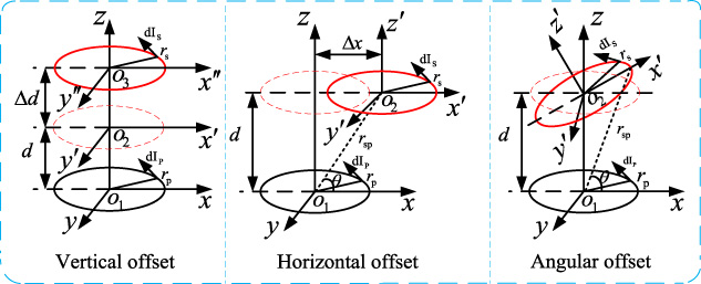
Coil space offset.
In order to solve the above mentioned problems, some researchers have discussed and studied in depth different aspects. The sensitivity of capacitance deviation and the influence of load and mutual inductance changes on the wireless charging circuits were studied in detail and it was concluded that the L-type impedance matching circuit can maximize the power and transmission efficiency [7]. The influence of load and transmission distance on transmission efficiency and output power of wireless charging circuits were analyzed [9]. In addition, a coupling distance region with high transmission stability can be obtained by load matching and an optimal balance of system output power and transmission efficiency could be achieved. The influences of load, quality factor and other circuit parameters on output characteristics of wireless charging circuit under the condition of coil space offset were explored [10–12]. A multiphase guideway induction charging system was proposed to generate relatively uniform magnetic field in a wider range [13]. The problem of lateral offset in dynamic driving process of electric vehicle was solved. In [14], the primary and secondary coils of unequal-sized transformers were designed so that the coupling coefficient remained constant when axial or lateral excursions occurred. Additionally, the optimization of the compensation capacitor was used to improve the transverse offset characteristics [15]. In [16–22], an equivalent magnetic circuit model of the magnetically coupled structure was introduced to optimize the contactless transformer structure and improve the transfer power and efficiency of WPT system. The above methods studied the effect of circuit parameters on the WPT system from different angles and used various methods to optimize circuit parameters and contactless transformer structure. These studies have improved the performance of wireless charging systems to a certain extent, but there are still some problems that deserve improvement.
In this work, the output power and transmission efficiency were theoretically calculated based on the equivalent circuit of an LCC-type electric vehicle wireless charging system. Firstly, the effects of load variation, coupling coefficient and resonant capacitance deviation on the output characteristics of the wireless charging circuit were simulated and analyzed. Secondly, based on the equivalent magnetic circuit model of the magnetically coupled structure, the structural design of the contactless transformer was optimized to enhance the coupling coefficient. Finally, a low power wireless charging experimental device was built to verify the feasibility and accuracy of the theoretical analysis. This provides a theoretical basis for the selection and parameter optimization of the compensation circuit.
The rest of this work was organized as follows. In Section 2, the output power and transmission efficiency were theoretically calculated based on the equivalent circuit of the LCC-type wireless charging system. The influence of circuit parameter sensitivity on external characteristics of wireless charging circuit was investigated in Section 3. The optimal configuration of impedance was achieved based on semi-controlled rectifier circuit control to improve the transmission efficiency. In Section 4, the influence of the contactless transformer coil offset on the performance of the wireless charging system was analyzed in detail and the structure of the contactless transformer was optimized. Then, a low-power wireless charging experimental setup was built to verify the accuracy of the theoretical study and the feasibility of practical verification in Section 5. Finally, conclusions are drawn in Section 6.
In inductively coupled wireless charging systems, contactless transformers suffer from large leakage inductance, small magnetization inductance, and low coupling coefficient and transfer efficiency. The power losses of the inverter circuit and rectifier circuit are not considered. In current study, the transfer efficiency mainly refers to the conversion efficiency of the input power of the resonant compensation network to the output power of the resonant network. For the primary and secondary of contactless transformers, compensation is often required to reduce the reactive power capacity of the system and to enhance the power transfer capacity. Common resonance compensation structures are first-order simple compensation networks network and higher order compensation network. The S-SP (LCC-type) compensation method combines the advantages of the S-S and S-P compensation methods. S denotes series resonant network, P represents parallel resonant network. The LCC-type resonant network can achieve a constant voltage output and the input equivalent impedance Z in is a pure resistive impedance to achieve zero phase angle (ZPA) of the converter output voltage and current [23-24]. In this work, the wireless charging LCC-type resonant compensation circuit was mainly analyzed.
To simplify the analysis of LCC-type resonant network circuits, the common contactless transformer equivalent circuit model as M model is shown in Fig. 2.
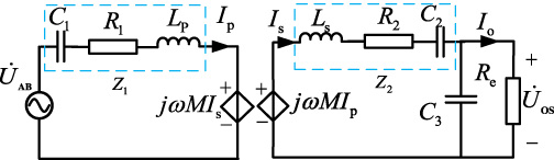
Equivalent models of contactless transformer M model.
In the LCC-type resonant network, the resonant capacitance and the self-inductance parameters of the primary and secondary coils were determined according to
According to Eq. (1), the expressions for the transfer power and efficiency of the resonant network could be obtained.
Efficient transmission is one of the important performance indicators of wireless charging systems. According to the efficiency calculation expressions in Section 2, it can be seen that the transmission efficiency was influenced by several parameters in the circuit. In order to improve the transmission power and efficiency of the circuit, it is necessary to analyze the relationship between the effect of circuit parameter variations on the transmission efficiency [25,26]. The effects of resonant capacitance error, load impedance and other parameter sensitivities on the transmission efficiency of wireless charging circuits were analyzed in this section.

The influence of the resonant capacitor error on the circuit: (a) variation of output voltage gain with compensation capacitor error; (b) variation of transmission efficiency with compensation capacitor error.
In the daily mass production process of electronic components, the deviation of electronic components is inevitable due to factors such as cost constraints and manufacturing errors. For instance, the accuracy of the resonant compensation capacitor is 1%, 10%, 20%, etc. Therefore, resonant capacitors and inductors in wireless charging systems are subject to certain accuracy errors in the manufacturing process [6,7]. The relationship curves of the output voltage gain and transmission efficiency with the compensation capacitance error are depicted in Fig. 3. In the figure, the horizontal axis 𝜒 indicates the error factor of resonant capacitor C 1, C 2, and C 3, i.e., the capacitance tolerance. It is the actual matching capacitance’s percentage divergence from the circuit’s theoretical resonant capacitance. |G v (ω)| and 𝜂out are the output voltage gain and transmission efficiency of the LCC-type resonant network. R e_min, R e_mid and R e_max indicate the smaller, middle and larger values of the output equivalent resistance of the resonant network, respectively. This annotation method was applied to the rest of the work. As can be seen in Fig. 3a, the parameter sensitivity of resonant capacitor C 3 had almost no effect on the output voltage gain in the LCC-type resonant network circuit. The parameter sensitivity of the resonant capacitor C 1 and C 2 had a significant influence on the output voltage gain. As can be observed in Fig. 3b, the sensitivity of the resonant capacitor C 1 parameter had almost no effect on the transmission efficiency. The sensitivity of the parameters of the resonant capacitors C 2 and C 3 has a great effect on the transmission efficiency. As the load resistance increased, the transmission efficiency decreased. In the case of the same error factor 𝜒 of the resonant capacitor, the selection of a suitable equivalent resistance R e would reduce the effect of the error factor on the output voltage gain |G v (ω)| and transmission efficiency 𝜂out.
Load sensitivity and parameter optimization design
The sensitivity of parameters (e.g., contactless transformer coupling coefficient and output equivalent resistance) also affects the transmission efficiency of the wireless charging circuit. The simulation calculation curve of the circuit varied with the coupling coefficient and output equivalent resistance sensitivity, as shown in Fig. 4. As the coupling coefficient of the contactless transformer increased, the transmission efficiency of the circuit increased. When the coupling coefficient k equaled to 1, the contactless transformer approached the ideal transformer and the transmission efficiency reached its maximum value. It could be concluded that there was an optimized output equivalent resistance R e_opt that maximized the transmission efficiency. When the impedance was small within a certain range, the transmission efficiency of the system was relatively high. As the impedance increased, the transmission efficiency decreased. The optimization of the coupling mechanism to improve the coupling coefficient was discussed in Section 4. The following describes the method to improve transmission efficiency by impedance matching.
Influence of coupling coefficient and output equivalent resistance sensitivity on circuit.
The above simulation analysis reveals that there was an optimal equivalent resistance for the LCC-type resonant network circuit to maximize the transmission efficiency. The extreme value of Eq. (3) is derived.
The optimal equivalent resistance R
e_opt could be solved from Eq. (4).
In order to improve the transmission efficiency by using impedance matching method, the wireless charging system based on semi-controlled rectifier bridge is shown in Fig. 5. S 1–S 4 formed the primary inverter circuit, and D 1–D 4 formed the secondary semi-controlled rectifier circuit, where D 1, D 3 are MOSFETs, and D 2, D 4 are diodes. U in is the high frequency inverter DC input voltage. The H-bridge inverter was used on the primary side and the semi-controlled rectifier circuit was adopted used on the secondary side. U bat is the secondary side rectified output voltage. R e is defined as the equivalent load of the secondary side rectifier circuit and the battery, and R t denotes the equivalent value of the internal resistance of the battery [27].

Wireless charging topology based on semi-controlled rectifier bridge.
The semi-controlled rectifier bridge adopted the phase-shift control method, and the rectifier output voltage could be obtained as follows
Assuming that the semi-controlled rectifier circuit losses were not considered, the rectifier circuit input power was completely converted to output power, i.e.
According to Eqs (6) and (7), the following equation could be obtained.
From Eqs (5) and (8), it was clear that the output equivalent resistance R e of the LCC-type resonant network circuit could always be kept at the optimum equivalent resistance value when the output load was changed, by controlling the rectifier circuit conduction angle 𝛼, so that the transmission efficiency could be maximized.
From Fig. 4, it was found that the transfer efficiency reached its maximum value when R e was very small. From Eq. (8), the output equivalent resistance R e reached a maximum value when 𝛼 = 180° was obtained. When R e < R e_opt, the transfer efficiency could not be maximized by any change in 𝛼. Therefore, in order to implement a semi-controlled rectifier circuit for maximum transfer efficiency control, the output equivalent resistance R e must be greater than or equal to R e_opt, i.e. R t ≥ R e_optπ2∕8. This is the rectifier circuit phase shift control to accomplish the best impedance matching method.
Obviously, the coupling coefficient of the contactless transformer directly affected the transmission efficiency. However, the coupling coefficient directly depended on the vertical transmission distance, horizontal offset distance, winding mode, coil turns ratio and wire diameter of contactless transformer. This section mainly discusses the variation law of the coupling coefficient with the offset distance of the contactless transformer in detail and further analyzes the efficiency characteristics of the wireless charging system.
Model of contactless transformer
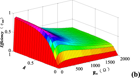
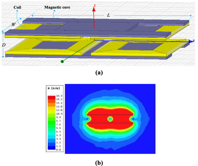
The wireless power transfer system has the characteristics of light weight, large transmission power and high coupling coefficient [17,18]. A three-dimensional (3D) diagram of the wireless power transfer system was constructed, as shown in Fig. 6a. The bottom structure was the transmitter of the excitation source on the primary side, while the upper side was the receiver on the secondary side. Based on the wireless power transfer system structure, the self-inductance and mutual inductance distribution area of the magnetic field structure were constructed, as shown in Fig. 6b. R
L1, R
L2, R
M1 and R
M2 are the equivalent reluctance of the transformer in different directions of self-inductance and mutual inductance distribution area. The expression for the coupling coefficient was obtained from the magnetic field distribution [17,18,28,29], as shown in Eq. (9).
The wireless power transfer system: (a) 3D diagram of the wireless power transfer system structure; (b) magnetic field distributed.
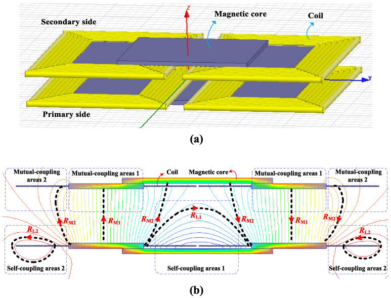
According to Eq. (9), reducing the equivalent reluctance R M1 and R M2 could improve the coupling coefficient. The simulation results indicate that adding a magnetic core around the transformer coil was able to improve the coupling coefficient. The structure optimization was carried out based on the wireless power transfer system. As shown in Fig. 7a, the 3D static field of a new contactless transformer was constructed by adding only one magnetic core without changing the winding structure of the original transformer. The magnetic field intensity distribution was simulated as described in Fig. 7b. It can be seen that the new contactless transformer had a smaller leakage field, the magnetic field intensity distribution was more concentrated and the mutual inductance was stronger. The height dimension of the magnetically coupled mechanism was H, the length was L, the width was W, and the turns ratio of the contactless transformer coil was n. The vertical air gap distance between the primary and secondary coils of a magnetically coupled mechanism was D, and the horizontal offset distance was x. The contactless transformer parameters are demonstrated in Table 1.
The new contactless transformer: (a) 3D diagram of the new contactless transformer structure; (b) magnetic field strength distribution.
The new contactless transformer had the same windings as the wireless power transfer system. A magnetic core was added to optimize the transformer structure in order to increase the magnetic field strength of the transformer. The magnetic field strength distribution of the new contactless transformer is shown in Fig. 8a. Based on the magnetic field distribution structure, an equivalent circuit of the magnetic circuit model was obtained, as shown in Fig. 8b. F
1 and F
2 are the equivalent magnetomotive force of the contactless transformer. According to the magnetic circuit model, the coupling coefficient k of the contactless transformer could be obtained:
Comparing Figs 6a and 8a, it was confirmed that in the two-dimensional (2D) static magnetic field distribution of the new contactless transformer, the magnetic field density area of the mutual inductance area 1 and the mutual inductance area 2 increased, while the equivalent reluctance R M1 and R M2 of the mutual inductance distribution area decreased.
Contactless transformer parameters

Magnetic field distributed and equivalent magnetic circuit of the new contactless transformer: (a) distributed self-coupling and mutual coupling areas; (b) the equivalent magnetic circuit model.
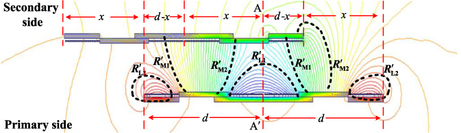
Distribution of magnetic lines during horizontal offset.
When defining the lateral dislocation of the primary and secondary coils, the relative positional relationship between the primary and secondary windings is depicted in Fig. 9.
Let 𝜙(x) = 0 get:
According to the above analysis, when the horizontal offset distance of the contactless transformer was

Relationship of coupling coil with offset distance: (a) relationship of coupling coil vertical distance offset; (b) relationship of coupling coil with horizontal distance offset.

Effect of coil offset on transmission efficiency: (a) transmission efficiency versus vertical distance; (b) transmission efficiency versus horizontal distance.
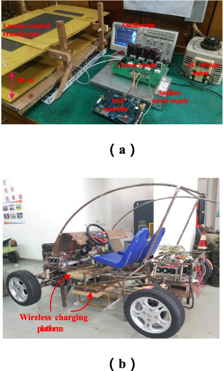
Experimental platform: (a) hardware experimental platform; (b) wireless charging platform for Evs.
In accordance with magnetic field strength simulation data, the fitted curve of the relationship between the coupling coefficient of the contactless transformer and the offset distance is described in Fig. 10. The fitted curve of the coupling coefficient with vertical distance offset is demonstrated in Fig. 10a. It can be seen that after optimizing the contactless transformer, the transformer coupling coefficient increased by 0.0773. The coupling coefficient of the contactless transformer was reduced as the vertical offset distance increased. The fitting curve of the coupling coefficient with the horizontal distance offset is depicted in Fig. 10b. The coupling coefficient of the contactless transformer was reduced as the horizontal offset distance increased. When x = 0, i.e., when the contactless transformer was aligned horizontally, the coupling coefficient reached the maximum. The coupling coefficient was zero when x = 163.02 mm, i.e., the displacement distance between the primary and secondary sides of the transformer was about
By modeling the magnetic circuit of the contactless transformer and simulating the calculations, the wide range of coupling coefficient variations caused by the primary and secondary coil offsets were theoretically analyzed. In order to increase the transmission efficiency of the effective offset distance, the transmission efficiency of the wireless charging circuit versus the contactless transformer offset distance is illustrated in Fig. 11. The efficiency versus vertical distance and the efficiency versus horizontal distance are respectively presented in Fig. 11a and Fig. 11b. In the figure, 𝜂out_simu and 𝜂out_meas are the the simulation calculation results and experimental measurement results, respectively. The results reveal that the coupling mechanism varied within a certain distance in the vertical and horizontal directions, and the coil offset had little effect on the transmission efficiency. When the offset distance exceeded a certain range, the transmission efficiency was almost zero.
As shown in Fig. 12, the wireless power transfer system was designed to further build a low-power hardware experimental platform and wireless charging platform for EVs. The simulation and experimental parameters are shown in Table 2. It should be noted that the experimental platform was merely to prove the correctness of the theoretical study and the validity of the practical verification.
Simulation and experimental parameters
Simulation and experimental parameters
The wireless charging circuit was added to the resonant compensation capacitor, and the resonant capacitor in the LCC-type resonant network was configured according to the parameters in Table 2, and the experimental waveform is demonstrated in Fig. 13. The experimental waveform of the extended plane U-type contactless transformer and the experimental waveform of the new contactless transformer are described in Fig. 13a and Fig. 13b, respectively. I A is almost in phase with U AB, illustrating that reactive power has been eliminated. The small phase angle of I A lagging U AB ensured ZVS of the full-bridge switches. Under the same conditions, the transfer efficiency of the extended planar U-type contactless transformer wireless charging circuit was 91.2%, and the transmission efficiency of the new contactless transformer wireless charging circuit was 94.4%. A comparison of the two contactless transformer efficiencies is shown in Fig. 14. The new contactless transformer had a 3.2% improvement in efficiency at full load.
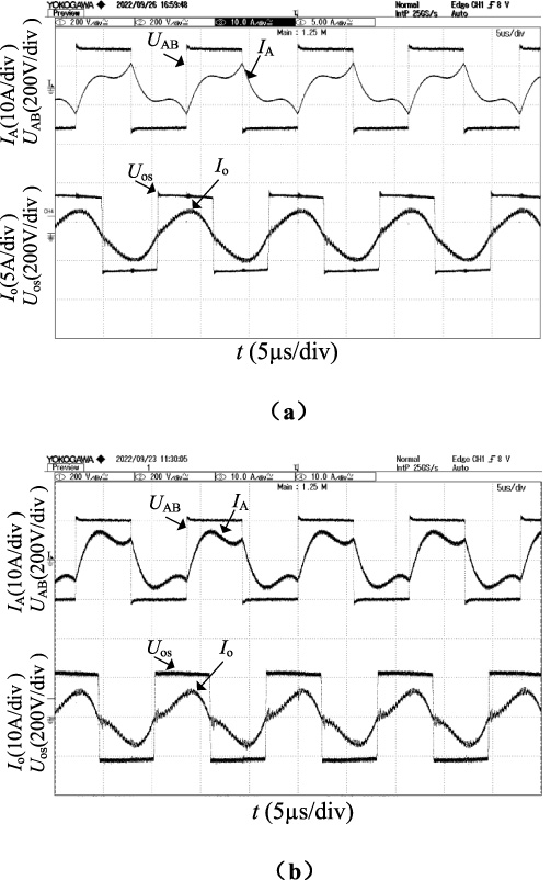
Experimental waveforms (R t = 60 Ω): (a) the wireless power transfer system; (b) the new contactless transformer.

Comparisons of efficiency.
Based on the LCC-type resonant network equivalent circuit of the wireless charging system, the output power and transmission efficiency were theoretically calculated. The simulation analysis shows that the changes of parameters such as equivalent load resistance and coupling coefficient had a great influence on the transmission efficiency. The optimal configuration of impedance was achieved based on the control of the semi-controlled rectifier circuit to improve the transmission efficiency. Simulations and experiments verified that the sensitivity of the resonant capacitance deviation made the transmission efficiency deviate from the expected value. Based on the electromagnetic field theory, a contactless transformer equivalent magnetic circuit model was established and a new contactless structure was optimized and designed with an improved coupling coefficient of 0.0773. Furthermore, simulations and experiments proved that the transmission efficiency and coupling coefficient varied with the horizontal and vertical offset distances of the coils. The results reveal that the offset of the coupling coil had little effect on the transmission efficiency within a certain distance range, and outside a certain range, the transmission efficiency was almost zero. A low-power wireless charging experimental setup was built to confirm the accuracy of the theoretical study and the feasibility of practical verification. The maximum transmission power of the experimental device reached 95.4%. In this study, circuit parameter sensitivity analysis and contactless transformer optimization design were provided for the design of wireless charging system. The effect of circuit parameter sensitivity on output power and coupling coil angular offset characteristics will be discussed in a future work.
Footnotes
Acknowledgements
This work is supported by the Education Department Project of Shaanxi Province, China (22JK0366), Research Center of Shangluo Distributed New Energy Application Technology and Shangluo Science and Technology Bureau Project (SK2017-46).