
Abstract
A comprehensive study of a ferrite magnet assisted synchronous reluctance machine (FMaSynRM) for the forklift applications by using open-source platform is introduced in detail in this paper including both modelling and electromagnetic design aspects. On the electromagnetism modelling side, this paper uses Elmer as the core and combines other open-source packages covering the preprocessing, solving, and postprocessing sections to build the finite element model of the FMaSynRM. On the electromagnetic design side of the FMaSynRM, this paper mainly discusses the single-double layer winding arrangement, rotor topology, and demagnetization performance. And the power, efficiency, and current maps of the finalized machine at different speeds and loads are estimated by the finite element method (FEM) using the open-source platform, which takes different control logics into consideration. Finally, the predicted results by FEM are verified by the tested results. The modelling method by using open-source platform and design procedure of the FMaSynRM presented in this paper can also be used in the design of other electrical machine types in the adjustable speed applications.
Keywords
Introduction
The ferrite magnet assisted synchronous reluctance machine (FMaSynRM) has recently attracted more attentions than ever before because of the relatively simple structure, low cost and high performance, especially in the fields of household appliances and electrical vehicles [1,2]. From the cost aspect, the FMaSynRM is cheaper than the rare-earth permanent machine because of the low cost of the ferrite magnet. From the electromagnetic performance aspect, compared with the induction machine, the power factor of the FMaSynRM is higher because of the usage of the ferrite magnet. Therefore, the FMaSynRM has become a better candidate compared to the existing solution (induction machines) for the next generation forklift application because of the relatively high efficiency and compact size.
To accurately and efficiently design an electrical machine, the finite element method (FEM) can hardly be avoided in both academia and industry as reported in [3,4]. The commercial packages such as ANSYS Maxwell, JMAG, Altair Flux, and COMSOL are almost the first choice for the modelling and simulation, which are highly reliable and have been used in many practical projects [5–8]. Most of the commercial packages are easy to use and the functions including the preprocessing, solving, and postprocessing for the modelling of the electrical machines are embedded inside, which means that other packages may not be needed and involved in the design process. They also have the transient-magnetic, magneto-static and time-harmonic solvers, which make them suitable for the modelling of different machine types including the induction machine, permanent magnet synchronous machine, and synchronous reluctance machine [9]. Nevertheless, because they all belong to the closed-source software, which means that it may not be flexible for the secondary development in some cases, especially for the scientific research area. In addition, they also have the drawback of high price for buying the license, which means they are not available for all the researchers and engineers.
Another solution to model the electrical machine by FEM is to utilize the open-source packages. Compared to the commercial solutions, the open-source package is free to use and suitable for the secondary development because the source code is open to the public. Nowadays, open-source packages like SMEKlib, FEMM, and Elmer appear to be used for the modelling of electrical machines [10–12]. FEMM is mainly developed by D. Meeker and has already been applied in the design of the synchronous reluctance machine, demagnetization performance evaluation of the brushless DC machine, and optimization of a doubly fed switched reluctance motor as reported in [13–15]. The main drawback of it is that it lacks the transient-magnetic solver. Therefore, it becomes difficult to get time-varying curves of the electromagnetic performance of the machine.
SMEKlib is an open-source library in Matlab developed by A. Lehikoinen and the most advantage is that it has the time-stepping transient solver, which makes it suitable for the induction machine’s modelling because the induced eddy current is involved (the time-harmonic solver can also be used for the initial design of the induction machine) [10]. However, the 3D solver is still under developing at the moment.
Another popular open-source package is called Elmer, which was initially developed by CSC-IT Center for Science together with some universities and companies in Finland since 1995 [16]. It is developed as a universal multi-physical solver and after more than 25 years’ development, it starts to be used in the field of the electromagnetic design of the electrical machine. J. Keränen et al. have successfully modelled the induction machine equipped with the squirrel cage and the rotor skew is also considered by the multi-slice method [17]. P. Ponomarev has simulated a permanent magnet synchronous machine in 3D and comparison has been made with the commercial packages as reported in [18]. The results show that errors of the average torque, maximum flux density, and magnets’ eddy-current losses solved by them always stay within 3%. Recently, M. Zaheer et al. have used Elmer to model the losses of an induction machine at different speeds and the simulated results are verified by the experiment [19].
In this paper, a comprehensive study of a FMaSynRM for the forklift application by using open-source platform has been introduced in detail containing both the modelling and design aspects of the machine and the correctness of the simulation results are verified by the experimental results. The main novelty of this paper is to show a potential and reliable approach to design a variable-speed FMaSynRM by using open-source platform, which has not been reported in detail yet regarding both the design and modelling aspects. The idea and implementation of the modelling and design of the FMaSynRM can also be used for other similar electrical machine types in the adjustable speed applications, especially for the electrical vehicles.
Implementation of the modelling of a FMaSynRM by using the open-source platform
In general, the implementation of the modelling of an electrical machine by the FEM mainly includes the preprocessing, solving, and postprocessing sections. In most cases, all these sections are integrated in one package if the commercial solution is chosen. However, once the open-source solution is determined to model the machine, several packages covering the above-mentioned aspects need to be selected to cooperate with each other, which make the modelling process more flexible and customized compared to the commercial solution.
Figure 1 depicts the logic used in this paper for the modelling of a FMaSynRM with the open-source platform. It can be seen in the figure that several open-source packages are involved in the whole project. Before the solving stage, the solver setting file needs to be prepared well including: defining physical properties and setting solving properties. In this paper, the transient solver is employed and the simulation time for each case is about one electrical period. After the solving is completed, it comes to the postprocessing section. In general, the output data can be classified into the scalar data and vector data. The scalar data refers to the torque, voltage, current, etc., and the corresponding waveforms can be plotted by the open-source package or programming language like Python, Octave, Scilab, etc. The vector data refers to the magnetic flux density, magnetic flux strength, magnetic vector potential, etc., and the corresponding isovalues, isolines, and arrows can be plotted by Paraview.
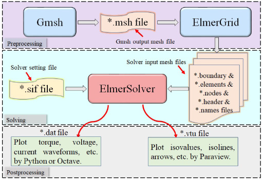
Flowchart for the modelling of a FMaSynRM by using the open-source platform.
Strictly follow the detailed procedure shown in Fig. 1, the FMaSynRM studied in this paper can be modelled successfully with the open-source platform. To check whether the solver works properly or not before the design stage, one possible way is to confirm the correctness of the no-load back-EMF, no-load flux linkage, and the no-load magnetic flux density distribution. Figure 2 shows the no-load back-EMF as a function of time of the FMaSynRM at 2000 rpm solved by the open source platform. It can be seen in the figure that the three phase voltages are balanced, although they contain some harmonics.

No-load back-FEM as a function of time of the FMaSynRM at 2000 rpm solved by the open-source platform.
Figure 3 shows the no-load flux linkage waveform of the FMaSynRM and it is estimated by the integral of the no-load back-EMF directly. Figure 4 shows the no-load magnetic flux density distribution of the FMaSynRM at 2000 rpm solved by the open-source platform. It can be seen in the figure that the magnetic bridge is highly saturated, which conforms to the initial design purpose of ensuring less short-circuit magnetic flux. The magnetic flux density of the rest part of the machine stays on a relatively low level, because the ferrite magnet in the FMaSynRM can only afford a low remanence. In addition, the mesh quality has also been displayed in Fig. 4 and there are 8957 nodes and 17097 surface elements in total for the model, which takes about 4.3 minutes to accomplish the simulation for 100 time steps per model tested on a computer equipped with Intel i5-10210U, 16 GB RAM. All in all, by considering the results shown in both Fig. 2 and Fig. 4, it can be regarded that the modelling logic and the corresponding solver setting mentioned in Fig. 1 should be solid and reliable.

No-load flux linkage as a function of time of the FMaSynRM at 2000 rpm solved by the open-source platform.

No-load magnetic flux density distribution of the FMaSynRM at 2000 rpm solved by the open-source platform.
In the section, the implementation of the modelling of a FMaSynRM with the open-source platform which involves several open-source packages has been introduced from the preprocessing to the postprocessing aspects. The simulation results of the FMaSynRM including the back-EMF waveform and the filed plot in no load condition prove that the modelling procedure is correct, which is a prerequisite for the further design and study of the FmaSynRM.
The FMaSynRM studied in this paper is designed for the electric forklift application, which means that the machine should have a wide speed range and needs to be tuned to fit some specific operating points, especially the full-load climbing. The required torque at full-load climbing is about 178 Nm at 720 rpm with the maximum loaded weight of 2.5 tons and a 20% reserve is selected in the design, so in the final design the maximum torque is about 220 Nm.
Table 1 lists the main parameters of the FMaSynRM studied in this paper. The FMaSynRM can be supplied by either the lead acid battery or the lithium battery and the DC link voltage is 80 V. Theoretically, the ideal output voltage of the inverter should be about 62 V. In real projects, a typical voltage reserve ranges from 10% to 20% is always appreciated, therefore the final maximum line voltage in this design is about 52 V. The maximum output current of the inverter is about 400 A. The stack lamination material is M50W600G and the ferrite remanence is 0.335 T at 120 °C tested from a 10.00 mm × 10.00 mm square sample.
Parameters of the FMaSynRM for the forklift application
Parameters of the FMaSynRM for the forklift application
To make it easy to tune the machine’s performances, the single-double layer winding is used in this design, because the number of turns in series can be increased or reduced more flexibly compared with the traditional design. Figure 5 illustrates the schematic diagram of the single-double layer winding arrangement. It can be seen in the figure that the single-double layer winding is further modified from the traditional double layer short-pitch (coil pitch y Q = 8∕9) winding. To be more specific, the zones belonging to the same phase are combined into a single one and the coil pitch remains the same. By default, the number of conductors should be doubled in the single layer zone compared to the double layer zone as shown in Fig. 5. But it has been noticed that a smoother current linkage waveform with a higher fundamental winding factor can be obtained if the number of turns in different zones is tuned in the right way. After the optimization, it has been discovered that the design requirements can be meet when the number of turns per half slot is around 9.
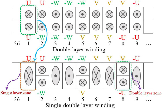
Schematic diagram of the single-double layer winding arrangement.
Figure 6 shows the single-phase current linkage waveform, current linkage spectrum, and harmonic winding factor of the single-double layer winding with NS = 17 conductors (per slot) in the single layer zone and N D = 9 conductors (per half slot) in the double layer zone. And each single-turn coil in the figure is injected with 1 A current. Because the distributed winding is used, the current linkage waveform appears to be a stepped sine wave, which contains two pole pairs. The corresponding single-phase current linkage spectrum shows that the fundamental is 1.202 A and the total harmonic distortion (THD) is 23.48%. Besides, the fundamental winding factor is 0.9622, which is an acceptable value for most cases.
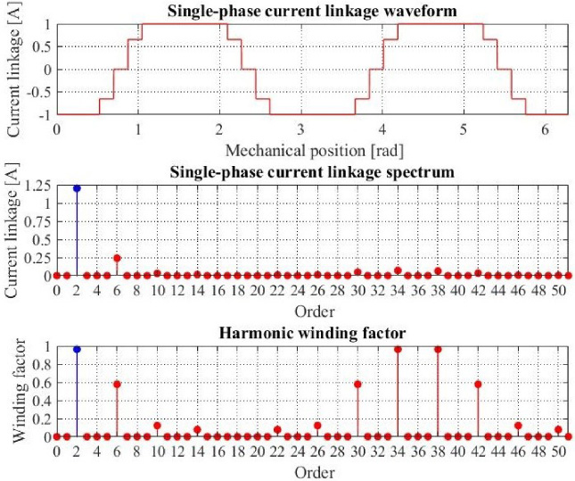
Single-phase current linkage waveform, current linkage spectrum, and harmonic winding factor of the single-double layer winding with N S = 17 conductors (per slot) in the single layer zone and N D = 9 conductors (per half slot) in the double layer zone.
Figure 7 illustrates the three-phase current linkage waveform and current linkage spectrum of the single-double layer winding. It can be seen in the figure that the waveform is smoother and more sinusoidal than that of the single-phase current linkage. The corresponding fundamental is 0.9865 A and the THD is 10.62%.
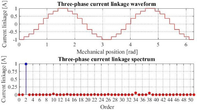
Three-phase current linkage waveform and current linkage spectrum of the single-double layer winding with N S = 17 conductors (per slot) in the single layer zone and N D = 9 conductors (per half slot) in the double layer zone.
Table 2 summarizes the winding performance comparison of different winding arrangements including the full pitch winding, short-pitch winding, and single-double layer winding. The number of conductors (per half slot) ND in the double layer zone is always 9 and the number of conductors (per slot) NS in the double layer zone varies from 17 to 20 as listed in the table. It can be seen in the table that the single-double layer winding is capable of providing a higher fundamental current linkage compared to the traditional full pitch winding. The traditional short-pitch winding can give either a high fundamental current linkage or a higher winding factor, but a tradeoff cannot be easily reached. When NS = 17 and ND = 9, the fundamental current linkage together with the winding factor reaches the highest and the THD maintains in the lowest level among all the winding types. Therefore, the winding design ends up with the single-double layer winding with NS = 17 conductors (per slot) in the single layer zone and ND = 9 conductors (per half slot) in the double layer zone.
Winding performance comparison of different winding arrangements
Figure 8 shows the rotor topology for the selected for the design of the FMaSynRM in this paper (the d and q axes are defined as the same as the permanent magnet synchronous machine). It can be seen that the rotor has four flux barrier and ferrite magnet layers. There are two main reasons to use this four-layer rotor topology. First, it has been noted that in this design the ferrite’s remanence is much lower that of the rare earth magnet, therefore the main output torque component belongs to the reluctance torque component instead of the ferrite magnet torque component. More layers (more flux barriers) may result in a higher saliency, which is capable of offering a higher reluctance torque component. Consequently, the torque density of the machine can be raised significantly.
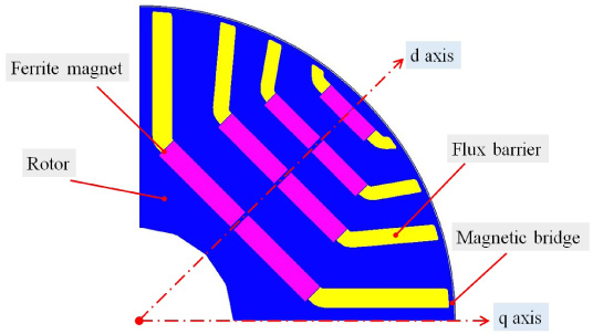
The rotor topology used for the design of the FMaSynRM (the d and q axes are defined as the same as the permanent magnet synchronous machine).
Another important reason is that more layers may increase the demagnetization performance of the FMaSynRM. In this design, the machine has been designed to have a wide speed range, which means that the ferrite magnet may withstand some high demagnetizing currents. So the demagnetization performance of the ferrite magnet needs to be checked beforehand. Table 3 lists the characteristics of the ferrite magnet applied in this design measured from a 10.00 mm × 10.00 mm square sample at different temperatures. Different from the rare earth magnet, the ferrite magnet may suffer the irreversible demagnetization in the low temperature situation. So it has been decided that the demagnetization performance of the FMaSynRM is checked at 20 °C. Besides, it can be assumed that the maximum demagnetizing current that the ferrite magnet may suffer is the maximum line current 400 A (230 A phase current) coming from the inverter side as mentioned in Table 1.
Measured characteristics of the ferrite magnet
Figure 9 shows the corresponding magnetic flux density distribution under the excitation of stator phase current i s = 230 A and electric current angle 𝛾 = 180° with reference to the d axis (the current is excited in the opposite d axis direction) at the room temperature of 20 °C. The minimum magnetic flux density in the ferrite magnet area is about 0.065 T, which is higher than the inflection point 0.05 T on the demagnetization curve at 20 °C where the irreversible demagnetization may occur. According to Fig. 9, it can be further concluded that the FMaSynRM has been designed well that it may not suffer the irreversible demagnetization in most cases.
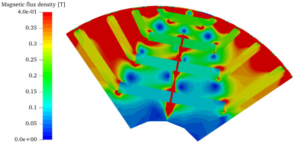
The magnetic flux density distribution under the excitation of stator phase current i s = 230 A and electric current angle 𝛾 = 180° (the current is excited in the opposite d axis direction) at the room temperature of 20 °C.
The design aspects of the have been discussed in detail including the stator winding arrangement, rotor topology, ferrite magnet, and demagnetization in the previous sections. The final dimensions of the FMaSynRM have been listed in Table 1. The loaded performance can be checked by the open-source platform.
Different from the virtual work method used in most of the commercial packages, the ElmerSolver uses the Maxwell’s stress tensor method to calculate the electromagnetic torque, which can be expressed as [20]
Figure 10 shows the electromagnetic torque as a function of time in the full-load climbing condition at 720 rpm solved by ElmerSolver (stator phase current i s = 172 A and electric current angle 𝛾 = 148°). The control logic used to approach the desired torque is the maximum torque per ampere (MTPA) control. The mean value of the torque is about 176.3 Nm, which is close to the design target at the full-load climbing (178 Nm, 720 rpm). It can be further seen in the figure that the machine has a high torque ripple and in reality, the stator skew is also used in the manufacture, which is capable of mitigating the torque ripple resulting from the slot harmonics. Figure 11 shows corresponding magnetic flux density at the full-load climbing. It can be seen that the highest magnetic flux density is about 2.0 T and located in the magnetic bridge and stator tooth tip areas. In addition, the magnetic flux density values in the stator tooth and stator yoke stay below 1.8 T and 1.6 T respectively, which are typical thresholds in the electromagnetic design of a machine. Last but not least, the flux lines traveling from the stator region to the rotor region is twisted in the figure, which means that the electromagnetic torque has been successfully generated by the interaction of the stator and rotor magnetic fields.
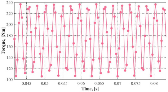
Electromagnetic torque as a function of time in the full-load climbing condition at 720 rpm (stator phase current i s = 172 A and electric current angle 𝛾 = 148°).

Magnetic flux density distribution of the FMaSynRM in the full-load climbing condition at 720 rpm.
In this section, the design part of the FMaSynRM have been introduced in detail including the stator winding arrangement and rotor topology aspects. The finalized dimensions have been presented and the loaded performance have also been verified by the FEM with the open-source platform.
To investigate the machine’s performance in the whole speed range of the FMaSynRM for the forklift application, the efficiency map becomes an essential and useful tool for evaluating the adjustable speed machine’s characteristics. The control logic of the FMaSynRM becomes important when it comes to the efficiency map. Figure 12 illustrate the control logic of the FMaSynRM involving the MTPA, maximum torque per voltage (MTPV), and field weakening (FW) control and more information about all these control methods is introduced in detail in [21]. To follow the trajectories shown in Fig. 12, the machine’s stator current is and stator terminal voltage us need to stay within the following constraints

The control logic of the FMaSynRM using different control methods.
To realize the control logic shown in Fig. 12, the d and q axis inductances are always needed. The accurate method to solve the d and q axis inductances considering the cross-coupling effects can be summarized as follows [23]
According to (4), by sweeping the stator current is and electric current angle 𝛾, the nonlinear d and q axis flux linkage and inductance maps as functions of d and q currents can be obtained, as shown in Fig. 13 and Fig. 14. It can be seen on the d axis inductance map that even the d axis current i d is kept as a constant, the d axis inductance L d will be changed once the q axis current iq varies. The similar situation is shown on the q axis inductance map, which means that the cross-coupling effects are considered correctly by (4).

Nonlinear d and q axis flux linkage maps as functions of d and q axis currents.

Nonlinear d and q axis inductance maps as functions of d and q axis currents.
Figure 15 shows the saliency map as functions of the d and q axis currents. It can be seen in the figure that the saliency changes from about 2 to 8 with the variation of the d and q axis currents and it decreases dramatically with the increment of the q axis current. Once the d and q inductances are acquired, the electromagnetic torque of the machine at any speeds can be estimated from the following equation
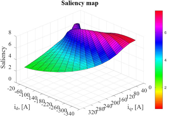
Saliency map as functions of d and q axis currents.
Take the control logic of the FMaSynRM presented in Fig. 12 into consideration, the electromagnetic torque as a function of the speed can be estimated by (5) and the corresponding torque curves are shown in Fig. 16. In the figure, the maximum torque is about 227 Nm and the FW starts at about 1000 rpm. The maximum torque at 3600 rpm is about 40 Nm. In addition, this figure also reveals that the machine is capable of providing a higher speed than 3600 rpm if it is needed.

Electromagnetic torque of the FMaSynRM as a function of the speed.
In this FMaSynRM the power losses mainly include the stator winding copper losses, iron losses, additional losses, and mechanical losses. The magnet eddy-current losses are ignored because the resistivity of the ferrite magnet is quite large, which means that there are almost no induced eddy currents flowing in the ferrite magnet. The stator winding copper losses PCu are estimated at 120 °C by the following equations
The iron losses can be estimated by the empirical model based on the Steinmetz formula, which is capable of considering the flux density harmonic effects and it can be expressed as [24]
Additional losses are assumed to be 0.5% of the input power as recommended in [20]. The prediction of the mechanical losses including the bearing friction and windage losses are always complicated although they can be estimated by some analytical formulas. It has been mentioned in [25] that the friction and windage losses can be determined more or less accurately and they occupy from about 0.2% to 0.8% of the output power at different speeds for synchronous machines. Therefore, the sake of simplicity, the mechanical losses of the FMaSynRM studied in this paper is assumed to be 0.5% of the output power.
After all the power losses are predicted, the efficiency of the machine at different loads and different speeds can be obtained as shown in Fig. 17, which considers the control logic presented in Fig. 12. It can be seen in the power map in Fig. 17 that the machine is capable of providing the output power up to 20 kW when it is approaching the FW area and the output power decreases with the increment of the speed. In addition, Fig. 17 also reveals that the machine has a relatively high efficiency (higher than 90%) operational area and the highest efficiency is achieved at about 2000 rpm.

Output power and efficiency maps as functions of the speed and torque solved by the open-source platform.
The FMaSynRM prototype has been manufactured with the finalized parameters as listed in Table 1. Figure 18 shows the experimental platform of the FMaSynRM and the corresponding rotor lamination has also been presented in the figure. Because the FMaSynRM is an adjustable speed machine, the output torque (power), efficiency, and current at different loads and speeds are mainly concerned in the test. Figure 19 shows measured output power, efficiency, and current maps as functions of the speed and torque.
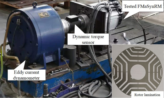
Experimental platform of the FMaSynRM.

Measured output power, efficiency, and current maps as functions of the speed and torque.
Compared the results in Fig. 19 by measurements and Fig. 17 by simulations, it can be noticed that both the power and efficiency maps are similar. The differences mainly come from the loss estimation errors including the iron losses, copper losses, additional losses, and mechanical losses by simulations conducted on the open-source platform. This problem also exists even the commercial packages are used, therefore the whole and procedure of the design of a FMaSynRM with the open-source platform can be regarded to be reasonable and reliable. Another reason is that the stator skew has not been considered in the modelling, but it has been used in the prototype.
Figure 19 also shows the stator phase current maps as functions of the speed and torque obtained by both simulations and experiments. It can be seen in the figure that the current maps are quite similar. To achieve the same amount of torque, a smaller simulated current is needed compared to the tested stator current. It is also resulted from the skewing effects because the stator skew will mitigate the amplitude of the fundamental air-gap flux density.
To further check the accuracy and effectiveness of the proposed modelling method, Fig. 20 shows the comparison of the tested and simulated stator line voltage error map as function of the speed and torque. The stator line voltage is selected as the compared target, because the stator current is the input value (which has already been compared in Fig. 19) to achieve the same amount of torque at different speeds in the modelling and the voltage is the output value. It can be seen in the figure that the maximum voltage error is less than 10%, which is acceptable for most of the engineering applications. In addition, the maximum voltage error only appears in the low torque range because the friction torque might be dominating in the low torque operating range.
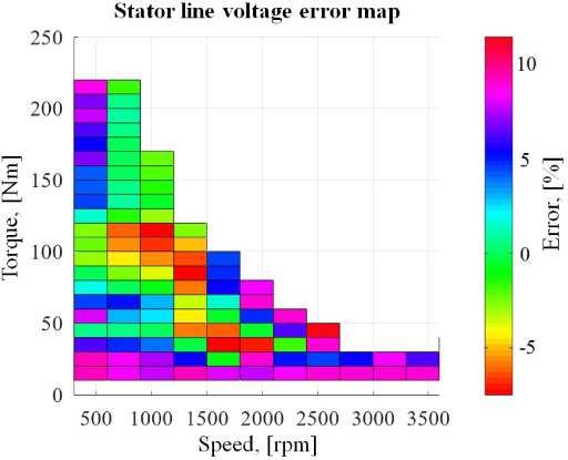
Comparison of the tested and simulated stator line voltage error map as function of the speed and torque.
A comprehensive study of a FMaSynRM for the forklift application by using the open-source platform is introduced in this paper. The FMaSynRM is fully modelled by using the open-source platform including the preprocessing, solving, and postprocessing aspects. To meet the design requirements, the design aspects of the machine including the stator winding arrangement, rotor topology, and the demagnetization performance have been discussed in detail. In the final, the power and efficiency maps as functions of the speed and torque are predicted by using the open-source platform, which takes the MTPA, FW, and MTPV control methods into consideration. The simulated results are verified by the measurement and the main difference between them comes from the error in the power losses estimation and skewing effects.
Last but not least, the modelling method by using the open-source platform and design procedure of the FMaSynRM presented in this paper can be considered to be reliable, and they can also be used in the design of the electrical machine types in the adjustable speed applications like permanent magnet synchronous machines for electrical vehicles.
Footnotes
Acknowledgements
This work is partially supported by Fundamental Research Funds for the Central Universities (JZ2021HGQA0198); Fundation of National Engineering Laboratory of Energy-saving Motor&Control Technique (KFKT202201); National Natural Science Foundation of China (51977055); Major Science and Technology Program of Anhui Province (201903a05020042).