
Abstract
Since Remote field eddy current (RFEC) detection technology is barely limited by the skin effect, it can realize the defect detection of large-thickness components. Whereas, the structure of the RFEC probe for the planar conductor is complicated, resulting in an oversized probe. This hinders the application and development of the RFEC testing technology. In this paper, finite element simulations and experimental verification are used to optimize the RFEC probe structure for flat conductors. The results have shown that the thickness of the magnetic shield is the dominant factor in achieving high performance of RFEC inspection of flat conductors. When inspecting both ferromagnetic and non-ferromagnetic flat conductors, cylindrical magnetic shields with appropriate thickness and appropriate excitation frequencies are preferred for improvement of RFEC testing.
Introduction
Because of the skin effect, conventional eddy current testing methods are limited to detection of surface defects in conductive materials. The pulsed eddy current (PEC) technique also has a large detection rate when detecting materials with high conductivity like copper, but is still affected by skinning effects, and PEC is not yet widely used in engineering, mainly because research on its transient response is still in its infancy. However, remote field eddy current (RFEC) detection technology can overcome the limitations of skin effect on deep defect detection, and has great application potential in nondestructive testing (NDT) field.
In recent years, RFEC has been widely used in inspection of pipeline [1–3]. The main trends in the development of RFEC technology are as follows: pulsed RFEC technology, shielding RFEC technology, U-shaped imitating pipe technology, and so on. In fact, RFEC phenomenon exists not only in pipeline, but also in flat conductive plates [4,5]. Therefore, it implements the through-wall evaluation of structural integrity, and has the higher detect capability of deep buried defects [6]. Sun et al. [7,8] expanded the applications of the RFEC technique from tube to nearly flat geometry plate with the help of specially designed probes, which were called the flat geometry RFEC probes, and several United States patents license has been obtained. For the reason of patent protection, the only public known information is that the probe should be shielded to make the RFEC phenomenon happen on the non-magnetic plate, but the detailed technique of probe structure design cannot be gotten. Moner a Faraj et al. [9] designed a rectangular vertical coil based on giant magnetoresistive sensor to detect defects on the conductor plate. He tests carbon steel and brass test blocks respectively, which proves that the probe is more effective for ferromagnetic materials. Repelianto et al. [10] designed a rotating butterfly probe with double-layer structure to detect the effectiveness of aluminum plate. The probe can detect defects in different directions, but did not carry out quantitative detection of defects.
She et al. [11,12] designed a flower type eddy current probe structure composed of one detection coil and multiple symmetrical excitation coils, which reduced the interference caused by lift off effect and increased the sensitivity of the probe. After that, they studied the structure of the far-field eddy current detection probe and found that the magnetic ring and magnetic shield can enhance the detection signal in the far-field eddy current detection. Wang et al. [13] designed a new RFEC probe for inspection and characterization of deeper defects in a flat conductive plate. However, the designed probe can only be used for ferromagnetic materials. Wu, Zhang and others [14] designed a deep penetration field trajectory probe, studied the effects of coil radius, pickup position and excitation frequency on eddy current penetration depth, optimized its performance, and applied the probe to realize the quantitative detection of stress corrosion cracks. The studies above focus on the probe or magnetic shielding structure. However, the realization of the REFC effect can not only be studied from the structure of the magnetic shield, should also focus on the thickness of the magnetic shield, the appropriate thickness can simplify the size of the detection probe, to achieve the purpose of easy to carry fast detection. Since RFEC probes for flat conductors still have many deficiencies, this paper is thus focused on shield thickness of the RFEC probe for inspection of ferromagnetic and non-ferromagnetic plates. The influence of the thickness of the magnetic shield on the realization of the RFEC phenomenon of the flat conductor is intensively investigated. The exciting coil in the probe was shielded to enhance the magnetic-field penetration through the plate, while the detecting coil and the region between two coils were not shielded. Simulations and experiments have been conducted to investigate necessary conditions for realization of RFEC effect of ferromagnetic and non-ferromagnetic plates.
Finite element simulation
Simulation model
RFEC testing technology has been widely used in the detection tubes. However, distinct differences can be found when planar conductors are inspected. As the traditional RFEC probe is applied to inspect a conductive plate, there is no restriction to energy diffusion along the direct coupling path owing to the absence of shielding effect of pipe wall. As a result, the direct coupling field above the plate is stronger than the indirect remote fields under the plate. Therefore, the RFEC phenomenon hardly takes place. To achieve RFEC effects in the flat plate, the shielding unit must be used in the RFEC probe to block the direct coupling fields above the plate.
The RFEC model is established in the finite element simulation software COMSOL Multiphysics 5.3 as shown in Fig. 1. A cylindrical exciter coil surrounded by a magnetic shield is placed on a metal plate in the air. In order to improve the calculation accuracy of the finite element simulation solution, the length of the conductive metal plate in the two-dimensional simulation model is 300 mm which is much larger than the size of the exciter coil, 4 mm. The simulation model mainly consists of four domains: the exciter coil, magnetic shield, metal plate and air domain. Table 1 shows the physical parameters of plates and the specific parameters are shown in the Table 2.
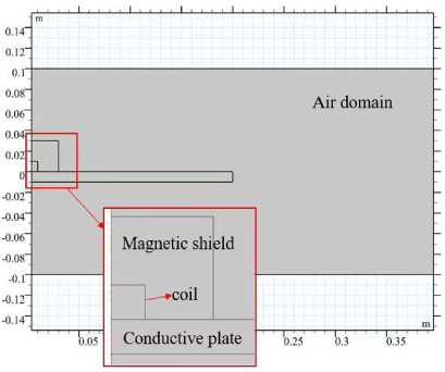
General model geometry.
Parameters of the subdomains in the FE model
Parameters of the defect
Using the alternating current/direct current (AC/DC) module in conjunction with the physical field chosen as the magnetic field, the RFEC model was simulated and solutions was analyzed in the frequency domain. According to Wang H’s research, the optimal excitation frequency for RFEC detection of ferromagnetic plates is 44 Hz [13]. According to the standard penetration depth formula, the standard eddy current penetration depth of the ferromagnetic material Q235 is approximately 2 mm when the excitation frequency is 44 Hz. In contrast, the RFEC optimum frequency of the non-ferromagnetic material Al6063 is about 1 kHz. Therefore, the excitation frequency was set as 1 kHz in the RFEC model of non-ferromagnetic plates. The software module is built on magnetic vector potential (A) and electric scalar potential (V ) formulation. It numerically solves the partial differential Equation (1) governing the EC phenomenon [15]:
According to the related theory of finite element solution, the area where the electromagnetic field is dramatically changed should be discretized with the dense mesh. From the boundary conditions of the electromagnetic field, it can be seen that the electromagnetic field will abruptly change at the interface between the magnetic shield and the air, the interface between the exciter coil and the air, the interface between the exciter coil and the metal plate, and the decomposition surface of the metal plate and air. Therefore, the grid of these areas needs to be refined. The complete grid contains 51,214 domain cells and 845 boundary elements. The number of degrees of freedom is 103,030. The specific mesh of the finite element simulation model is shown in Fig. 2.
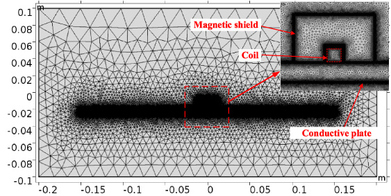
The typical triangular mesh in the model geometry.
In the RFEC detection process, the detector coil is mainly affected by the electromagnetic field energy of two penetrations through the measured conductive material. In the RFEC detection of the pipe, the pipe wall restrains the direct coupling of the exciter coil with the detector coil. Therefore, to realize the RFEC effect of the flat plate conductor, it is necessary to suppress the direct coupling between the exciter coil and the detector coil, so that the electromagnetic energy generated by the exciter coil can barely couple with the detector coil. Under the premise that the electromagnetic energy generated by the exciter coil is not directly coupled with the detector coil, the secondary penetration through the test metal plate is indirectly coupled with the detector coil.
To determine whether or not the thickness of the magnetic shield is a key factor in realizing the remote eddy current phenomenon is the main research content. Keeping the other parameters of the simulation model constant, the thickness of the magnetic shield is continuously changed, and judged if the RFEC effect is achieved. The following two aspects are analyzed to determine whether RFEC testing of flat conductors is achieved:
(1) According to the energy flow situation: in the RFEC test, the electromagnetic energy generated by the exciter coil needs to pass through the measured conductor twice and then form indirect coupling with the detector coil. Therefore, the energy flow of the finite element simulation model can be observed under the conditions of different magnetic shield thicknesses through the energy density map of the finite element simulation model.
(2) According to the detector coil response signal amplitude and phase characteristics: the detector coil placed on the surface of the metal plate under test, and close to the metal plate to be measured to obtain the detector coil from the exciter coil at different distances. The amplitude characteristic curve and phase characteristic curve of the coil response signal can be acquired. The RFEC amplitude characteristic curve rapidly decays in the near-field region while the attenuation speed in the transition region decreases. In contrast, the attenuation speed in the far-field decreases slowly while the phase characteristics of RFECs change rapidly in the transition zone.
Figures 3, 4, 5, and 6 show the normalized energy flow density plots for the finite element simulation model. The red arrows in the figure show the normalized Poynting vector [17]. Poynting vector represents the density and direction of energy flow during electromagnetic field propagation. Since the energy of the electromagnetic field decreases abruptly after passing through the metal plate, it can be normalized to facilitate the observation of the direction of the energy flow of the electromagnetic field. Figure 3 shows the Poynting vector diagram of the finite element simulation model when there is no magnetic shielding treatment. In the absence of a magnetic shield, the electromagnetic energy of the excitation field is not suppressed. The electromagnetic energy on the side of the metal plate directly spreads out, and can be directly coupled with the detector coil. The energy of the indirect coupling channel penetrates through the metal plate under the exciter coil, but is inhibited by the energy of the upper plate penetrating through the metal plate at the sub-surface of the metal plate. The field fails to penetrate through the metal plate twice. Therefore, when the exciter coil is placed directly on the metal plate under test, the RFEC effect of the plate conductor cannot be achieved.

Energy density diagram of finite element simulation model without magnetic shielding.
Figure 4 is a Poynting vector diagram of a finite element simulation model when a 4 mm thick silicon steel magnetic shield is applied over the exciter coil. Comparing Fig. 3 and Fig. 4, it can be seen that using a magnetic shield with a high magnetic permeability, the electromagnetic energy of the direct coupling channel out of the excitation field is restrained to a certain extent. This weakens the energy of the direct coupling channel penetrating the magnetic shield, so that the energy of the indirect coupling channel can enter the metal plate from the metal subsurface after passing through the metal plate once. However, the energy of the directly coupled channel at the surface of the metal plate is incapable of penetrating the metal plate twice. Therefore, magnetic shielding of the exciter coil can suppress the direct coupling of the electromagnetic energy of the channel, so that the suppression of the energy of the indirect coupling channel is reduced, which is beneficial to the realization of the RFEC effect.

Energy density diagram of finite element simulation model with 4 mm magnetic shield.
The thickness of the magnetic shield is further increased and its energy flow is analyzed. Figure 5 shows the Poynting vector diagram of the finite element simulation model with a magnetic shield thickness of 6 mm. Comparing Fig. 4 and Fig. 5, it can be seen that increasing the thickness of the magnetic shield can increase the suppression of the electromagnetic energy of the direct coupling channel. When the thickness of the magnetic shield increases to 6 mm, it is found that the energy of some indirect coupling channels can penetrate the metal plate twice. However, at this time, direct coupling channel energy interference still exists at the indirect coupling channel of the second-pass through metal plate.

Energy density diagram of finite element simulation model with 6 mm magnetic shield.
Energy density diagram of finite element simulation model with 8 mm magnetic shield.
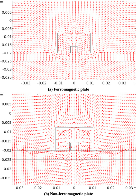
Figure 6 shows the Poynting vector diagram of a finite element simulation model with a magnetic shield thickness of 8 mm. Comparing Fig. 5 and Fig. 6, it can be found that when the thickness of the magnetic shield is increased to 8 mm, the energy directly coupled through is already completely suppressed in the magnetic shield. The energy of the indirect coupling channel passes through the metal plate twice and does not interfere with direct coupling channel energy after the indirect coupling channel energy passes through the metal plate twice. Therefore, according to the energy flow of the finite element simulation model, it is considered that the magnetic shield of high-permeability silicon steel material can effectively suppress the energy of the direct coupling channel of the excitation field. When the thickness of the magnetic shielding cover is 8 mm, the energy of the direct coupling channel of the excitation field is completely suppressed in the magnetic shielding cover, and the energy of the indirect coupling channel can penetrate the measured metal plate twice to realize the RFEC effect.
The response signals at different distances from the exciter coil were obtained when the magnetic shield thickness was 4 mm, 6 mm and 8 mm, respectively. The amplitude and phase are extracted and the amplitude and phase response curves are shown in Figs 7 and 8, respectively. Figure 7 shows the amplitude characteristics when the thickness of the magnetic shield is 4 mm, 6 mm and 8 mm, respectively. From Fig. 7(a), it can be seen that the overall trend of the ferromagnetic plate’s amplitude characteristic curve is basically the same regardless of different magnetic shield thicknesses. They quickly decrease and then turn around. However, the greater the thickness of the magnetic shield, the faster the amplitude signal decreases in the near field. This shows that for a ferromagnetic plate within a certain range, the greater the thickness of the magnetic shield, the better the suppression of direct coupled channel energy. As can be seen from Fig. 7(b), for the non-ferromagnetic plate, when the thickness of the magnetic shield is 4 mm and 6 mm, the amplitude characteristic curve monotonously decreases, there is no inflection point; when the thickness of the magnetic shield is 8 mm, its amplitude characteristic curve first rapidly decreases, then there is an inflection point, the amplitude decreases rapidly at the inflection point, and then slowly decreases.

Amplitude characteristic curves with different thickness shield.
Figure 8 shows the phase characteristics of the finite element simulation models with 4 mm, 6 mm, and 8 mm thickness of the magnetic shield. From Fig. 8(a), it can be seen that for the ferromagnetic plate, when the thickness of the magnetic shield is 4 mm, the phase characteristic curve slowly decreases, and the phase characteristics of the RFEC effect do not show sharp changes in the transition region. Therefore, no RFEC effect is achieved in the simulation model at this time, which is consistent with the analysis results based on the energy flow conditions. When the thickness of the magnetic shield is 6 mm and 8 mm, the phase characteristic curve has a certain degree of rapid change, but when the thickness of the magnetic shield is 8 mm, the phase characteristic curve changes much more than 6 mm. According to the comprehensive analysis of the amplitude characteristic curve and the phase characteristic curve, it is considered that when the thickness of the magnetic shield is 6 mm, the RFEC effect has been formed in the finite element simulation model, but the energy of the secondary penetrating metal plate is very weak. Combined with the analysis of the energy flow, the indirect coupling energy of the secondary penetrating metal plate is suppressed by the energy of the direct coupling channel. From Fig. 8(b), it can be seen that for the non-ferromagnetic plates, when the thickness of the magnetic shield is 4 mm, 6 mm, and 8 mm, the phase curves of the magnetic shields all show the characteristics of the phase characteristics of the RFEC effect drastically changing in the transition region. Therefore, when the thickness of the magnetic shield is 8 mm, both the amplitude and phase characteristics of the non-ferromagnetic plate exhibit the characteristics of RFEC effect, which indicates that the RFEC effect is achieved in the simulation model.

Phase characteristic curve with different thickness shield.
In summary, when the thickness of the magnetic shield is 8 mm, the Poynting vector diagram in the finite element simulation model of the ferromagnetic and non-ferromagnetic plates can observe that the electromagnetic energy passes through the tested plate twice. And at this time, both the amplitude and phase characteristics show the RFEC effect. Therefore, according to the simulation analysis, it can be inferred that the magnetic shield is made of a high magnetic permeability material to magnetically shield the exciter coil of the RFEC probe. When the thickness of the magnetic shield reaches 8 mm, the ferromagnetic and non-ferromagnetic plates can realize RFEC testing.
Flat conductor RFEC testing experiment system
The RFEC testing experimental platform construction for flat conductors testing is shown in Fig. 9. In the experimental process, the signal generator generates a sine wave with a frequency of 44 Hz and an amplitude of 20 V as the excitation signal is input into the exciter coil. The exciter coil is covered by a high magnetic permeability silicon steel magnetic shield (8 mm thickness) and placed on the surface of the metal plate (5 mm thickness) together with the detector coil. The distance between the exciter coil and the detector coil is 40 mm. The detector coil response signal is input to the signal input port of the lock-in amplifier, and the reference signal with the same frequency as the excitation signal is input to the reference signal channel of the lock-in amplifier.
Then, keep the distance between the exciter coil and the detector coil the same, and place the exciter coil above the subsurface defects whose height is 0 mm, 0.5 mm, 1.5 mm, 2.5 mm, 3.5 mm and 4.5 mm, and read and record the data processed by the lock-in amplifier.

RFEC testing experimental system.

Relationship between amplitude of RFEC response signal with different height subsurface defect in ferromagnetic plate.
In order to ensure the reliability of the experimental results, five sets of experimental data were collected and averaged to determine the relationship between response signal amplitude and phase with different height subsurface defects. Figures 10 and 11 show the relationship between amplitude and phase of the RFEC detection response signal and subsurface defect height of the ferromagnetic flat plate at the excitation frequency of 44 Hz. With the increase of the size of the defect, the amplitude and phase of the response signal obviously increase, and the response signal amplitude and phase have a good linear relationship with the subsurface defect height. Therefore, by using an 8 mm thick magnetic shield made of high permeability silicon steel, the RFEC probe exciter coil can be magnetically shielded to achieve RFEC testing of ferromagnetic plates. According to the amplitude and phase of the detector coil response signal at different height defects, the subsurface defects at different heights on the ferromagnetic plate can be quantitatively detected, which proves the reliability of the simulation analysis.

Relationship between phase of RFEC response signal with different height subsurface defect in ferromagnetic plate.

Relationship between amplitude of RFEC response signal with different height subsurface defect in non-ferromagnetic plate.
Figures 12 and 13 show the relationship between the amplitude and phase of the RFEC detection response signal with the subsurface defect height of the non-ferromagnetic plates at the excitation frequency of 1000 Hz. The amplitude and phase of the response signal increase monotonously with the height of the subsurface defect. According to the amplitude and phase of the detector coil response signal at different height defects, the different height subsurface defects on the ferromagnetic plate can be quantitatively detected. Therefore, by using an 8 mm thick magnetic shield made of high permeability silicon steel, the RFEC probe exciter coil can be magnetically shielded to achieve RFEC testing of non-ferromagnetic plates, which proves the reliability of the simulation analysis.

Relationship between phase of RFEC response signal with different height subsurface defect in non-ferromagnetic plate.
From simulation analysis and experimental results, it can be seen that using a magnetic shield made of high magnetic permeability silicon steel material, the RFEC exciter probe of the flat conductor is magnetically shielded. When the thickness of the magnetic shield reaches 8 mm, RFEC testing of the ferromagnetic and non-ferromagnetic flat conductor can be achieved. This greatly simplifies the structure of RFEC probes for flat conductors.
In this paper, the RFEC detection model of flat conductor was established by finite element simulation software. The energy density map of the simulation model with different thickness was obtained by finite element analysis. The response signals of the detector coil at different distances from the exciter coils under different magnetic shield thicknesses were obtained respectively, and their amplitude characteristic curves and phase characteristic curves were plotted according to their response signals. According to the energy density map and its amplitude and phase characteristic curves of the magnetic shield model with different thicknesses, when the thickness of the magnetic shield is 8 mm, the RFEC effect of the flat conductor can be achieved. Finally, a RFEC testing platform was set up to obtain the response signal of RFEC probes for detecting subsurface defects at different heights of the flat conductors, and the reliability of the finite simulation analysis was verified.
Footnotes
Acknowledgements
The work was supported by Key Laboratory of Nondestructive Testing (Nanchang Hangkong University), Ministry of Education under grant no. ZD201629001, Jiangsu University Blue Project Funding Project under grant no. 202042.