
Abstract
In the field of intelligent drive and sense, the traditional actuator can realize linear actuation and lacks sensing function. Therefore, a new sensing actuator is designed, which can not only output force and displacement, but also have thrust anti-torque sensing function. Firstly, the model of piezoelectric actuator is designed, and the geometric and mechanical models are established. Furthermore, the geometric relationship of mechanical and electrical parameters is analyzed. Secondly, the optimal included angles are determined after finite element analysis and optimization. Finally, the maximum output displacement is obtained through finite element analysis, and the maximum strain position is pointed out. Besides, the rotational stiffness is obtained. The results show that the modeling method and simulation results are accurate.
Introduction
The vibration of engine blades, helicopters, and wings, can damage the structures and disrupt their performance. With the rapid development of aerospace industry, all kinds of spacecraft are sent into space. In the space weightlessness environment, the harmful vibration seriously affects the technical indicators of spacecraft. For example, the micro vibration of satellite flexible antenna significantly affects the resolution of ground monitoring. Therefore, in the aerospace field, it is an urgent need to apply actuators to suppress the harmful vibration. Among many actuators, piezoelectric actuator is a special device which outputs displacement and force through applied voltage. It has the advantages of high energy conversion coefficient, less heating, and wide temperature range and so on. It is very suitable for the vibration control of flexible spacecraft. Meanwhile, piezoelectric actuators are increasingly used in industrial and research applications requiring high speed and accurate positioning at the micro and nano scales [1].
At present, various types of piezoelectric actuators have been designed. According to the inverse piezoelectric effect, Mystkowski used piezoelectric ceramics (PZT) to develop micro displacement actuators for small amplitude vibration suppression of flexible structures [2]. Xu designed a bionic inertial piezoelectric actuator, and discusses the bionic motion principle [3]. Zhang developed a new two-DOF inertial rotary motor using a two-dimensional piezoelectric actuator constructed on four bimorphs [4]. Dong designed a PZT inchworm actuator, and the actuator is mainly composed of a driving mechanism and two clamping mechanisms [5]. Besides, piezoelectric actuators are vigorously promoted in the aerospace field with reliability. Luo used a novel piezoelectric bending actuator to suppress the vibration of annular flexible structures [6].
Generally, the traditional actuator can output linear displacement and force [7–9]. However, in the measurement field of piezoelectric actuator, the output displacement is measured through external measurement equipment such as laser displacement meter. This external measurement equipment occupies a large space, and the measurement system is complex. Furthermore, the actuated object has reaction torque, and it is easy to damage the linear actuator. Therefore, in the field of piezoelectric actuator, it is necessary to design a new actuator which can not only output linear displacement and force, but also measure the output displacement in real time. In addition, the new actuator has torsion resistance functions, high sensitivity and high reliability.
For the measurement of output displacement, macro fiber composite (MFC) can be used to measure the strain and reflect the displacement. Compared with traditional piezoelectric materials, MFC overcomes many practical difficulties of monolithic piezoelectric ceramics, and has more stable performance and softer texture [10,11]. An has obtained good application in the strain measurement of annular flexible structure using MFC [12]. Moreover, the strain gauge can be used as a sensor [13]. For the torsion resistance functions, the spherical joint is designed in the actuator structure. Finally, the new actuator is a thrust anti-torque sensing actuator.
In this work, the structure of the sensing actuator is designed, and the geometric model and mechanical model are carried out. Then, the finite element model is established to calculate the optimal included angles. Finally, the location of the maximum output displacement and maximum strain is obtained through finite element analysis, and the rotational stiffness of the actuator is obtained.
Geometric model and mechanical model
Geometric model
A sensing actuator model is designed, and its structure is shown in Fig. 1. This is a rhombic structure with a PZT stack installed inside. A rod is installed on the structure through a ball joint and has the function of thrust anti-torque. The left end of rod outputs force and displacement. MFC patch is pasted on the flexible arm of rhombic structure to realize the sensing function. In addition, the maximum output displacement of actuator can be optimized from two included angles θ1, θ2 before deformation, and the maximum deformation of the actuator is obtained by finite element analysis. Therefore, the optimal structural parameters and the maximum strain position are obtained.

Actuator model.
Model initial parameters
Firstly, the deformation of the structure is analyzed. According to the angles determined by geometric model, the geometric analysis of the model is established to determine the relationship between the maximum output displacement and structural parameters,
Then the relationship between ΔL and other parameters is obtained by solving the equation,
The geometric relationship of displacement before and after deformation is
The mechanical model of the sensing actuator is analyzed after the PZT stack driving structure shown in Fig. 2. The deformation in the horizontal direction is the maximum output displacement ΔL. Due to symmetry, only half of the structures are analyzed here.
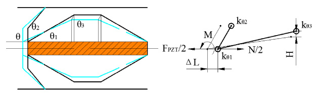
Schematic diagram of mechanical analysis.
The work by the external force is equal to the increasing potential energy of structure,
Therefore, the relationship between voltage, displacement and force of piezoelectric stack is
Based on the above geometric model, the finite element software ANSYS is used to analyse the maximum output displacement of actuator. By use of taking the angles of two flexure hinges as variable parameters, the maximum output displacement of the actuator at different angles is calculated. When 100 N is loaded on two inner surfaces of the actuator, Fig. 3 shows the output displacement changes with P1(θ1), P2(θ2).
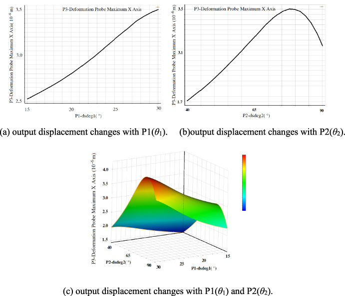
Output displacements at different angles.
Optimal output displacement
When the two angels are 80° and 30° respectively, the maximum displacement is output. Consequently, the included angles 80° and 30° are the optimal structural parameter.
Finally, ABAQUS software is used to analyze the output displacement, stress and strain of the actuator, when the input voltage of the piezoelectric stack is 120 V. Combined with theoretical analysis, the maximum displacement and strain positions are pointed out, and the structural stiffness parameters are obtained by simulation analysis.

Output displacement, stress and strain.
Figure 4 shows the maximum displacement ΔL is 2.515 × 10⁻² mm at the left end face of the actuator. The maximum stress is about 1.07 ∼ 1.34 × 10² MPa at the flexure hinge of the left end face. The maximum strain is about 2.8 ∼ 3.4 × 10⁻⁴ at the bottom of the long arm of the rhombic structure, and this position is suitable for pasting the strain sensor, such as MFC patch, strain gauge and so on. What is more, the angle Δθ1 of long arm of the rhombic structure has changed by 0.07 degrees. Therefore, when d33V is 38 μm/120 V, K p is 100 N/μm, it can be calculated that the rotational stiffness Kθ of the actuator is about 6.6 Nm/°. The obvious advantage is that the output displacement ΔL can be calculated directly as long as the rotational stiffness and input voltage are obtained.
In this paper, a new sensing actuator is designed, modeled and analyzed, and the optimized parameters are obtained. The simulation results show that the output displacement of the actuator is related to the included angle of the rhombic structure. The maximum stress is at the flexure hinge of the left end face. The maximum strain is at the bottom of the long arm of the rhombic structure. When the two angels are 80° and 30° respectively, the maximum displacement is 2.515 × 10⁻² mm. Finally, according to the above calculation results, the parameters of the actuator are determined to further guide the development of the sensing actuator.
Footnotes
Acknowledgements
This work is supported by the Natural Science Basic Research Plan in Shaanxi Province of China (No. 2022JQ-021) and Key Research and Development Plan of Shaanxi Province of China (No. 2020ZDLGY14-02).