



Abstract
In this paper, an efficiency improvement of a high-speed permanent magnet excited synchronous machine (PMSM) by the use of spot-welding as lamination packaging technology is realized. Welding, interlocking, clinching and gluing are typical technologies to manufacture electrical steel stacks of electrical machines. However, these processes deteriorate the magnetic properties of the steel sheets, thereby decreasing the overall efficiency of the machine. Variations of line-welding (six, eight, twelve, thirty two and forty) line welds and spot-welding procedure is performed and analyzed. A semi-physical iron loss separation approach is used to extract the IEM iron loss model (Eggers et al., IEEE Transactions on Magnetics
Introduction
For the construction of a mechanically stable magnetic core of an electrical ac machine, the electrical steel laminations must be firmly connected. Welding, interlocking, clinching and gluing represent the current state of the art of the mechanical connection of such thin steel sheets [14,15]. Each of the connecting processes leads directly to the deterioration of the material’s magnetic properties. Increased iron losses as well as a decreasing permeability of the electrical steel can be observed. The connection of the single lamination sheets by welding is a commonly used technology. In this process, the sheets are joined mechanically along a seam accompanied by an apparent dissipation of heat along the welding area. This local concentration of dissipated heat yields a thermal degradation and increase of the residual stress distribution inside the material[18,19]. The residual stress reduces the magnetizability of the electrical steel used due to the Villari-effect. In this paper, a method for improving the overall efficiency of a high-speed permanent magnet synchronous machine is discussed. The decreasing effects of the aforementioned weld process (spot-welding) on the eddy-current loss component of iron loss can be utilized for a high-speed operation, where most of the operations are at higher frequencies in the range 400 Hz–1000 Hz. A finite element simulation of the high-speed permanent magnet synchronous machine is performed and the analysis of the joining process with driving cycles has been done. The effects of welding have been reported [1–3] to lead to a significant magnetic deterioration of the sample of a ring core. These deterioration are in part, due to increase of the average grain size [13,17] in and around the welded area, and also due to the increase in residue stresses in and around the weld-point [5,8–12]. However, a comprehensive and systematic analysis of the welding process is still lacking. This paper studies the effects of different welding scheme such as spot-welding and line-welding on the iron losses and efficiencies of electrical machines. The simulated results will then be evaluated with vehicle data and driving cycles with view of understanding the exact extent of the influence of welding on actual application.
Experimental approach
Examined samples
Ring core samples welded with spot-welding and line-welding procedure were manufactured for this study. The ring core laminations have inner D i and outer D o diameters of 60 mm and 48 mm respectively (Fig. 1).
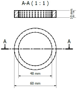
Geometry of the samples.
The height h of the examined ring samples is 9 mm, i.e. 30 ring laminations are joined together. The reference ring core is joined together with a conventional glue, so as to exclude the effects of the material degradation. The specific iron loss and magnetization emanating from this sample represents the electromagnetic properties of the laminated stack. The individual rings are laser cut to the aforementioned dimensions.
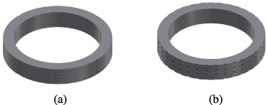
(a) Line-weld sample and (b) spot-weld sample.
The reference ring core is compared to other ring cores of different welding concepts (spot- and line-welding). The spot welded ring cores connects only two to three rings per spot at each instance Fig. 2b and 3b ). There is a minimum of 4 welds on each rings to ensure the mechanical stability of the motor. Less spot-welds can be used depending the mechanical requirements of the application.
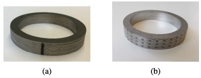
(a) Line-weld sample and (b) spot-weld sample.
For the welding process, a laser beam power of 320 W, focal position of 0 mm, resulting in a focal diameter of 400 μm and working pressure of 1000 mbar. Whereas the line-welds are performed at a weld speed of 0.5 m/min, the spot welds are instantaneous at a pulse duration of 70 ms. To ensure the comparability of the ring cores, all other weld process parameters are held constant. A multi-mode disc-laser with a focal length of 400 mm is used for this study (Table 1). Both spot- and line welding are performed with the laser.
Specification of the used laser beam source
In the measurement setup, during the sample preparations, the ring core dimensions (magnetic length, effective active area and effective active volume) are calculated according to DIN-IEC-60205 standard. During measurement the current on the primary winding induces a voltage response on the secondary winding. With the voltage response the magnetic parameters are derived according to DIN-IEC-60404-6 standard see Fig 4.
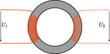
Measurement setup.
In this section, the extent to which each welding scheme contributes on the magnetic deterioration of the electrical sheets is quantified and analyzed. In Figs 5 and 6 the measured results of the specific iron loss and magnetization curves at 50 Hz is shown.

Specific iron loss at 50 Hz.

Magnetization curve at 50 Hz.
It can be observed, that in general welding leads to the degradation of the electromagnetic properties of the material. This is due to an apparent increase in the thermal energy that penetrates into the sheets. This energy leads to the change of the effective grain size and the deposition of residual stress at the affected area [4], thereby leading to the magnetic deterioration of the sheets. The level of deterioration increases with increasing number of weld lines. The spot welded sample is compared to the 8-line welded sample because of a similar effective welded area of 12.44 mm2. It is observed that the decrease of the magnetization of the welded samples, when compared to the reference sample is more pronounced at flux densities between 0.6 T and 1.5 T. At high frequencies, Figs 7 and 8 depicts a more significant deterioration of the material magnetic properties compared to the reference sample. This is due to the effects of the increasing grain sizes, which increases the excess and non-linear loss component.
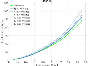
Specific iron loss at 1000 Hz.

Magnetization curve at 1000 Hz.
The non-dependency of the eddy-current loss from the effects of welding is observed, at the relatively slight percentage of deterioration of the material for both low and high frequencies. The difference in the deterioration of iron losses at higher frequencies compared to lower frequencies can be attributed to the grain size dependency of the excess loss component of iron loss. Furthermore, there was a slight change of the magnetization curves with increasing frequencies Figs 6 and 8 observed. Therefore, the effects of welding on the magnetization of the ring core is also frequency dependent. In Figs 9 and 10 is the depiction of deterioration of the iron loss of the investigated ring samples at a flux density of 1 T and frequencies of 50 Hz and 1000 Hz respectively. It can be observed, that line-welding leads to more deterioration compared to spot-welding. It can also be observed, that spot-welding and line-welding with 4 lines performed better than the reference sample. This effect will be evaluated in details, because it could be from the margin of error or due to changes in grain texture around the weld-point. The Figs 11 and 12 depicts the magnetization value of the investigated ring samples at a flux density of 1 T and frequencies of 50 Hz and 1000 Hz respectively. It can be seen, that the deterioration tendency is independent on the frequency. A higher level of deterioration of magnetization is observed compared to degradation of the iron loss. The total iron loss is defined as the sum of the hysteresis loss, classic eddy-current loss, local eddy-current loss component (excess) and non-linear loss component [6,7,16].
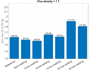
Specific iron loss changes at 1 T and 50 Hz.

Specific iron loss changes at 1 T and 1000 Hz.

Magnetization changes at 1 T and 50 Hz.

Magnetization changes at 1 T and 1000 Hz.
For the proposed FEM-simulation comes the motor topology. A high speed permanent magnet synchronous motor PMSM with four poles, an axial length of 98 mm and three-phased winding. The Fig. 13 depicts the torque-speed map of the attainable efficiency, when the material is welded with the line-welding scheme. In Table 2 is the data of the simulated machine shown.

Torque-speed map of the efficiency.
Data of the simulated machine

Torque-speed map of the WLTC-c3 driving cycle.

Torque-speed map of the city driving cycle.
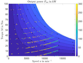
Torque-speed map of the highway driving cycle.
After modeling of the vehicle (here: Volkswagen golf), the operating points of the different driving cycles are calculated from the velocity-time characteristics of each driving cycle. The motor is incorporated so as to evaluate the motor characteristics with respect to the efficiencies and losses at the different operating points. An algorithm is used to calculate the operating points (torque and rotational speed) values equivalent of the driving cycles at an allowed maximum vehicle velocity of 180 km/h. Figures 14, 15 and 16 show the depiction of the operating points emanating from WLTC-c3, city and highway driving cycles respectively. These points show exactly the torque-speed characteristics of the respective driving cycle. After the calculation of the torque and rotational speed equivalent of the driving cycles, i.e. operational points and its distributions (Prob(Mcycle, ncycle, 𝛼)) are then incorporated into the loss map of the motor. Whereas 𝛼 represents here the utilized driving cycle. The mathematical description of the aforementioned process can be seen in Eq. (5).

Iron loss while operating the WLTC-c3 driving cycle.

Iron loss while operating the city driving cycle.
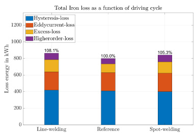
Ironloss while operating the highway driving cycle.
To analyze the effects of different welding schemes on the loss dissipation (efficiency) of an electric drive train, the ring core samples were electromagnetically measured. Loss dissipation attributed to a reference sample (ring packaged with a conventional glue), a spot welded and conventional line welded sample are compared and analyzed. A more visible deterioration of the magnetization was observed for all welded ring cores at flux densities between 0.6 T–1.5 T and at all frequencies during the electromagnetic measurements. For the evaluation of the results, a model incorporating the machine data with the application (golf-vehicle) and driving cycle characteristics is utilized. This modeling approach helps in mapping out of the knowledge on component level to system-wide investigations. Little or no influence of welding on the dissipated eddy current loss energy is observed, because the connection of only the outer surface has an insignificant influence on the induced eddy current. A higher performance improvement of the drive train was achieved at low and average speeds, due to the effects of average grain size at the welded area. Reduction of the excess loss component leads to a higher level of improvement due to its dependency on the grain size of the electrical steel grade. It can be seen, that a reduction of the hysteresis loss component with spot-welding in comparison with line-welding was due to the effects of residue stresses associated with welding. The improvement of the overall efficiency of the motor through spot-welding is due its lower iron loss compared to line-welding. The use of spot-welding procedure leads to less degradation compared to conventional line-welding procedure. This research shows, that a system-wide improvement of the motor can be achieved with welding procedural change (spot-welding) instead of line welding.
Footnotes
Acknowledgements
The work is funded by the Deutsche Forschungsgemeinschaft (DFG) 432930813 in the research group project “Elektromagnetische Bewertung und Quantifizierung von Schweißprozessen zur Paketierung von Elektroblechen”. Simulations were performed with computing resources granted by RWTH Aachen University under project rwth0922.