



Abstract
Due to the high requirements for performance of antennas in the modern communication system, more and more objectives need to be considered, which makes the antenna design unendurable time-consuming and hard to converge. To obtain the Pareto solutions for antenna design effectively and efficiently, a dual reduction method is incorporated in an improved multi-objective evolutionary algorithm based on decomposition (MOEA/D). To obtain information about conflicting objectives on the Pareto front, the size of the MOEA/D neighbourhood is dynamically adjusted; to improve the speed and accuracy of finding redundant objectives, PCA and Pareto impact ratio are used as dual objective-reduction criteria. Numerical results in solving the mathematical benchmark problems, an antenna array problem and Yagi-uda optimal design demonstrate that the proposed method can reduce redundant objectives and increase the convergence speed.
Introduction
The antenna is one of the most important components of a wireless communication system, which has a critical impact on the performance of the entire system [1]. In recent years, optimization algorithms are proposed for antenna designs and electromagnetic inverse problems [2–8]. In the development of 5G and 6G communication systems, essential objectives such as multiple operation bands, high gain, low loss, and small size need to be considered synchronously and complex structures of antennas are applied to achieve the goals. Therefore, modern antenna designs are often involved high dimensions on both objectives and decision variables, which leads to strong nonlinearity and local optimal solutions. As the objective number increases, most of the multi-objectives optimization algorithms are suffering three major problems: (1) the proportion of current non-dominated individuals in the population increases dramatically in the evolutionary iteration, which tends to make the algorithm in stagnancy; (2) the number of individuals required to search the Pareto front grows exponentially; (3) difficulty in visualizing the objective space causes inconvenience to decision makers. In addition, the objectives in the actual antenna design do not always conflict with each other, it is necessary to reduce the redundant objectives. In this regard, an improved multiobjective evolutionary algorithm based on decomposition (MOEA/D) method with a dual reduction method is proposed in this paper.
An improved MOEA/D with a dual objective-reduction method
MOEA/D divides a multi-objective optimization into several single-objective optimization sub-problems. The weight vector 𝜆 is used to aggregate the multi-objectives into single objectives, which is preselected and kept fixed in the evolutionary iterations. The sub-problems can be described as [9]:
In MOEA/D, neighbourhood vector
As aforementioned, the neighbourhood vector
To remove the redundant objective precisely, a dual objective-reduction method based on PCA [10] and Pareto impact ratio [11] is proposed. The current population and objectives are processed based on PCA first. The Pareto objective is scalarized and the covariance matrix V and the correlation coefficient matrix R are calculated [10]:
The matrix of eigenvectors is calculated based on matrix R obtained with (5) and sorted based on their corresponding eigenvalues. The principal components are designated with the matrix of eigenvectors. The value of ith element in the principal component reflects the contribution of ith objective to the principal component. Therefore, conflicting objectives can be obtained by selecting the elements with the larger difference value in the principal components.
To guarantee the redundant objectives are found properly, the conflicting objectives searched by PCA are analyzed using Pareto relation analysis [11]. Pareto impact ratio is used to measure the influence of one objective on the current Pareto solutions, computed as [11]:
The larger value of R f one objective could get, the more impact on the Pareto solutions caused by this objective. When the Pareto impact ratio is lower than a predefined threshold, it is considered that all the redundant objectives are found.
To facilitate the implementation the flow chart of the proposed method is demonstrated in Fig. 1 and the iterative process is given as follows.
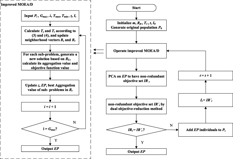
Flow chart of the proposed algorithm.
Step 1: Define and initialize global variables of the algorithm: m the number of objectives; t the iteration number;
Step 2: The improved MOEA/D algorithm is embedded in the main algorithm as a sub-program:
Define and initialize the local variables of MOEA/D: the weight vector 𝜆;
Calculate distances between weight vectors with (2) to obtain selection and replacement neighbourhood vectors
While i < Gmax, update neighbourhood vectors
Step 3: Implement PCA on EP the output from MOEA/D to have a non-redundant objective set IR
t
. IR
t
is further analyzed based on the Pareto impact ratio computed with (6) to obtain the final non-redundant objective set
Step 4: If
Step 5: Stop algorithm.
To verify the performance of the proposed algorithm, it is used to solve the DTLZ2 and DTLZ5 [12], the optimal design of the antenna array [13] and a microstrip Yagi-uda antenna optimization.
DTLZ test functions
DTLZ2 and DTLZ5 are used to test the performance of the proposed algorithm in optimization problems. DTLZ5 (I, M) is a test problem with redundant objectives, in which I determine the number of non-redundant objectives. The main parameters of the proposed algorithm are set as: population size N = 400, T C = 0.95, Rf0 = 0.85, Tmax = 100, and Tmin = 20. Table 1 compares the proposed algorithm to the PCA-NSGA-II [10] in terms of success rate in finding the redundant objective within 20 independent runs, as well as the inverted generation distance (IGD), which is used to measure the distance between a searched Pareto solution and the true one. Table 2 demonstrates the true non-redundant objectives and iteration numbers for the dual objective-reduction method and PCA to remove the redundant objectives correctly.
Comparison of success rate in finding redundant objectives and IGD
Comparison of success rate in finding redundant objectives and IGD
As shown in Table 1, the proposed algorithm can find the redundant objectives and has a higher success rate in finding the redundant objectives compared to PCA-NSGA-II. The advantage of the proposed method is more obvious as the number of redundant objectives increases. From the aspect of IGD values, the solutions obtained by the proposed method have the smallest IGD on solving DTLZ5 and competitive results on DTLZ2. From Table 2, it is known that the iterations needed by the proposed dual reduction method are less than PCA on finding non-redundant objectives which will save time consumption of the algorithm. In DTLZ5(3,10) and DTLZ(5,10), f1 − f8 and f1 − f6 are designed as non-conflict objectives, anyone in the non-conflicted objectives can represent the group. So it is equivalent to obtain f7f9f10 and f8f9f10, f2f7f8f9f10 and f6f7f8f9f10 in DTLZ5(3,10)and DTLZ(5,10) as final non-redundant objective set.
Comparison between dual objective-reduction method and PCA
To demonstrate the proposed method in antenna array designs, a 10-element linear antenna array is optimized based on the spacing and excitation amplitude of array elements. As shown in Fig. 2, the design variables are the distance d i between point sources and the excitation amplitude A i , i = 1, …,5. The antenna design has six objectives: directionality, side lobe level (SLL), deep zeros at 20°, 40°, 50°, and peak side lobe ratio (PSLR), recorded as f1, f2, f3, f4, f5, f6, respectively.
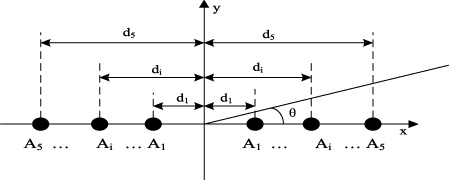
Schematic diagram of 10-element linear antenna array.
In this case study, the parameters of proposed method are set as: population size N = 150, T
c
= 0.95, Rf0 = 0.9, Tmax = 40, Tmin = 7. The original objective set is
The smallest and largest values obtained by the two algorithms are compared with the uniform array
Uniform antenna is taken as the benchmark solution; the optimization solutions searched by the proposed method and PCN-NSGA-II are compared. In Table 3, the smallest value and the largest value on each objective and the number of solutions better than benchmark solutions are given. From Table 3, it is shown that the proposed method has a strong searching ability. Table 4 gives one typical solution and its corresponding variables obtained by the proposed method and PCA-NSGA-II, and the solution obtained by the proposed method can dominate the one by PCA-NSGA-II, which proves the performance of the proposed algorithm.
Representative optimization solution for antenna arrays
The proposed method is used to optimise a microstrip Yagi-uda antenna. The structure of the microstrip Yagi-uda antenna is shown in Fig. 3, which is composed of an excitation element, deflector and reflection patch. The design variables are: (1) Larm represents the length of the excitation arm, 0. 21𝜆 < 0. 5Larm < 0. 38𝜆; (2) Ldef refers to the length of deflector, 0. 41𝜆 < Ldef < 0. 73𝜆; (3) D r represents the length of microstrip line, 0.22𝜆 < D r < 0.33𝜆; (4) D i (i = 1, …,5) represents the distance between deflectors, 0.13𝜆 < D i < 0.22𝜆. The central frequency is 2.45 GHz and the objectives are: return loss, wave ratio (VSWR), peak gain, front-to-back ratio, resistance and reactance in matching impedance, recorded as f1, f2, f3, f4, f5, f6, respectively.
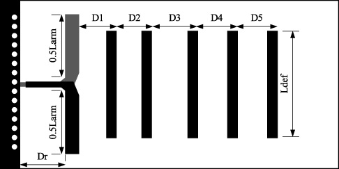
Schematic diagram of microstrip Yagi-uda antenna.
In this case study, the parameters of proposed method are set as: population size N = 100, T
c
= 0.95, Rf0 = 0.9, Tmax = 25, Tmin = 5. The original objective set is
Representative optimization solution for Yagi-uda antenna
To solve the redundant objective problem, this paper presents a dual objective-reduction method based on an improved MOEA/D. The DTLZ test function, the antenna array, and the Yagi-uda optimization problem show that the improved algorithm can find the non-redundant objective set and converge to the Pareto front.
Footnotes
Acknowledgements
This work was supported by the Natural Science Foundation, China under Grant No. 52077203 and the Fundamental Research Funds for the Provincial Universities of Zhejiang 2021YW06.