
Abstract
This paper discusses Design, Implementation and Control of Series Elastic Actuator (SEA). This model was mainly dependent on usage of mechanical off-shelf components which are weigh cheaper to purchasable models developed by companies. For an appropriate performance-to-cost component selection, cost-constrained design requires careful evaluation of important performance criteria. In addition, we used These models to create force and position tracking controllers that combine PID and disturbance observer control architectures model and practical based. SEA can be used as a compliant actuator, We have been keen to utilize a collaborative robot and tackle the safety issues that arise when robots and humans interact as well as the cost issue. As a result, The goal of this study is to show how to design and install hardware as well as implementing some software programs to produce a fully functioned University of Texas Series Elastic Actuator (UT-SEA).
Introduction
Firstly, The stiff actuation approach commonly used in factory room automation differs from the Series elastic actuation (SEA) approach. Series Elastic Actuator (SEA) relies under the passive compliant element actuator which have an elastic component used to sense impacts and obstacles [1]. To illustrate more, the used type of Series Elastic Actuator (SEA) in this study is designing a knee mechanism for legged robots. This approach has recently used to achieve compliant interactions and efficient gaits to study for robots in general and to this application in specific. Series Elastic Actuator (SEA) have several distinctive properties compared to rigid actuators including low mechanical output impedance, tolerance to impact loads, increased peak power output, passive mechanical energy storage and resistance to damage. These characteristics match the demands placed on legged actuation systems for robustness, high-power output, and energy efficiency [3]. As a result, SEAs have been widely adopted in the fields of legged robotics and human orthotics and powered Exoskeletons [2].
SEA mechanical design
Power source
Electric SEAs is powered by a DC Brushless motor which is the main source of the mechanical power. We used SANYODENKI DC Brushless Motor 90 watt (Actual Power) which operate at 34 Volts and 3.4 Amperes with no load speed 3000 rpm. The high motor speed produced by high bus voltage enables the use of a large speed reduction which increases both intermittent and continuous torque capability compared to designs with lower voltages and lower speed reductions knowing that Transient motor current is regulated by using a 32 kHz PWM motor driver. However, Calculations provided of the motor with the transmition mechanism of two pulleys with ratio 54:26 (This will be illustrated more in the next sub-section) indicated that a series inductance would keep transient current within reasonable values and in selection of motor for overall drive mechanism some factors must be considered. Firstly, The motor must be able to operate at the high-voltage-induced speeds mechanically. Motor bearing assemblies can only withstand a certain amount of speed before their service life is shortened, the high-speed centrifugal forces must be less than the strength limitations of the laminates and bonding agents used to build the motor rotor knowing that motor manufacturer usually specifies the maximum allowable motor speeds, putting in mind that Maximum allowable speeds for transmition mechanisms must be considered as well. Secondly, In Pulse Width Modulation (PWM) drives, increasing bus voltage causes current ripple, which can result in lower motor efficiency and heating inside motor.
Drivetrain
Many researchers have created rotary SEA systems that use a planetary gearbox to reduce speed, rotary or compression springs as the compliant element, and a bevel gear to transmit power. The majority of these designs are low-cost and straightforward to implement. Conversely, they have a low efficiency (60–70%) and are difficult to backdrive. Furthermore, the usage of gear teeth for power transmission can always cause torque ripple and backlash, regardless of the motor’s backlash, as well as having a limited torque capacity for their size. However Bevel gears can amplify these effects by adding extra backlash and friction loss, but they can’t completely eliminate them [6].
Mechanical Energy must be delivered from the motor to the joint with as minimal losses as possible to retain mechanical energy produced by the motor and method of motion gear transmition we discussed therefore we used a pulley/ball-screw speed reduction design was chosen similar to [4]. While using aluminium light-weight pulleys with the ratio (54:26) reduces the high motor speed to a speed more suitable for driving the ball screw with amplifying torque [1].
In [4], [5] and [6] uses ball screw for motion transformation from rotary motion into linear motion for prismatic SEA designs. Ball-screw mechanisms are widely known for their high efficiency. This high efficiency recorded (90%) where they are highly backdrivable, provide have a high tolerance for impact loads and do not introduce any torque ripples. As a result, ball-screw mechanisms are excellent candidates for designs for high-efficiency actuators. An important drawback of using a ball-screw mechanism is the fact that an output mechanism is needed for converting the prismatic output to rotation when necessary as mentioned in [5] as well as we experienced this practically. At the end We searched the market and used SFNU 1605-4 TBI Motion (1605) as our most suitable ball screw to be used inside our designed hardware.
Passive compliance
While series elastic actuation has been applied to other actuation technologies in [7,8] it is most commonly found applied to high-gear ratio electromagnetic actuators. The effects of series compliance complements this technology in particular largely because of the inertia-decoupling effects of the compliance, protecting the actuator drivetrain from harm due to high impact loads. Therefore restrict our focus of series elastic actuation to electromagnetic technologies.
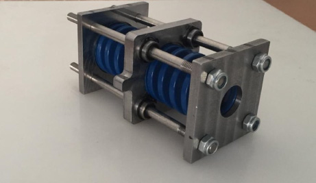
Actuation technology achieve promising results on University of Texas Series Elastic Actuator (UT-SEA). For example in [9] and [10] are all capable of walking over small obstacles and tolerating large exogenous perturbations. While SEAs perform well in all of the parameters we have examined (which will be seen in the modelling and control section), many of the actuators that power them can be improved in terms of power-to-weight, torque-to-weight, power-to-volume, force controllability, and efficiency. In Comparison to yobotics SEA UT-SEA is 16.67% better in power to weight ratio and 39% better in power to volume ratio and faster 17% than yobotics. Additionally, the single actuator performance of these systems is often not well characterized, making it difficult to directly compare these actuators. As a result, one of the main objectives of this research is to advance the state of the art and thoroughly define the performance of a single series elastic actuator while maximizing performance of compliant elements which is firstly a Chrome-Silicon Steel Blue Die Springs with Outer Diameter 50 mm, Shaft Diameter 25 mm, Length 64 mm, Stiffness 204 N/mm and a sesning element that detect the change in displacement of these springs by installing an absolute encoder as shown in Fig. 2.
Passive compliance hardware.
Reaction Force Sensing Series Elastic Actuator (RFSEA) Design places the spring between the motor housing and the chassis ground while Force Sensing Series Elastic Actuator (FSEA) the spring is connected in series between the motor and the end actuator (illustrations between two topologies are done in modelling and control section, modelling subsection). From a design standpoint there are several trade-offs between the two arrangements. There are numerous trade-offs between the two configurations in terms of design [11,12]. Because the compliant element does not have to travel with the load (in case of RF-SEA), it may be positioned statically behind the actuator or remotely situated, therefore RFSEA type actuators are more compact. Accordingly, the final mechanical model of the compliant springs alone is illustrated in Fig. 1.
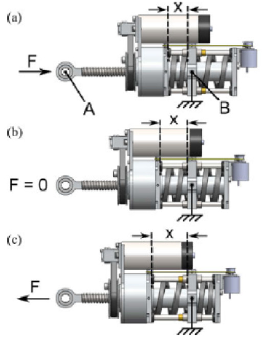
UT-SEA operation for a fixed-displacement variable-force scenario. Actuator displacement is defined as the distance between points A and B. This distance remains constant while spring detection (x) depends on actuator force.
The end Actuator of University of Texas Series Elastic Actuator (UT-SEA) can be manufactured in different forms, but lets define fundamental rigid parts that should exist. First of all, There should be a rigid link at the end of the ball screw, this link main objective to transmit linear motion from ball screw to the connected load. At the same time we were keen to manufacture these rigid links using aluminium alloy 3003 due to its lightweight and high strength. Also, another rigid link must be manufactured which act between the rigid link at the end of the ball screw and the robotic rigid arm at the end, and it has two pairs of concentric holes. However, this link main objective to perform general plane motion between the two connected links and we named this link as hand rocker link. Finally, we manufactured rigid link which we named Robotic Arm Head with 2 pairs of concentric holes as shown in Fig. 3. The first two concentric holes are used to be connected with the hand rocker link, where the other two concentric holes are to be interfered with a fixed shaft which is connected to feedback position encoder to know a feedback for the angle of actuator. Finally, The final hardware model is illustrated in Figs 3 and 4 (All these parts are manfactured on 5 Axes DMU50 CNC Machine).
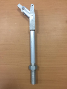
Robotic arm head with hand rocker link with rigid link at the end of ball screw.
UT-SEA Specifications
Weight
1980 g
Stroke
9 cm
Spring stiffness
204 N/mm
Torque constant
36.85 N.m
No load motor speed
3000 rpm
Operating voltage
34 V
Maximum current
3.4 A
Maximium actual power
90 W
Motor efficiency
0.7
The goal of this research is to accomplish two control objectives. The first is force control, which aims to achieve the behaviour of an ideal force source from the UT-SEA, which will aid in precisely tracking changes in the environment. Position Control is the second area of research to track the precisely the output joint angle and accurately following the rapidly changing joint positions. Position and force control are very related to each other. To achieve the best position control objective, force control should be accurate. And position control uses force control loop at the inner most loop of position control. Understanding the dynamics of the SEA is a must because the two control objectives demand for an excellent dynamic response. So, the first thing to do is defining an accurate model for SEA. Then, using this model to design the force and position controllers.
UT-SEA modelling
As discussed in last subsection, there are two fundamental structures for SEA according to the compliant element location with respect to the load, In RFSEA structure, the generated motor force (F m ) is switched with the spring (F k ) and there is a difference in both sprung mass (m k ) and output mass (m o ). Output mass (m o ) in RFSEA model includes rotor inertia, gearbox inertia and transmission inertia. Lumped sprung To keep the force controller design simple, a high output impedance configuration is employed. By grounding the actuator output, the model of the high output impedance configuration is shown. Because the suggested design is a prismatic, the focus will be solely on Reaction Force Sensing Series Elastic Actuator (RFSEA) type actuators. Structure of the RFSEA. The sprung mass (m k ) is exposed to the motor force (F m ) in this configuration in addition to (F k ) is the spring force and (F beff ) is the force due to viscous friction where (b eff ) = (b b ) + (b k ). Also, (F u ) is the disturbance force which are challenging to model. The force sensor in SEA is the spring. As a result, The spring in SEA acts as the force sensor. So, calculating the force at the actuator output (F o ) given the spring deflection (x) is the challenge for SEA force sensing and this is illustrated more in Fig. 5.
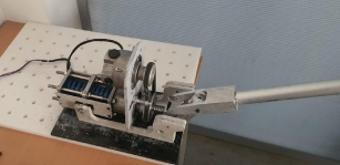
Another angle of final hardware model.
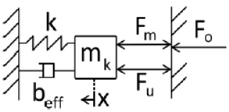
RFSEA high output impedance model. (F m ): Motor Force, (F o ): Output Force, (F u ): Disturbance Forces, (m k ): Lumped Sprung Mass, (k): Spring Constant, b eff : Lumped Damping ((b b ) + (b k )), (x): Spring Deflection.
From Newton’s second law states that the summation of forces exerted on a body is equal the mass of the body times the acceleration. The acceleration is the 2nd derivative of position so, in the total force equation as shown in (1)
Accurate force sensing for RFSEAs requires knowledge of k, b
eff
, m
k
x,
Combining Eq. (1) and Eq. (2) and knowing that
Applying Laplace transform
However we need a transfer function with its output is output force and its input the displacement of springs
For force control of series elastic actuators, a variety of control schemes have been developed. Some of the these techniques in controller design are due to hardware constraints. For example, force can be measured by measuring changes in resistance, as with strain gauges as in [13], or by measuring spring deflection Using Hooke’s law as [14] and this technique we have been working on.
To formulate Eq. (6) you need to drive x and
Using (5) and (8) we deduce a relation between F
k
and F
o
which is
The motor current required to produce a given desired output force can be calculated by knowing the motor torque constant (kτ), speed reduction (N
bs
) and drivetrain efficiency (𝜂) to give this equation:
Knowing pulley reduction is calculated from hardware which is 54:26, However it cannot be used directly because there are other factors which are motor torque (τ) to the ball screw force (F) results from a pulley reduction (N
p
) and a ball screw lead (l):
The closed-loop transfer function from reference force (F
d
) to (F
k
) for the locked-output control plant is represented by P
c
:
On this stage we decided to see force control (Fig. 6) equations implied on UT-SEA hardware physically. Moreover, We also used a PWM velocity controller to limit the speed of the motor. After installing all that equipment on our hardware we used a libary on SIMULINK which output a signal to the arduino microcontroller with chirp signal, then finally we simulated the simulink block diagram and gave a chirp signal to the motor and recorded the results with and without closed loop PID controller and results is shown in Fig. 7 with and without PID controller.
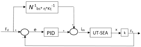
PID force controller used for closed-loop system. The end actuator is given name by the “UT-SEA” block.
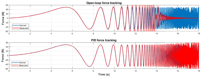
Chirp Signal Force control on UT-SEA Hardwaree using Arduino Mega 2560 Rev3.
The position control of the joint position is the second control goal to be met. The aim of position control is to track the fast changes in the intended joint positions precisely [5]. After properly attaining force control performance, the force controller may be utilised as a building block for the joint’s position control diagram. Figure 8 shows the kinematic structure of the UT-SEA overall structure where, L represents the linkage moment arm, c represents the distance between the actuator pivot and the arm pivot, b: distance between the arm pivot and pushrod pivot, F represents the actuator force, τ a the torque exerted on the output arm, θ a represents output arm angle, 𝜙 represents the offset angle.
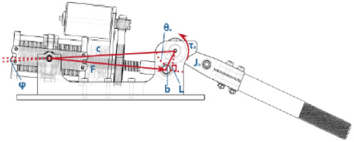
SEA CAD model kinematic structure of the arm mechanism. F: actuator force, τ a : torque exerted on the output arm, J a : inertia of the output arm, θ a : angle of the output arm, L: linkage moment arm, b: distance between arm pivot and pushrod pivot, c: distance between actuator pivot and arm pivot, 𝜙: offset angle.
SEA CAD model kinematic structure of the arm mechanism. F: actuator force, τ
a
: torque exerted on the output arm, Ja: inertia of the output arm, θ
a
: angle of the output arm, L: linkage moment arm, b: distance between arm pivot and pushrod pivot, c: distance between actuator pivot and arm pivot, 𝜙: offset angle [5]. However, we need to get this terms and know the equations to get every term. in Eq. (15) we have assumed b is equal to c to calculate length however this is not always the case
The torque (τ
a
) is calculated with respect to force output (F) of the actuator and clearly dependant also in length L which is in terms angle (θ
a
) which is illustrated in Eq. (16)
The dynamics relating τ
a
to with arm inertia (J
a
) and joint friction (B
a
)
Torque due to gravity and can be calculated knowing that (m
a
) is the mass of the load, (l
m
) is the distance between the load center of mass and the point of rotation. The offset angle (𝜙) is to correct (c) to prevent it from being orthogonal to the gravity vector.
Using Eq. (16) we deduce the following equation
Substituting by variables to have
Assuming no gravity to simplify the arm torque equation, the relation between (τ
a
) and (θ
a
) using Laplace Transform can be represented as the following:
By inverting Eq. (21), the desired arm torque (τ
ades
) given a desired arm angle (θ
ades
) can be written as:
However, the torque due to gravity (τ g ) must be summed with the desired arm torque (τ des ) signal to produce the desired motion. Then, multiplying the resulting torque by the inverse of linkage arm (L−1) to convert it into the desired force to be passed to the force controller the full picture is in Fig. 9.
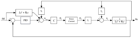
UT-SEA position controller.
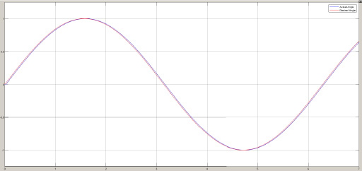
The second important performance metric on hardware for SEA is the position controller. The aim of the position controller is to precisely follow the desired angle with small overshoot, short settling time and low steady-state error. shows the Simulink model of the position controller. The actuator output shows that it can accurately track a reference signal that changes 60 degrees in a short time as in Fig. 10.
Position simulation on hardware.
One of the main advantages of SEAs is that they can safely share the same work space with humans. Unlike rigid actuators, SEA contains an elastic element added intentionally to improve the safety of the actuator. The actuator should be able to safely collaborate with humans while detecting impacts. Figure 11 shows the joint angle of SEA tracks the input signal and when the impact occurs at time between second 20 and second 25 (for example, a worker puts his hand in the arm path), the spring absorbs the shock while the controller get a large error in the spring force observed by an absolute encoder which indicates an impact so it sends a signal to make the arm move to the furthest possible location and this was simulated on MATLAB SIMULINK tool. We mainly used PID control in dynamic position control as it is a simple and effective control approach used for more than industrial control applications. It is also one of the most fundamental control method taught in control education. PID control can be realized by using a PLC which is a common controller selection in industry and can be implemented on cobots and they widely used in factories.
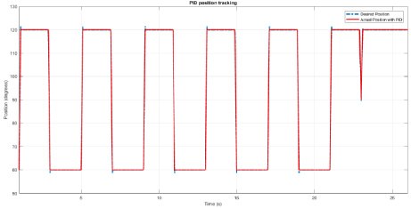
Position control simulation with dynamic obstacle interference.
During this research we have been keen to keep all factors fixed on reality same as modelling and simulating on software. We have been successful on this process however some factors could not be avoided. Firstly, the friction between hand rocker link and robotic arm head is increasing along the time of study due to its lifetime and entering of small dust particles in the clearance between two links although it was with minimal values due to placing UT-SEA hardware in lab but it cant be avoided. Also small deflections of aluminium material due to its low rigidity was experienced but it do not have any effect on movement of overall mechanism and this factor was considered when choosing aluminium alloy. Lastly, the shaft mounted with encoder experienced some resistance in motion but we solved this problem by making the clearance between shaft and the hole on steel base ±0.1 mm.
Conclusion
This paper introduced A new generation of industrial robots known as collaborative robots has been created and widely utilised in the automotive sectors to overcome the safety issues that arise when classic rigid actuators share the same work environment as people. Moreover, the challenge was to assemble the designed parts and and making motion analysis on CAD programs and analyzing the effects of motion elements on the assembly and make sure that the proposed SEA design is completely functional. Then, modeling the SEA accurately in order to achieve the two control objectives which are force and position control. A closed loop system with PID controller is used to obtain the desired response. The proposed force controller was able to track the given desired force. Also, the position controller used which includes the proposed force controller as the innermost block showed a good performance in tracking of the given desired angle. In other words, the results obtained from force control and position control were theoretically and practically successful on the hardware manipulator. Finally, SEA can be used to build a collaborative manipulator that can work side by side with humans to combine the benefits of both workers and robots. On the other hand, This model require high output power equipment, in terms of electric power output and mechanical manufacturing implemented on. Also, In order to detect any power difference and to apply compliance we require very high disturbance force this model dont work with very low forces so it can hurt if this point wont put in consideration.
List of symbols
Symbol
Description
Abbreviation
Description
T
Motor torque
SEA
Series elastic actutor
F
Output force
CAM
Computer aided manufacturing
Fb
eff
Force due to lumped damping
PID
Proportional-integral-derivative controller
F
m
Motor force
Cobots
Collaborative robots
F
o
Output force
FSEA
Force sensing series elastic actuator
F
u
Disturbance forces
RFSEA
Reaction force sensing series elastic actuator
l
Ball-screw lead
PWM
Pulse width modulation
N
Pulley ratio
HRI
Human to robot interaction
𝜂
Ball-screw mechanism’s efficiency
BLDC
Brushless DC motor
𝛽
Scaling factor
UT-SEA
University of Texas series elastic actuator
Φ
Offset angle
SA-SEA
Stoneage SEA
τ
Motor torque
T
ades
Desired arm torque
τ
a
Output arm torque
τ
g
Torque due to gravity
θ
des
Desired arm angle
N
bs
Actuator speed reduction
L
Linkage moment arm
m
a
Arm mass
m
k
Lumped sprung mass
m
o
Output mass
B
Joint friction
J
a
Output arm inertia
b
b
Viscous backdriving friction
b
eff
Lumped damping
b
k
Viscous spring friction