
Abstract
For compensating the gap of present investigations, which did not consider the effect of skin depth before, a novel method is also proposed to obtain the eddy current force. At the beginning, the separating principle of eddy current separator (ECS) is given. Then, based on boundary conditions and the eddy current equations, the internal magnetic flux density, eddy current density and eddy current force density of non-ferrous metal are deduced. By calculating the double integral of eddy current density, the internal eddy current of non-ferrous metal is achieved. The theoretical calculation method (TCM) for solving the eddy current force in the process of non-ferrous metal sorting is proposed. Moreover, to verify the correctness of TCM, taking 24-pole and 30-pole magnetic roller as examples, the finite element models of static and transient magnetic field are established respectively. Additionally, the correctness of TCM is proven by finite element method (FEM) when the x-axis and y-axis component of eddy current force is calculated. At the end, by the theoretical analysis and derivation derived in this paper, based on the relationship between the relative position of N and S poles of the magnetic roller and non-ferrous metal, the internal eddy current force are analyzed by the consistency between the direction of the internal magnetic flux density and the eddy current of non-ferrous metal. The influence of the size relationship between the non-ferrous metal and a single magnetic pole on the separation effect is discussed.
Keywords
Introduction
Since January 2021 the 364 tons of copper scraps were imported and increased by 73% year on year. It can be seen that China has a great demand for non-ferrous metal and the recovery capacity of non-ferrous metal needs to be improved. Additionally, ECS technology is an effective method for recovering and reusing non-ferrous metal, therefore the research on ECS has drawn great attention. At present, the permanent magnet drum eddy current separator (PMDECS) is widely used in the field of non-ferrous metal recovery because of its simple structure, green and environmental protection characteristics.
So far, researchers have done a lot of investigations on the prediction, simulation and experiment of separated material trajectory for ECS [1–5]. Due to the great throughput and demand of the ECS, improving its separation efficiency will produce huge economic return. As known, the separation ability can be elevated by increasing the separation angle of the ECS [6]. In [7], the two-step method was adopted, the conveyor belt structure was removed, two magnetic roller structures were used, then the low-cost scheme of ECS was given. However, compared with the traditional conveyor belt scheme with the single magnetic roller structure, the separation efficiency of the low-cost scheme was reduced. The separation efficiency of ECS depended on the eddy current force of non-ferrous metal, which could be reflected by the throwing distance of non-ferrous metal [8]. In [9], in order to investigate metal force in alternating magnetic field, the theoretical calculation method of average eddy current force on non-ferrous metal was completed. The analytical results were in good agreement with the experimental results. Jujun Ruan, who is a scholar, has accomplished the investigation on the mechanism of eddy current force of non-ferrous metal particles with different shapes in the alternating magnetic field of ECS, and the eddy current force analysis models of non-ferrous metal particles with different shapes are obtained [10]. In [11], the results showed that the tangential eddy current force had the greatest influence on the separation effect.
Researchers also tried to enhance the performance of ECS by improving the magnetic flux density, frequency and utilization rate of permanent magnet poles on the magnetic roller [12]. These schemes did advance the effect of separating non-ferrous metal to a certain extent. However, to enhance the separation effect of ECS, it is greatly significant to determine the key factors which affects the eddy current force in the process of non-ferrous metal being separated.
Although so many investigations have been conducted, at the moment there is still a lack of researches on ECS to report the magnetic flux density, eddy current density and eddy current force density of non-ferrous metal in the separation process. This paper systematically provides the calculation method and distribution law of these three key variable factors in non-ferrous metal in the eddy current separation process, which fills the theoretical vacancy of eddy current distribution inside the non-ferrous metal.
In [13], Ruan and Dong found the key factors of eddy current separation in metal aluminum. Researchers have done a large number of investigations on the theoretical calculation method and equivalent model of the magnetic flux density outside the magnetic roller [14–18]. The ECS can also be utilized in mining and metallurgy to separate precious metal [19]. In [20], Zhe Huang creatively analyzed the relationship between the block size of separating material and magnetic pole size of ECS from the perspective of the magnetic flux density, explained the influence of single magnetic pole size of magnetic roller on its separation particle range of ECS.
In previous investigations, researchers usually ignored the penetration depth of eddy current in non-ferrous metal. For instance, the scholar J. Ruan adopted the resistance unit to calculate the eddy current, thought that the eddy current was only distributed on the outer surface of non-ferrous metal, and exerted an integral of the current unit on the outer surface of metal blocks [10], which lacked an explanation and distribution law of the internal eddy current density analytical calculation method of non-ferrous metal.
For compensating the vacancy of present research, this investigation analyzes the separating principle of ECS from the perspective of eddy current force density, and proposes a new method to calculate eddy current force. Firstly, the separating principle of ECS technology is given. Secondly, to obtain the eddy current density in non-ferrous metal, taking the copper conductors with the size of 6–18 mm as an example, the calculation method of penetration depth is given, and in the l × h rectangular section of non-ferrous metal the phasor difference between each vertex of rectangular non-ferrous metal in polar coordinate is 𝜙 i . Then, the expression of magnetic flux density (see Appendix A) on the four edges of the non-ferrous metal section is obtained. Taking it as the boundary condition and adopting the eddy current equation of vector magnetic potential, the internal magnetic flux density and eddy current density of rectangular non-ferrous metal are deduced. The x-axis and y-axis components of the internal eddy current force density of l × h rectangular non-ferrous metal are calculated. The internal eddy current of non-ferrous metal is obtained by calculating the double integral of eddy current density. The TCM for solving the eddy current force in the process of non-ferrous metal sorting is proposed. Thirdly, to verify the correctness of TCM, taking 24-pole and 30-pole magnetic roller commonly used in engineering as examples, the finite element models of static and transient magnetic field are established respectively. Taking square and rectangular copper conductors as calculation models, the internal magnetic flux density, eddy current density and eddy current force density of non-ferrous metal are achieved through transient field, and the distribution law is given (position P 3, Appendix A, Fig. 17). Then, TCM and FEM algorithms are adopted to obtain the x-axis and y-axis components of eddy current force when the non-ferrous metal is directly located above the magnetic roller, which are consistent. Finally, by the internal eddy current force density method of non-ferrous metal derived from this research, based on the relationship between the relative position of N and S poles of the magnetic roller and the non-ferrous metal, the internal eddy current force is analyzed by the consistency between the direction of the internal magnetic flux density and the eddy current of non-ferrous metal. The influence of the size relationship between the non-ferrous metal and the single magnetic pole on the separation effect is discussed. Table 1 shows the variables used in this paper and their definitions, and the partial variable explanation is combined with Figs 1 and 17 (Appendix A).
Variable table
Variable table
Separating principle.
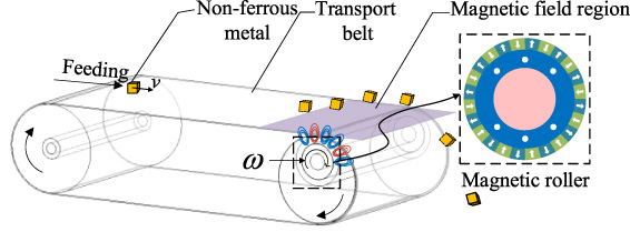
The magnetic roller of ECS (as shown in Fig. 1) is composed of a radial magnetized permanent magnet magnetic ring and a yoke. The magnetic poles are fixed on the yoke by screws, and the magnetization directions of the adjacent magnetic poles are opposite. The radial and tangential components of the magnetic flux density outside the magnetic roller can be decomposed to obtain multiple harmonic sinusoidal and cosinoidal waveforms by Fourier, and it only contains odd frequency harmonics. The frequency is determined by the number of magnetic poles k of the magnetic roller. In this investigation, the rotational speed of the magnetic roller is 3000 r/min, the frequency is 25nk Hz, and n is the number of harmonics, n = 1,3,5, etc.
As shown in Fig. 1, when the non-ferrous metal is placed on the conveyor belt of the ECS through the feeder, the non-ferrous metal moves at a uniform speed with the conveyor belt, gradually approaches the magnetic roller, and then enters the magnetic field area. According to the Lenz’s Law, radial and tangential repulsive force will be generated between the non-ferrous metal and the magnetic roller. The non-ferrous metal is endured with the horizontal and vertical eddy current force.
Non-ferrous metal is separated by horizontal throwing. And due to the internal eddy current distribution of the non-ferrous metal, the non-ferrous metal is separated by horizontal and vertical throwing movement as well. Because the eddy current distribution is quite uneven, it is difficult to make quantitative analysis. Therefore, it is generally considered that the eddy current is limited to distribute on the surface of non-ferrous metal.
Theoretical calculation methods of internal magnetic flux density, eddy current density, eddy current force density and eddy current force of non-ferrous metal
In order to explore the size and distribution law of the internal magnetic flux density, eddy current density, eddy current force density and eddy current force in non-ferrous metal, firstly, taking copper as an example, which is a non-ferrous metal with high separation demand, the calculation method of penetration depth of the metal is given. And then the boundary conditions (Appendix A) required for calculating the internal electromagnetic quantity of non-ferrous metal are given. From the aspect of eddy current density and eddy current force density by adopting the eddy current formula, the internal magnetic flux density, eddy current density, eddy current force density and eddy current force of non-ferrous metal are deduced. Compared with the FEM, the eddy current force theoretical calculation method through derivation in this research is called the TCM (see Section 3.4).
Penetration depth and material analysis
As the distribution of eddy current and electromagnetic wave in the conductor is affected by the skin effect, the depth of attenuation of magnetic flux density or eddy current density from the external surface to its e
−1 times is Δ. Therefore, before obtaining the eddy current force, the penetration depth Δ of the metal material at the corresponding magnetic field or eddy current frequency should be calculated, taking metal copper as an example, the penetration depth Δ under different magnetic flux density frequency is
Figure 2 shows the metal waste, in which the main particles to be separated are 6–18 mm non-ferrous metal (copper).
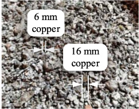
Metal waste.
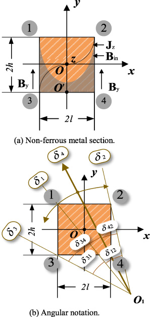
When the size of the non-ferrous metal is close to its penetration depth at the magnetic flux density frequency, the non-ferrous metal section is shown in Fig. 3(a). When there is only a y-axis component in the magnetic flux density, there is a distribution of magnetic flux density and eddy current density in the non-ferrous metal, and the magnetic flux density gradually attenuates from the outside to inside of the non-ferrous metal.
The magnetic flux density gradually decreases from the outside of non-ferrous metal to the inside, the internal eddy current density is on both sides of the y-axis with the same size and opposite direction, and only distributes from the region of the outer surface to the penetration depth. Fig. 3(b) shows the angular notation between the vertices of non-ferrous metal section. The non-ferrous metal section is rectangular, and its four vertices are recorded as point 1, point 2, point 3 and point 4 respectively.
Calculation model of non-ferrous metal.
According to Appendix A, the radial and tangential components of magnetic flux density of non-ferrous metal at the four edges can be expressed as
When the non-ferrous metal moves in the magnetic flux density, the magnetic flux density of points 1–4 is different due to the different distance from the magnetic roller. Under the polar coordinate system analysis, taking into (A.3) and (A.4), the radial and tangential component of the magnetic flux density outside the magnetic roller show sinusoidal and cosinoidal alteration along the circumferential angle. In Fig. 3(b) points 1–4 are located at different angles in polar coordinate, so phase compensation should be conducted when calculating the magnetic flux density amplitude outside the magnetic roller. The radial components of the magnetic flux density are
The tangential component general formula of magnetic flux density at point i is similar to (3), and it is cosinoidal form, i = 1–4. Take the position point 4 of r
4 as the reference point, and set its magnetic flux density phasor angle δ as zero, so
Then, the corresponding phasor angles δ1, δ2, δ3 of r
1, r
2 and r
3 are respectively
The eddy current formula is established and the non-ferrous metal is analyzed. Because the external magnetic flux density only contains x-axis and y-axis components which are also in alternating forms, the internal eddy current in the non-ferrous metal is a circulation among the z-axis direction. There are amplitude and phasor differences in the magnetic flux density on both sides of y-axis inside the non-ferrous metal, which is asymmetric with respect to the xOz plane. If position point 4 is set as the reference point, point 2 is in the opposite phasor direction to point 1 and 3 so as to simulate the phasor alteration of magnetic flux density on each boundary of non-ferrous metal. This alteration acts on the magnetic flux density itself, so
In the rectangular coordinate system, the eddy current formula of the internal vector magnetic potential is
Divide
Simplification of (8) can be obtained
The C
1, C
2, D
1 and D
2 are all determined by the boundary conditions, and they are written by
The internal eddy current density of the non-ferrous metal is
In combination with (10)–(12), the eddy current density can be solved as
The internal eddy current force density
θ is the angle between the eddy current density
The definite integral of the eddy current density solved by (13) is the eddy current of non-ferrous metal, and is expressed by
The current is the circulating current distributed in the yOz plane of non-ferrous metal, with the inward or outward direction perpendicular to the paper surface alternating with time. The concrete formula of eddy current with respect to time can be solved by bringing
On this basis, non-ferrous metal can be considered as charged conductor moving at a uniform speed in an alternating magnetic flux density with variable frequency and growing amplitude. Therefore, they are subjected to eddy current force
This section presents a new method for calculating the time-varying eddy current force on non-ferrous metal by using eddy current formula, which is called TCM throughout this paper. The distribution functions of the x-axis and y-axis components of the magnetic flux density inside the metal are shown in (10), the expression of eddy current density is shown in (13), the expression of eddy current force density is shown in (16), and the eddy current can be calculated by (19).
The purpose of this investigation is to calculate the eddy current force of non-ferrous metal in the process of eddy current separation, which is changing with time. Therefore, it is necessary to establish static magnetic field model and transient field model respectively to calculate the external magnetic flux density
Static magnetic field
The purpose of establishing the static magnetic field calculation model is to obtain the accurate magnetic flux density value outside the magnetic roller. The data of magnetic roller adopted in this paper are shown in Table 2. The FEM calculation model of the magnetic roller is established by Maxwell software. The solver is set as the static magnetic field solver and the natural boundary condition, Fig. 4 is the cloud map of magnetic flux density distribution in the cross section of the magnetic roller. When r = 0.148 m, the radial component and tangential component of the magnetic flux density above the 24-pole magnetic roller are 0.28 T and 0.32 T respectively.
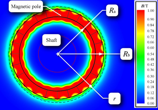
Magnetic flux density distribution of 24-pole magnetic roller (static magnetic field).
The FEM physical calculation model of transient magnetic field sets the data of the magnetic roller as the same as the static magnetic field simulation model. Band 1 is the rotational area of the magnetic roller, the rotation speed is 3000 r/min, the direction is clockwise, the conveyor belt area is rectangular. Band 2 is the moving area, the non-ferrous metal size is 6–18 mm, the linear speed v is 2 m/s, and the moving direction is horizontal right.
As displayed in Fig. 5, the magnetic flux density distribution of the FEM calculation is shown, and the local enlarged figure shows the magnetic flux density distribution inside the non-ferrous metal. The edge length of the non-ferrous metal is 6–18 mm, the fundamental frequency f 1 of the radial component of magnetic flux density generated by the magnetic roller is 600 Hz when the magnetic poles are 24, and the penetration depth of the corresponding conductor copper is 2.6 mm.

Magnetic flux density cloud map (magnetic roller and non-ferrous metal).
Non-ferrous metal calculation model (copper conductors).
Magnetic roller data
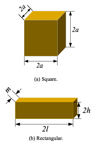
The non-ferrous metal (copper) calculation models are set as the square and rectangular copper blocks in Figs 6(a) and 6(b) respectively. The maximum eddy current force on them is calculated by TCM and FEM, whose biggest eddy current force is corresponding to position P 3, is also position directly above the magnetic roller. Combined with the results of finite element calculation of magnetic flux density outside the magnetic roller and the derivation results in Appendix A [((A.11))–((A.15))], from ((10)), ((11)), ((13)) and ((16)), when it is at position P 3, the x-axis and y-axis component calculated value of the internal eddy current force density and internal magnetic flux density of non-ferrous metal are shown in Fig. 7.
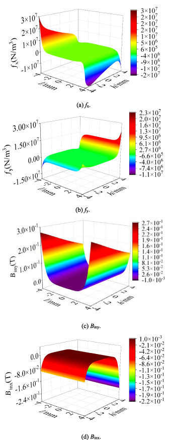
Internal force density and magnetic flux density distribution of non-ferrous metal at P 3 position.
Electric eddy current density distribution of non-ferrous metal section at position P 3.
As shown in Figs 7(a) and 7(b), the internal eddy current force density distribution of non-ferrous metal is asymmetric with respect to xOz plane and yOz plane. Combined with the non-ferrous metal section model in Fig. 17 (Appendix A), the eddy current force density f x on the side of the non-ferrous metal close to the magnetic roller (coordinates (4, −4)) is significantly greater than that away from the magnetic roller (coordinates (−4, 4)), which depends on the eddy current density J z and the y-axis component of the internal magnetic flux density B iny inside the non-ferrous metal. The distribution of the force density f y in the non-ferrous metal depends on the eddy current density J z and the x-axis component of the magnetic flux density B inx inside the non-ferrous metal.
Figures 7(c) and 7(d) are the y-axis component B iny and the x-axis component B inx calculated values of the internal magnetic flux density of non-ferrous metal respectively by (10). As shown in Fig. 7(c), the y-axis component of the magnetic flux density is distributed inside the non-ferrous metal. At this time, the position where the x-axis coordinate takes 0 has no magnetic flux density distribution due to the skin effect.
Since the bottom boundary is close to the magnetic roller, the magnetic flux density amplitude is obviously higher up to 0.28 T. Besides, the magnetic flux density amplitude gradually decreases with the increasing y-axis and the minimum is 0.14 T. Figure 7(d) shows that the x-axis component B inx of magnetic flux density at the bottom edge of non-ferrous metal is close to 0, which is caused by the phasor difference [shown as Figs 3(b) and (6)]. However, the position where the y-axis coordinate takes 0 has no magnetic flux density distribution due to the skin effect.
In order to verify the correctness of the results obtained in Section 3.4, the magnitude and distribution of electric eddy density obtained by FEM and theoretical derivation are compared and analyzed. Additionally, the eddy current force calculated by TCM and FEM under 24-pole and 30-pole magnetic roller is compared and investigated.
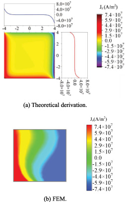
Electric eddy current density
When the non-ferrous metal copper with the size of 8 mm × 8 mm × 8 mm is close to the direct top of the magnetic roller (position P 3 in Fig. 17, Appendix A), the electric eddy current density distribution of non-ferrous metal by theoretical derivation and FEM. As shown in Figs 8(a) and 8(b), the distribution value and trend law of these two methods are similar, which verifies the correctness of the eddy current density calculation by theoretical derivation in Section 3.2.
Eddy current force
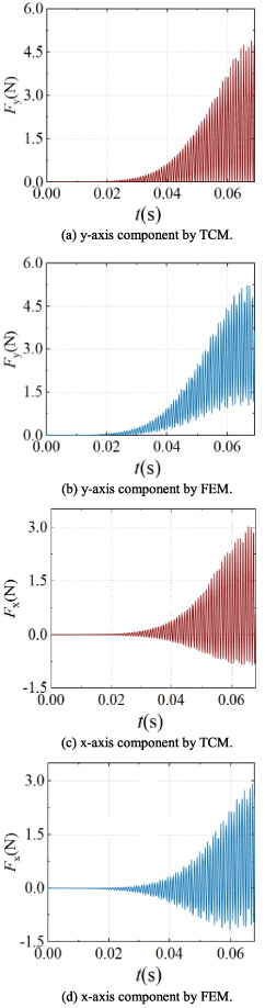
Through TCM and FEM calculation, assuming l = 4 mm, h = 4 mm and m = 8 mm, the TCM and FEM calculation results of the eddy current force on non-ferrous metal (copper) in the separation process (P
1–P
3, Fig. 17, Appendix A) are obtained, as shown in Figs 9(a)–9(d). As shown in Figs 9(a) and 9(b), the eddy current force waveforms calculated by FEM and TCM are very similar. By comparing and analyzing Figs 9(a) and 9(b) there are certain gaps between TCM and FEM in the minimum value after 0.03 s. According to ((20)), the eddy current force
When the eddy current force is calculated by the TCM, the magnetic flux density of the four edges of the non-ferrous metal is used for the calculation. The magnetic flux density presents the form of amplitude variation and frequency fluctuation along the edges of non-ferrous metal, and they are all oriented along the x-axis. The mean value of the multipoint magnetic flux density around the non-ferrous metal is taken in (20). When the position of the non-ferrous metal is oblique above a pair of magnetic poles with opposite polarity, theoretically, the superposition sum of the magnetic flux of the non-ferrous metal is not 0. However, the x-axis component of the magnetic flux density calculated by TCM at the edge of non-ferrous metal may be a number close to 0, which leads to the errors between Figs 9(a) and 9(b). The maximum amplitude of the eddy current force in the y-axis component has been used to judge that non-ferrous metal can be reliably separated and thrown out. The minimum value of eddy current force in the y-axis direction will not significantly affect the separation efficiency of non-ferrous metal.
Eddy current force of non-ferrous metal moving (P 1–P 3).
Relative errors of eddy current force by TCM and FEM for square copper conductors (24-pole roller)
Because the y-axis component of eddy current force is much greater than the gravity of the copper conductor, the copper conductors will be thrown out before position P 3. After the metal leaves the conveyor belt, the magnetic flux density surrounding the non-ferrous metal decreases rapidly. In order to facilitate the quantification error, the TCM and the FEM in this research both utilize the eddy current force of the copper conductor at position P 3. Taking the copper block shown in Fig. 6(a) as the calculation model, setting the edge length of square copper conductor with different sizes, the magnetic flux density of 24-pole magnetic roller is obtained. The eddy current force generated by 24-pole magnetic roller is calculated by TCM and FEM are shown in Fig. 10.
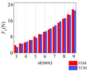
Eddy current force by TCM and FEM for square copper conductors (24-pole roller).
Eddy current force of non-ferrous metal at different position.
Eddy current force by TCM and FEM for rectangular copper conductors (24-pole roller).
Eddy current force by TCM and FEM for square copper conductors (30-pole roller).
Eddy current force by TCM and FEM for rectangular copper conductors (30-pole roller).
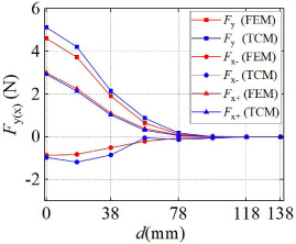
To verify the accuracy of TCM, taking the non-ferrous metal in Fig. 17 as the analysis object. After the non-ferrous metal enters the magnetic field, the distance between the non-ferrous metal and the perpendicular line of the magnetic roller center is marked as d. The FEM and TCM are used to calculate the amplitude of eddy current force of each position on the conveyor belt. As shown in Fig. 11, assuming l = 4 mm, h = 4 mm and m = 8 mm, the results of the two methods are consistent in multiple points above the magnetic roller.
The relative error and average absolute error of the calculation results of different sizes are viewed in Table 3. The errors between TCM and FEM are very small. Except for a = 3 mm, the corresponding calculation error of other size metal is less than 10%. At this time, the upper edge of the non-ferrous metal are very close to the magnetic roller, and the y-axis component of eddy current force
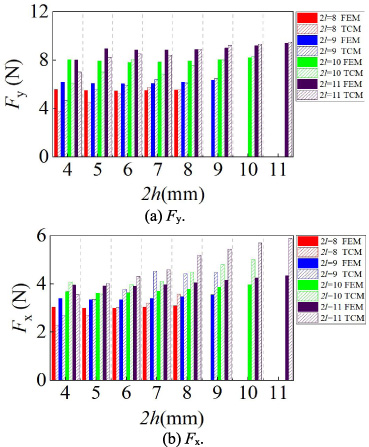
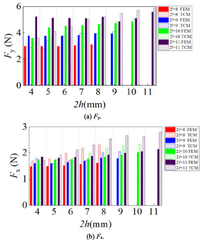
Taking Fig. 6(b) as the eddy current force calculation model of copper conductors, set the rectangular copper non-ferrous metal with different thickness h and different length l, and the axial length m is consistent with the length l. The TCM and FEM calculation results of eddy current force F y and F x are shown in Figs 12(a) and 12(b) respectively. They list the maximum value of eddy current force on copper conductors of different sizes in alternating magnetic flux density (non-ferrous metal is at position P 3, Fig. 17, Appendix A). Additionally, the x-axis is the length 2h of non-ferrous metal along the y-axis, and the y-axis is the eddy current force. Moreover, different x-axis size 2l are marked by different colors, the solid colors represent FEM calculation results, and the gradient fills represent TCM calculation results.
Relative errors of eddy current force by TCM and FEM for square copper conductors (30-pole roller)
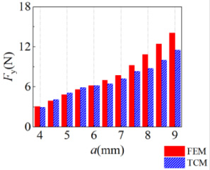
In order to verify the applicability of the TCM, this investigation also compares and analyzes the results of eddy current force of the 30-pole magnetic roller by TCM and FEM. Taking Fig. 6-a as the calculation model, setting the edge length of square copper conductors with different sizes, the TCM and FEM calculation results are shown in Fig. 13 and Table 4 respectively.
By comparing and analyzing Tables 3 and 4, when TCM is used to calculate eddy current force on large size non-ferrous metal (a ≥ 8 mm), the calculation error of eddy current force generated by 30-pole magnetic roller is much bigger than that of 24-pole magnetic roller.
Compared with the 24-pole magnetic roller, the volume of the single magnetic pole of the 30-pole magnetic roller is much smaller. Each two magnetic poles form a closed magnetic circuit with the external air gap. The internal magneto-motive force formed by the smaller magnetic pole is significantly smaller than that of the 24-pole magnetic roller, so the external magnetic flux density decays faster. Unlike air, copper is a great conductor of magnetic field. The influence of non-ferrous metal copper on the magnetic flux density of the upper edge
Different from 24-pole magnetic roller, 30-pole magnetic roller has smaller single magnetic pole size. The magnetic flux direction at the top of large non-ferrous metal may change twice, so the errors of calculating eddy current force using the magnetic flux density average value at the top edge of non-ferrous metal become more obvious. The vector superposition of the magnetic flux of each element in the non-ferrous metal can be calculated by using the FEM. Due to the large size of a single magnetic pole, the 24-pole magnetic roller is not affected by this factor.
According to Table 4, the calculation results of the TCM for copper conductors below 16 mm are more accurate, and the maximum error is confined to 10.04%. For 16–18 mm copper conductors, the maximum error is 19.47%. The average error of the TCM for calculating the y-axis component of eddy current force of square conductor is 9.27%. The correctness of the method is verified. For rectangular copper conductors of different sizes, the TCM calculation results and FEM calculation results of eddy current force F y and F x are shown in Figs 14(a) and 14(b) respectively.
Relative size of non-ferrous metal and magnetic pole.
In this investigation, the eddy current force density
Distribution of magnetic flux density and eddy current force density in non-ferrous metal at P u .
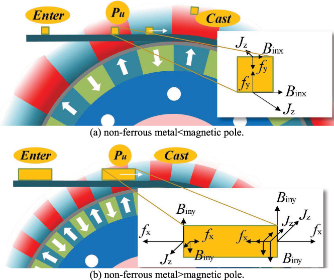
Figures 15(a) and 15(b) are schematic diagrams of non-ferrous metal with different sizes and magnetic poles with different number of poles. The internal eddy current force density of non-ferrous metal depends on its internal magnetic flux density and eddy current density. While the magnetic roller rotates at a high speed, as the non-ferrous metal gradually approaches the magnetic roller, the magnetic flux density inside the non-ferrous metal alters in value and direction. From (19), since the magnetic flux density on both sides of non-ferrous metal is regularly alternation (I z ≠ 0), there is always eddy current in the non-ferrous metal, and the eddy current density on both sides of x-axis or y-axis are opposite. Only if the non-ferrous metal is directly above the center of the magnetic roller, the magnetic flux density on both sides of non-ferrous metal is equal.
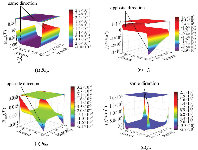
The coordinate range inside the non-ferrous metal is x = [−l, l] and y = [−h, h], as shown in Figs 16(a) and 16(b). Combined with the non-ferrous metal section model in Fig. 17, when the non-ferrous metal is at P u , the y-axis component of magnetic flux density of non-ferrous metal on xOz plane is all in the same direction. This is consistent with the calculation of internal magnetic flux density of non-ferrous metal by transient magnetic field FEM calculation in Section 4.2.
From (14),
As shown in Fig. 16(a), the magnetic flux density B iny on both sides of the y-axis is in the same direction. The direction of eddy current density J z is opposite on both sides of the y-axis of non-ferrous metal. The calculation result of x-axis component f x of eddy current force density is shown in Fig. 16(c), and f x is opposite on both sides of the y-axis. For the internal eddy current force density of the whole non-ferrous metal, the volume integral is taken, and the eddy current force density on both sides of the y-axis is neutralized by the symmetrical position.
The above laws still apply to the x-axis component of magnetic flux density. As shown in Fig. 16(b), the magnetic flux density B inx on both sides of y-axis is in the opposite direction, and the electric density direction is also opposite. Therefore, the calculation results of the y-axis component eddy current force density f y are in the same direction on both sides of the y-axis, as shown in Fig. 16(d). For the internal eddy current force density of the whole non-ferrous metal, the volume integral is taken, and the eddy current force density on both sides of the y-axis is the superposition relationship.
The magnetic flux density distribution of the magnetic roller is determined by the size of the magnetic pole. According to (A.3) and (A.4), the difference between the radial component and the tangential component of the magnetic flux density outside the ECS is 90° electrical angle.
At the symmetrical axis of a single magnetic pole, the radial component of the magnetic flux density reaches the maximum, and the tangential component of magnetic flux density is 0. At the junction of two magnetic poles with different magnetization directions, the tangential component of the external magnetic flux density reaches the maximum, whereas the radial component of the external magnetic flux density is close to 0.
Under the case, the size of the magnetic pole angle is too large and the size of non-ferrous metal is too small. Firstly, from (19), the eddy current density is related to the magnetic flux density difference on both sides of the non-ferrous metal. When the non-ferrous metal is small, the magnetic flux density amplitude and phasor difference on both sides of the non-ferrous metal are small, so the eddy current density is small. Secondly, the non-ferrous metal can not be obtained by horizontal repulsion and vertical repulsion at the same time, so it is difficult to be separated.
If the size of the magnetic pole is too small compared with the cross-sectional area of non-ferrous metal is shown as P u in Fig. 15(b), the y-axis component of magnetic flux density of non-ferrous metal in xOz plane alternates between positive value and negative value. Therefore, the eddy current force density on both sides of y-axis alternates between positive value and negative value. When solving the integral, the eddy current force density is still the offset relationship, weakening the separating efficiency of the ECS.
Therefore, the separation effect of the ECS is affected by the relationship between the size of the non-ferrous metal to be separated and the size of the single magnetic pole of the magnetic roller. When the cross-section size of the non-ferrous metal is close to the cross-section size of the single magnetic pole of the magnetic roller, the separation effect is better than that when the single size of the magnetic pole is too large or too small.
In this paper, considering the skin effect of non-ferrous metal, a new method for the eddy current force is proposed. The finite element models of 24-pole and 30-pole magnetic roller of of static and transient magnetic field are established respectively. A great number of good results are achieved as: The calculation method and distribution laws of internal magnetic flux density, eddy current density and eddy current force density in non-ferrous metal separating are deduced. The calculation results are consistent with the finite element calculation results. In the view of 24-pole magnetic roller, the errors between TCM and FEM are small. Except for a = 3 mm, the corresponding calculation error of other size metal is less than 10%. The average error between the TCM and the FEM to calculate the y-axis component of eddy current force on square conductor is only 5.01%, which fully prove the correctness of TCM. In the view of 30-pole magnetic roller, the calculation results of the TCM for copper conductors below 16 mm are more accurate, and the maximum error is confined to 10.04%. For 16–18 mm copper conductors, the maximum error is 19.47%. The average error of the TCM for calculating the y-axis component of eddy current force of square conductor is 9.27%. The separation effect of the ECS is affected by the relationship between the size of the non-ferrous metal to be separated and the size of the single magnetic pole of the magnetic roller. When the cross-section size of the non-ferrous metal is close to the cross-section size of the single magnetic pole of the magnetic roller, the separation effect is better than that when the single size of the magnetic pole is too large or too small.
Footnotes
Acknowledgements
This work is supported by
1. Postdoctoral Research Launch Fund from Heilongjiang Province (2023BSH05): Investigation of Doubly-fed Brushless Motor Power Generation and Electric State.
2. 2021 Basic Research Funding Project in Heilongjiang Province (2021-KYYWF-1467): Study on Subsynchronous/Hypersynchronous Oscillation of Multi-terminal DC Transmission System for New Energy.
3. 2020 Basic Research Funding Project in Heilongjiang Province (2020-KYYWF-0700): Investigation of Stress Mechanisms optimization Design Methods for Dynamic Load Constrained Variable and Frequency Permanent Magnet Synchronous Motor in Heavy Scraper Machines.
Appendix A.
According to the finite element calculation, the radial component
From (A.1) and (A.2), the radial component and tangential component expression of the magnetic flux density outside the magnetic roller of the ECS with radius variable r in polar axis and time variable t are
In Fig. 17, the non-ferrous metal section has been partially enlarged. There are two coordinate systems in Fig. 17, namely, the magnetic roller displayed by the polar coordinate system and the non-ferrous metal displayed by the rectangular coordinate system. Assuming that the non-ferrous metal will not be thrown out all along, it will move from the left position P 1 on the conveyor belt to the position P 3 through the position P 2.
Set t = 0 when the non-ferrous metal is at position P
1. In Fig. 17, the motion model contains two coordinate systems, and the magnetic flux density frequency of the magnetic roller around the moving non-ferrous metal is jointly determined by the number of magnetic poles of the magnetic roller, the rotation speed of the magnetic roller and the horizontal movement speed of the non-ferrous metal. r
12 is the radius coordinate from vertex 1 to vertex 2 of non-ferrous metal section, so
If the polar coordinate angle of the initial position is 𝛼0, see Fig. 17, 𝛼 with the variable t can be expressed as
Substituting (A.5), (A.9) and (A.10) into (A.3) and (A.4) respectively, the radial and tangential component expressions of the magnetic flux density at the non-ferrous metal position are
The expressions of B
ri
for the magnetic flux density boundary conditions of non-ferrous metal can be shown as the following, and the tangential component B
ti
is the cosine form of the radial component B
ri
.
Appendix B.
The prototype provided by the supplier is asymmetric magnetic roller with 18 poles. Half of the magnetic pole-pairs with the angle of 30° and the other half with the angle of 60°. The inner and outer radius of the magnetic roller and the operating speed are consistent with the Table 2. The magnetic roller for the prototype assembly is shown in Fig. 18. The experimental photographs are shown in Fig. 19.
According to the experimental measurement, the radial component of magnetic induction density is 0.3633T at 10 mm from the magnetic pole surface with a magnetic pole-pair angle of 60°. After establishing the model according to the experimental prototype, as shown in Fig. 20. The radial component of the magnetic flux density amplitude at the same position is 0.3560T, and the relative error with the field measurement result is only 2.01%, which fully verifies the correctness of the FEM model.