
Abstract
Dual field generation layer (FGL) spin torque oscillators (STO) were investigated for use in microwave-assisted magnetic recording. The STOs were integrated into the gaps of write heads for stable oscillation. According to preliminary calculations, a FGL thickness of 5 nm was suitable, while the volume of 7.5 nm and 10 nm thick FGLs was too large and they did not oscillate stably. The most dominant factor influencing the FGL rotation was found to be the strength of the antiferromagnetic coupling between the FGLs. Other parameters were also varied, e.g., the exchange coupling between the negative spin injection layer (nSIL) and the trailing shield (TS), however, no significant effect was found. Unlike single FGL STOs, the oscillation frequency changed drastically, from 38 GHz to 73 GHz, on varying the injected current density to the STO. Recording simulations showed that the signal-to-noise ratio was maximized for an STO oscillation frequencies between 34 GHz and 50 GHz, depending on the recording media used in the calculations. Therefore, the dual FGL STO may be suitable for a wide range of recording media. Alternatively, the dual FGL STO may be used for dual-layer recording, where different resonance frequencies are needed for each of the layers, obviating the need for a second STO.
Keywords
Introduction
Conventional perpendicular magnetic recording (PMR) is reaching its areal recording density limit as recording medium grains cannot be made any smaller due to the requirement that the media magnetization be thermally stable. Next-generation recording methods have been proposed and studied as a way to solve the so-called trilemma issue and increase the recording density significantly. Microwave-assisted magnetic recording (MAMR) [1,2] is one of the candidates for next-generation magnetic recording technology. In MAMR, the high-frequency magnetic field, generated by a spin-torque oscillator (STO), is superimposed on the magnetic head field and induces ferromagnetic resonance in the recording medium, making it possible to record on a high-coercivity medium. Therefore, the spin-torque oscillator is the most important component in a MAMR system. Although MAMR-related technology has been realized in commercial hard disk drives [3], we have yet to see microwave-assisted switching (MAS) implemented in products. One of the issues to solve is stable STO oscillation [4]. Recently, the dual field generation layer (FGL) STO, with two field generation layers, has been proposed [5–7]. It has superior characteristics when compared with conventional STOs containing a single FGL, such as higher SNR of written tracks due to the zero STO perpendicular field component, which is harmful to recording, at the position where the in-plane component of the STO field peaks.
In this paper, first, a dual FGL STO integrated into the gap of a write head was investigated for stable STO oscillation. Next, medium recording simulations were performed to validate the stable STO oscillation. The results showed that the exchange coupling between the nSIL and the trailing shield (TS) had little effect on the oscillation of the two FGLs, while antiferromagnetic coupling between the FGLs allowed the FGLs to oscillate stably, yielding a very high oscillation frequency. The FGL thickness was another important factor. Media simulations showed that the SNR increased when a dual FGL/single SIL STO was employed compared recording without a STO, i.e. PMR.
Calculation model
As shown in Fig. 1, the STO was inserted into the gap between the main pole (MP) and the TS of the write head. The dual FGL STO was composed of two FGLs and one spin injection layer with negative polarization (nSIL). The dimensions of each FGL were 40 nm × 40 nm × 5 nm. Note that we have not been able to obtain stable FGL magnetization rotation in a single FGL STO of this size. The STO was tilted by 25° towards the trailing shield with respect to the normal to the air-bearing surface (ABS). The MP–TS gap was 18.8 nm at the ABS. An injected current flowing through the STO from the MP to the TS was assumed, spin transfer torque (STT) between FGL1 and the MP, and FGL2 and the nSIL, was assumed, while there was no STT between FGL1 and FGL2. Antiferromagnetic coupling, Jex, was assumed between FGL1 and FGL2. To solve the LLG equation ((1)) with a STT term ((2)) [8 ], we used the FastMag Micromagnetic Simulator (Numerics and Design, Inc.) [9 ].

Schematic of (left) write head and (right) inserted dual FGL STO used for the calculations [5].
The whole space including the write head, STO, and soft magnetic underlayer (SUL) was treated micromagnetically and was divided into tetrahedral elements. The edge lengths of the STO and main pole (MP) tip region were less than 2 nm and below 30 nm in the remaining region. The total number of tetrahedral elements of the whole model was typically 3–4 million, which was the upper limit of our system (GPU: GeForce RTX 3090, CPU: Intel Core i9-9900K) primarily due to GPU memory constraints.
Prior to the main calculation, we performed a degauss of the write head without the STO for 100 ns, followed by the main calculation with the STO for 8–16 ns. The time integration of the degauss and main calculation, Δt, was 10 ps and 0.01 ps, respectively. The calculation time was typically 24 hours for an 8 ns simulation on the RTX-3090.
Tables 1 and 2 show, respectively, the main parameters of the recording head and the STO. These were the default parameters, unless noted otherwise. The thicknesses of the two FGL layers were both 5 nm (see Section 3.1). Note that the FGL magnetization did not rotate stably in the FGL plane due to the large volume for the 7.5 nm and 10 nm thick FGLs. Figure 2 shows a schematic diagram of the recording head and recording medium. The recording medium was 4 nm thick and consisted of a 2 nm hard layer and a 2 nm soft layer. The distance from the ABS to the soft magnetic underlayer (SUL) surface was 18 nm, and the surface of the recording layer was 3.5 nm from the ABS.

Schematic of (left) write head and (right) recording layers used for the calculations.
Main parameters of the write head, SUL and medium used for the calculations
Main parameters of the FGL and SIL used for the STO simulations
Effect of exchange coupling between layers on STO oscillation
First, the exchange coupling between each layer of the STO was varied. To determine the proper thickness of the FGL, preliminary verification was performed using models with FGL layer thicknesses of 5 nm, 7.5 nm, and 10 nm. In the 5 nm FGL model, the STO oscillated relatively stably, but in the 7.5 nm and 10 nm FGL models, the volume was too large for the magnetization to rotate coherently. Therefore, in this paper, the thicknesses of the two FGLs were assumed to be 5 nm.
Next, the exchange coupling between the nSIL and the TS was examined. The exchange coupling was varied from the initial value of 12.5 erg/cm2 [5] to 0.0 erg/cm2, 6.25 erg/cm2, and 25.0 erg/cm2. Figures 3(b) and 3(c) show the STO oscillation (two FGLs and the nSIL) for nSIL–TS exchange of 0.0 erg/cm2 and 25.0 erg/cm2, respectively. The reference result, using the values in Tables 1 and 2 is shown in Fig. 3(a). The exchange coupling between nSIL and TS had the effect of controlling the in-plane rotation of nSIL. Making the nSIL–TS exchange equal to zero led to a large in-plane nSIL oscillation; the in-plane oscillation was suppressed and the oscillation occurred out of the plane when the coupling was increased to 6.25 erg/cm2. When the coupling was varied over the range from 6.25 erg/cm2 to 25.0 erg/cm2 no notable differences in the nSIL rotation were observed. With regard to the FGL1 and FGL2 rotation, the exchange coupling between the nSIL and the TS had only a small effect; i.e. the effect of improving FGL1 and FGL2 oscillation was not obtained.

Volume-averaged STO oscillation vs. time for various nSIL–TS exchange coupling strengths. (Top) FGL1, (middle) FGL2, and (bottom) SIL. FGL1–FGL2 exchange = −1.33 erg/cm2, J = 4.0 × 10⁸ A/cm2.
Next, the exchange coupling between FGL1 and FGL2 was considered. The default antiferromagnetic coupling between FGL1 and FGL2 was −1.33 erg/cm2 [5]. Here we focus on the magnetic interaction between the two FGLs and discuss the improvement due to the exchange coupling. Figure 4 shows the volume-averaged STO oscillation vs. time for FGL1–FGL2 exchange = −10 erg/cm2. When the FGL1–FGL2 exchange was −10 erg/cm2, the oscillation amplitude became large and the oscillation frequency was very high (72 GHz) and may not be appropriate for typical recording media. In Fig. 5, the oscillation frequency vs. injected current density to STO is shown. Unlike the single FGL STOs, the oscillation frequency changed drastically, from 38 GHz to 73 GHz, by varying the injected current density to the STO. It is seen that the STO oscillation frequency varied between 33 GHz and 42 GHz over the current density range from J = 2.5 × 10⁸ to 3.5 × 10⁸ A/cm2. This was followed by an abrupt frequency change between J = 3.5 × 10⁸ and 4.0 × 10⁸ A/cm2, after which the oscillation frequency was around 70 GHz–80 GHz when J was between 4.0 × 10⁸ and 5.5 × 10⁸ A/cm2.

Volume-averaged STO oscillation vs. time. (Top) FGL1, (middle) FGL2, and (bottom) SIL. FGL1–FGL2 exchange = −10 erg/cm2, J = 4.0 × 10⁸ A/cm2.

Primary resonance frequency of STO vs. injected current density (J). FGL1–FGL2 exchange = −10 erg/cm2.
This results means that we can use the same STO to apply two different frequencies to the medium by varying the injected current density to the STO. Volume-averaged STO oscillations vs. time and Fourier transforms of the oscillations are shown in Fig. 6 for various injected current densities to the STO. At J = 2.5 × 10⁸ A/cm2 a single, low frequency peak was observed in the FFT of the STO oscillation. When J was increased to 3.5 × 10⁸ A/cm2, a primary peak at 39 GHz and a small, secondary peak emerged at 60 GHz. When J reached 4.5 × 10⁸ A/cm2, a single peak was found at 73 GHz. Note that similar tendencies were observed for write heads with various Hk values. In a single FGL STO, stable STO oscillation is generally obtained when the spin torque field generated by the injected current and the applied field are balanced and the window in which this occurs is fairly narrow: stable STO oscillation is not obtained for low J, while chaotic oscillation occurs for excessively large J. The phenomenon of multiple stable oscillation frequencies discussed here has not been previously reported.

Volume-averaged STO oscillation and Fourier transform of oscillation vs. time for various injected current density (J) to STO. (Top) J = 2.5 × 10⁸ A/cm2, (middle) 3.5 × 10⁸ A/cm2, and (bottom) 4.5 × 10⁸ A/cm2. FGL1–FGL2 exchange = −10 erg/cm2.
Figure 7 shows a schematic diagram of a single FGL/single SIL STO [3], where the SIL had a positive polarization. The gap and STO were inclined at 15° with respect to the normal to the recording layer and the MP–TS gap was 20 nm. Figure 8 shows the calculated results for this STO. Here, transmission spin torque was assumed and the dimensions of the FGL were 20 nm × 20 nm × 10 nm, which was half the volume of each FGL in the dual FGL/single SIL STO. Despite the smaller FGL volume, a higher injected current density of J = 7.0 × 10⁸ A/cm2 was required for stable oscillation. In spite of this, the in-plane FGL magnetization amplitude and oscillation frequency were smaller (26 GHz). Therefore, it was shown that the dual FGL/single SIL STO could achieve a higher oscillation frequency and stable oscillation at a lower injection current density than the conventional single FGL/single SIL STO.

Schematic of write head gap vicinity and arrangement of single FGL/single SIL STO.

Volume-averaged single FGL/single SIL STO oscillation vs. time. J = 7.0 × 10⁸ A/cm2.
In this section, recording simulations were carried out using a write head field distribution and the field from the dual FGL/single SIL STO.Note that an in-house micromagnetic simulator was used to solve the LLG equation (1), and an analytical STO model was used which did not require the STT term in (2). The recording layer properties were based on those in [10] and should be suitable for use with STOs which oscillate at high frequencies. The granular recording layer consisted of grains with an average size of 8 nm and an average pitch of 9 nm. Each grain was composed of a 2 nm thick hard layer and a 2 nm thick soft layer, with saturation magnetization, Ms, of 750 emu/cm3. The uniaxial anisotropy, Ku, of the hard layer was varied and the soft layer Ku was 10% of the hard layer Ku.
Figure 9 shows the time variation of the total write head magnetic field and STO magnetic field used in this study. The small fluctuations in the write head field are due to the superposition of the STO magnetic field. In the recording simulations the head field distribution at 3.2 ns, i.e. the saturated state, was used and scaled to reflect the finite rise and fall times.

Write head field with superimposed STO field (recording field) vs. time.
Figure 10 shows the signal to noise ratio (SNR) as a function of hard layer Ku, calculated with and without the STO, where each data point represents the average value of twenty tracks and the error bars show the standard deviation of the SNR. The SNR was calculated from readback waveforms obtained using the sensitivity function of a 40 nm wide magnetoresistive read head with a gap length of 20 nm. The written tracks had a bit length of 25 nm and the write head velocity was 10 m/s.

SNR vs. K u hard obtained by media recording simulations. SNR gain by STO was around 18 dB at K u hard = 26 × 106 erg/cm3, while less than 3 dB at K u hard = 34 × 106 erg/cm3.
For hard layer Ku from 26 × 106 erg/cm3 to 34 × 106 erg/cm3, higher SNR was obtained when using the dual FGL/single SIL STO. Figures 11–13 shows the SNR for each of three hard layer Ku values when the FGL oscillation frequency was varied. The maximum SNR was obtained at STO oscillation frequencies of 34 GHz for Ku = 26 × 106 erg/cm3, 40 GHz for Ku = 30 × 106 erg/cm3, and 50 GHz for Ku = 34 × 106 erg/cm3. The STO had a big effect on the SNR when Ku hard was low (26 × 106 erg/cm3), while for the highest Ku (34 × 106 erg/cm3), the performance was poor, but still better than using no STO.
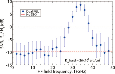
SNR vs. high-frequency (HF) field frequency, K u hard = 26 × 106 erg/cm3. SNR gain by STO was around 18 dB at the highest SNR.
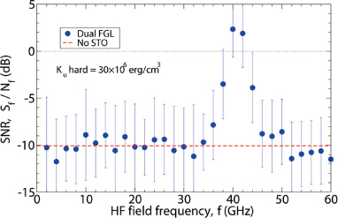
SNR vs. HF field frequency, K u hard = 30 × 106 erg/cm3. SNR gain by STO was around 12 dB at the highest SNR.
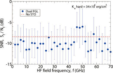
SNR vs. HF field frequency, K u hard = 34 × 106 erg/cm3. SNR gain by STO was less than 3 dB at the highest SNR.
We investigated how to obtain stable oscillation of dual FGL/single SIL STOs integrated into a write head. First, the exchange coupling between the layers of the STO was investigated in order to obtain more stable oscillation. It was found that introducing antiferromagnetic exchange coupling between the two FGLs was effective. In particular, a value of −10 erg/cm2 was optimal. Unlike the conventional single FGL/single SIL STO, the oscillation frequency changed drastically, from 38 GHz to 73 GHz, on varying the injected current density to the STO. Because we can control the oscillation frequency by varying the injected current density, the dual FGL/single SIL STO can be easily applied to dual-layer recording, where two different oscillation frequencies must be used [11]. This would be a big benefit in terms of reducing the cost and complexity of dual-layer recording systems, which would otherwise require two, separate STOs.
Although genuine microwave-assisted magnetic recording (MAS-MAMR) drives have not yet reached the market, several MAMR-related technologies have been derived and commercialized as noted earlier [3,12]. In the near future, dual FGL/single SIL STOs may enable the realization of MAS-MAMR drives, whilst dual-layer recording with the dual FGL STO would substantially increase the areal recording density.
Due to the lengthy simulations required, the available data could be affected by uncertainty and/or some degree of inaccuracy. In such a case a fuzzy processor approach might be used to help determine the optimal STO parameters [13]. This will be investigated in future work.
Footnotes
Acknowledgements
The authors acknowledge financial support from the Advanced Storage Research Consortium (ASRC) and software support from JSOL, Japan.