



Abstract
Traditional scroll compressors are difficult to achieve oil-free operation due to the presence of a high-friction anti-rotation mechanism. This paper proposes a magnetic drive oil-free scroll compressor to solve this problem. Firstly, the structure and principle of this scroll compressor are introduced. Then the finite element analysis of the electromagnetic system was conducted; the dynamics model of the magnetic scroll compressor operating in the uncompressed state was established. Finally, the PID control of the system is performed, and simulations and experiments are carried out. Experimental results: under the 0.05 mm step signal in the X direction, the position response time of the system is 0.1 s, and the angle response time of 0.001 rad is 0.2 s. The results show that the oil-free scroll compressor has good position control response characteristics.
Introduction
The scroll compressor has the characteristics of stable operation, energy saving, and low noise. It is widely used in production. With the increasing attention to the environment, oil-free scroll compressor has gradually become the focus of the compressor industry [1,2]. At present, the research on oil-free scroll compressor is generally to change the oil-lubricated bearing into a self-lubricating bearing, or to apply self-lubrication on the anti-rotation device [3]. In order to reduce friction, H Li proposed to use self-lubricating materials for sealing elements by analyzing the working process of scroll compressor; Multiple crankshafts are used as anti-rotation devices, and the bearings therein are self-lubricating bearings [4]. The above scholars have made research and exploration in reducing the friction and operation process of scroll compressor, but it is difficult to achieve real oil-free operation due to the existence of anti-rotation device. Sun proposed an oil-free scroll compressor driven by magnetic force. The anti-rotation device is replaced by electromagnet, without vulnerable parts, and realizes oil-free operation. However, the article only conducted modeling and simulation without experimental research [5]. Magnetic levitation device has the characteristics of simple structure, no contact, no friction, no lubrication, many scholars have studied it. Kim proposed a robust control method for air gap positioning of maglev system considering the suspension disturbance generated by propulsion system [6]. The magnetic flux distribution is analyzed by finite element method, and the disturbing force produced by the propulsion system is predicted. Xu studied a three degree of freedom hybrid magnetic bearing (HMB), which integrates radial and axial directions, effectively saving the bearing installation space [7]. Zhu proposed a linear/non-linear active disturbance rejection switching control strategy for decoupling a three degree of freedom six pole dynamic magnetic bearing with strong coupling, nonlinearity and multivariable [8]. The application of magnetic systems on scroll compressors allows for contactless drive, reducing friction and enabling oil-free operation. In this paper, the structure and principle of the magnetically driven scroll compressor are proposed, the mathematical model of the uncompressed gas operation of the scroll compressor is established, the system step simulation and torsion simulation are carried out, and the experimental study is conducted.
Structure and working principle
The structure of the magnetic drive oil-free scroll compressor is shown in Fig. 1, which is mainly composed of orbiting scroll, static scroll, electromagnet, armature, magnetic ring, sensor, etc. The working principle of the compressor is that three groups of electromagnets attract the armature and the orbiting scroll to realize the track movement and carry out the gas compression. In order to make the scroll compressor work with a certain stiffness, each group of electromagnets adopts differential control. The sensor in the Y direction measures the position of the armature and the two sensors in the X direction measure the position and rotation angle of the armature. Through real-time detection and control, the distance between the two X directions is kept straight and equal so as to ensure the translational movement of the orbiting scroll, which replaces the use of the anti-rotation mechanism, reducing friction and realizing oil-free operation. As shown in Fig. 1(b), four sets of permanent magnet rings are mounted in four recesses of the bracket, forming symmetrically distributed mutually exclusive upper and lower sections to support the suspension of the orbiting scroll.
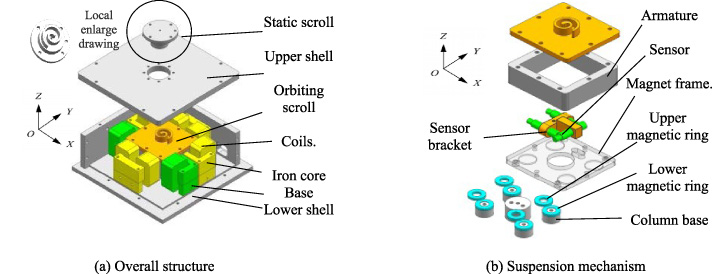
Scroll compressor structure.
Magnetic modeling
The finite element analysis of the large electromagnet in the Y direction is carried out to describe the relationship between magnetic force, current, and air gap length. The parameter diagram is shown in Fig. 2. The parameters are L1 = 57 mm, L2 = 38 mm, L3 = 24 mm, H1 = 41.5 mm, H2 = 28 mm, H3 = 10.5 mm, and the analyzed air gap range d
j
is 0.5 mm ∼ 2.5 mm, with each increase of 0.5 mm, while the current range is 0.5 A ∼ 4 A, with each addition of 0.5 A. The number of turns per coil is 130, and the two coils are connected in series. Figure 3 shows the results of the finite element analysis of an electromagnetic unit in the Y-direction. The electromagnetic force increases with the increase of the current and decreases with the increase of the air gap length. The electromagnet can provide a magnetic force of 15 N at a distance of 2.5 mm air gap, and the current is 4 A. The maximum air gap length for the operation of magnetic-driven scroll compressors is 2.5 mm. The detailed parameters of the scroll compressor can be seen in the article [9]. The magnetic force is described by (1):
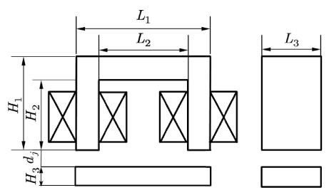
Parameters of U-type electromagnet.
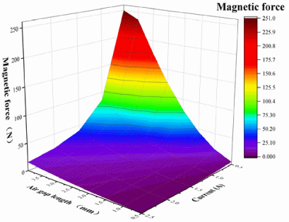
FEM analysis results of magnetic force.
The driving force analysis diagram of the scroll compressor is shown in Fig. 4.
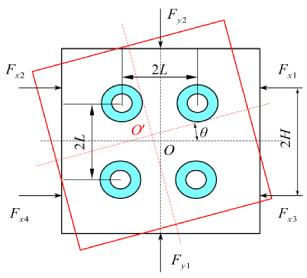
Driving force analysis diagram of scroll compressor.
Under the action of three sets of electromagnetic forces, the scroll compressor has three degrees of freedom, including linear motion in the X-axis and Y-axis directions and rotational motion around the Z-axis. The equations of motion of the scroll compressor operating without compressing the gas are shown in (2).
Linearization of differential electromagnetic iron is:
The derivation of the permanent magnetic force formula is seen in the article [9], which is linearized as:
F m is the mutual magnetic force of a set of permanent magnetic rings, K m is the stiffness coefficient of the permanent magnetic ring, k m = 4.35, δ is the radial displacement. The magnetic properties of the magnetic ring are described in the article [9].
According to the system dynamics equation, the system state space equation is established as:
Where,
The relationship between the three degrees of freedom of the scroll compressor and the breath of the three groups of electromagnetic units:
Design of controller
In this paper, a decentralized control method is used to adjust the air gap length of each electromagnetic unit to achieve the three-degree-of-freedom motion of the scroll compressor. Since the magnetic force of the unit is related to the current and the air gap length, a PID closed-loop control strategy is used in this paper. The air gap length is controlled by changing the magnetic force by controlling the current. The input signal is the deviation signal based on the closed-loop feedback, and its output is the control signal, which is converted into the current input to the electromagnetic unit by the servo driver. The control block diagram of the system is shown in Fig. 5.
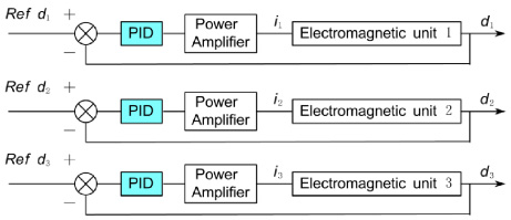
Block diagram of control system.
The closed-loop control block diagram of the platform system is established in MATLAB/Simulink, and the simulation experiment of the displacement response of the system is carried out. As shown in Fig. 6, for the closed-loop step simulation in the X direction of the platform, the initial position of the orbiting scroll is the middle equilibrium point. When the X direction is 0.2 s, a step signal of 0.05 mm is given, P = 30, I = 8, D = 1, and the system is stable after the signal is given for 0.2 s. The corner response simulation is shown in Fig. 7. The parameters of PID remain unchanged. A corner signal of 0.001 rad is given at 0.2 s. After 0.2 s, the system is stable. The results show that the system has good position response characteristics.

Simulation results of displacement response in X direction.
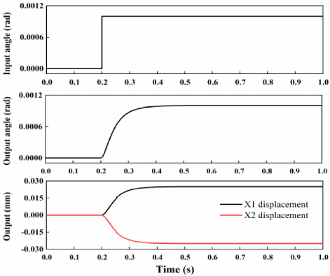
Corner response simulation results.
System integration
The experimental system of the magnetically driven scroll compressor is shown in Fig. 8, which mainly includes the prototype, hardware equipment, and control system. The control system is based on the MicroLabBox produced by the dSPACE company. MATLAB and dSPACE software kits are installed in the upper computer. The power amplifier adopts the current control mode. Pu-05 eddy current displacement sensor of AEC company is used for air gap detection, with a range of 0–2 mm and a resolution of 0.5 μm. The analog output voltage range is −5 V to 5 V.

Control system of principle prototype.
Position step experimental parameters: P = 30, I = 2, D = 0.01. Figure 9 shows the resulting graph of the step experiment. As shown in Fig. 9, a displacement signal of 0.05 mm in the X direction is given at 0.35 s, at which time the current of coil 1 increases rapidly and the current of coil 2 on the other side decreases rapidly, and the electromagnetic force moves the compressor forward, and the system reaches stability after 0.1 s. The experimental results of angular response are displayed in Fig. 10. At 19.8 s, an angular step signal of 0.001 rad is input, and the system generates rotational movement by changing the relative displacement in the x1 and x2 directions. At this time, the current platform of coil 1 increases, the current of coil 3 changes and adjusts rapidly, and the two sets of electromagnets together offset the resistance of the magnetic ring to drive the scroll compressor to rotate clockwise, and the system enters a stable state after 0.2 s. It can be seen that the system has good position response characteristics.

Experimental results of displacement response in X direction.

Experimental results of corner response.
This paper presents a prototype of a magnetically driven oil-free scroll compressor that avoids the use of an anti-spin device and reduces friction to achieve oil-free operation. Firstly, the structure and working principle are introduced. Then the finite element analysis of the magnetic unit is performed, and the mathematical model is established. Finally, system simulation and experimental study are carried out. The results show that the PID control system is used with a displacement of 0.05 mm, a rotation angle of 0.001 rad, and response times of 0.1 s and 0.2 s. The system has good response characteristics and control accuracy and meets the operating requirements of the scroll compressor. The next step of research includes the development of non-linear control algorithms for the control of dynamic loads during the operation of the scroll compressor. This will ensure that the scroll compressor can accurately reach the predetermined position and reduce air leakage under high-speed operation.
Footnotes
Acknowledgements
This research is supported by the National Natural Science Fund of China (Grant No. 52005345, No. 52005344), National Key Research and Development Project (No. 2020YFC2006701), China Scholarship Council, Scientific research fund project of Liaoning Provincial Department of Education (No. LFGD2020002), LiaoNing Revitalization Talents Program (No. XLYC1905003), The Central Government Guides Local Special Funds for Science and Technology Development (Grant No. 2020JH6/10500048).