
Abstract
Cellulose is a promising sustainable material due to its flexibility and high strength. The light scattering characteristics of anisotropic cellulose crystals from various angles with magnetic orientation were experimentally clarified in this study. The intensity of the light scattered from cellulose crystals is reduced by the application of a magnetic field. Therefore, it was suggested that switching the magnetic field would allow the light intensity to be controlled similarly to an attenuator.
Introduction
Cellulose is known to be obtained from wood, and its regenerated products are now used as paper, pharmaceutical coatings, optical films, and cosmetics. It is expected to be a sustainable optical device because it is a lightweight, strong, safe, and secure material [1–7].
According to previously reported studies, cellulose is oriented under a static magnetic field due to the anisotropy of its diamagnetic susceptibility [8–10]. Furthermore, it has been reported that magnetic orientation increases the optical transmittance of microcrystal suspensions [11]. The theory of magnetic orientation states that material is oriented in an energetically stable direction when magnetic energy exceeds thermal energy due to the application of a magnetic field [12–17]. When the magnetic field is turned off, the thermal energy exceeds the magnetic energy again, and the materials return to the state before the magnetic field is applied. These results suggest that the light intensity of cellulose crystals can be controlled remotely and without contact by changing the direction of the magnetic field.
This technique has applications in biomedical diagnostics such as lab-on-a-chip with biocompatible microelectromechanical systems (MEMS) [18–21]. The ability to freely control the crystal’s directions could lead to applications such as focusing lenses for spectroscopy in microfluidic channels [22,23]. Furthermore, crystals in vivo can be detected if near-infrared light is used as the excitation light, making it a good candidate for drug delivery markers. However, previous studies have been limited to the magnetic effect on the transmitted component only, and no studies have focused on the effect of applying a magnetic field on the scattered light.
Generally, as shown in Fig. 1, the forward and backscattering intensities from small particles compared to the wavelength of incident light are approximately equal (ref. 0.1 μm). This is called Rayleigh scattering [24]. On the other hand, for particles that are larger than the wavelength of the incident light, a forward scattering is strong due to diffraction (ref. 1 μm and 10 μm). This scattering is called Mie scattering. The intensity distribution of scattered light may differ if the scattering substance, which are highly affected by diffraction, or anisotropic crystals, are randomly aligned or oriented in a certain direction. Collecting fundamental knowledge from the application to functional optical elements such as reflectors, attenuators, or accelerators is important. In this study, we aim to clarify the angular dependence of the scattered light intensity when cellulose crystals are aligned under a magnetic field.
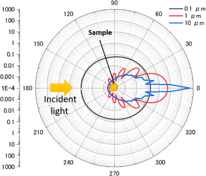
Scattered light distributions of spherical particles with diameters of 0.1 μm, 1 μm, and 10 μm. The following calculation parameters were used: refractive index of solvent (water): 1.33, real refractive index: 1.51, the imaginary refractive index of the sphere: −0.1, wavelength: 532 nm.
Ethylene glycol was mixed with cellulose crystals (CEOLUS FD-F20, Asahikasei chemicals Co., Ltd.). Ultrasound was then applied for 30 min to disperse the crystals. After the samples were allowed to stand for 3 h, the supernatant was diluted at an arbitrary ratio to prepare four different samples. The transmittance of each sample using a 1 cm cell was 77%, 24%, 1.5%, and 0.5%.
Experiments were performed using a multi-angle light scattering measurement system [25] based on a static light scattering measurement system [26] (Fig. S1). A cylindrical sample holder was connected to an optical fiber, and microcrystals in suspension were irradiated with laser beams of various wavelengths in parallel, and the scattered light from the crystals was detected. The scattered light from the sample was detected by placing ten optical fibers at 15° intervals from the direction of incidence at θ = 10° to 150°. Scattered light from all angles was directed to a single photodetector for almost simultaneous detection in a short time by moving the fiber holders at equal intervals on an automated stage. To measure the scattered light intensity before and after applying the magnetic field, the sample holder was placed in an electromagnet with 60 mm between poles (maximum strength of 0.5 T).
Results and discussions
Figure 2 shows images of the cellulose crystals used in this experiment. (a) is an SEM image. The crystals in the solution were about 5–20 um longitudinally, and crystals of different shapes (whisker-like, plate-like) were present. (b) shows polarized light microscope images before and after applying a magnetic field. The images show the direction of the magnetic field and the crossed nicole. (i) is before the magnetic field application, and the crystals are randomly arranged. When a magnetic field of 0.3 T was applied, the long axis of the crystals was oriented perpendicular to the magnetic field direction. In (ii), many crystals appeared when the crystal axis and the polarization axis were set to 45° (i.e., diagonal position). However, in (iii), when the crystal axis and the polarization axis are set parallel or perpendicular (i.e., extinction position), many crystals were disappeared. These results show that crystals can be highly aligned even at 0.3 T.
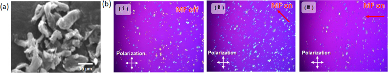
SEM and microscope images of the cellulose crystals (a) SEM image (b) polarized microscope images before and after application of the magnetic field. (i) without magnetic field, (ii) diagonal position. (iii) extinction position.
Figure 3 shows the time course of reflected light intensity in the 90° direction when a 0.5 T magnetic field is applied to the cellulose crystals. The experimental system, where the incident direction, magnetic field direction, and detected direction were orthogonal to each other. After about 45 s of activating the magnetic field was turned on after about 45 seconds, the light intensity, which had been stable, decreased rapidly. Then, when the magnetic field was turned off after about 95 seconds, the reflected light intensity gradually recovered. when the magnetic field was turned off. After that, repeated switching of the magnetic field switching resulted in a similar decrease in light intensity.
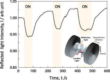
Time course of reflected light intensity under magnetic field. Insert: experimental condition.
Figure 4 shows the electric field intensity distribution simulation using the FDTD (Finite-Difference-Time-Domain) method. FDTD simulations were performed using commercial software (OptiFDTD, Optiwave Systems Inc.). The CPU used was Intel Xeon E5-2609v4 with 64-GB memory, and the computation time was ∼24 h using most of the memory. (a), (b), and (c) show the diffraction of light generated when the cellulose crystal axis is placed at various orientations relative to the incident axis. The incident light was a polarized electromagnetic wave of wavelength 𝜆 = 500 nm, emitted from the left toward the right side. The lower arrow indicates the strength of the side scattering when normalized by the strength of the forward scattering. The long and short sides of the crystal were 5 μm and 1 μm, respectively. At this crystal size and wavelength of the incident light, the scattering is dominated by Mie scattering. In other words, the strongest scattering in all states is the forward scattering. Side scattering is very small compared to forwarding scattering in the state (a) when normalized by the intensity of forwarding scattering. In states (b) and (c), the forward scattering is smaller than in states (a), so the side scattering is relatively large when normalized by the forward scattering. These results are consistent with previous experimental interpretations [27]. Here it is considered that the crystals in states (a), (b), and (c) uniformly exist without a magnetic field. If a magnetic field is applied in the vertical direction (y-direction), the crystals in the state (c) rotate in the direction of state (a) or (b). The change in the intensity of side scattering slightly decreased compared to before the magnetic field was applied. At least, the side scattering does not increase more than before orientation. This is reasonable because the reflected light intensity was decreased by the application of the magnetic field in Fig. 3.
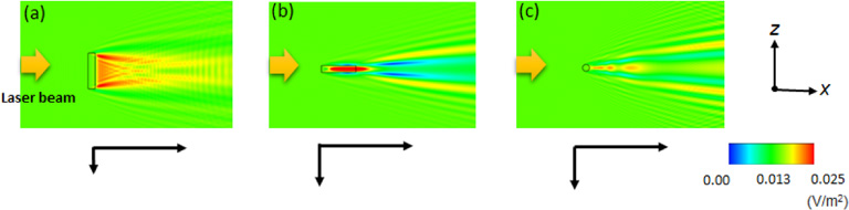
Analysis of electromagnetic fields using FDTD simulation. Scattered light property from cellulose crystal aligned (a, c) perpendicular (b) parallel to the incident light. The following calculation parameters were used: the refractive index of solvent (Ethylene glycol) was 1.43. The refractive index (Cellulose) was 1.51.
Figure 5 shows the scattering distribution when a laser beam of 532 nm wavelength is incident on the crystals suspension with no magnetic field applied. The detection angles from 10° to 150° are measured values, and the values from 210° to 330° are plotted the same as those from 10° to 150°, assuming that scattering is vertically symmetric. The angular distribution of scattered light obtained for the dilute samples (the transmittances are 77% and 27%) was most similar to the Mie scattering distribution obtained from the larger particle, as shown in Fig. 1. However, the distribution was similar to the scattering distribution for isotropic particles for concentrated samples (the transmittances are 1.5% and 0.5%). This may be due to the considerable multiple scattering effects. As the scattering times increase with high concentration, the more likely the scattered light will spread perpendicular to the incident direction. Therefore, the scattered light distribution will be similar to isotropic. In general, it is very difficult to calculate multiple scattering in electromagnetic field analysis.
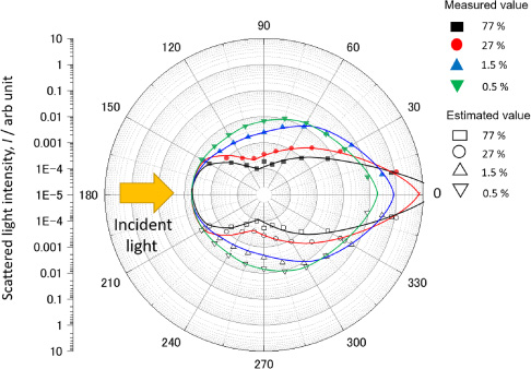
Angular distributions of scattered light intensity in the absence of an applied magnetic field. The closed symbols indicate the measurement results, and the lines indicate the angle distributions assumed from the measurement results.
Figure 6 shows the scattered light intensity when a magnetic field (0.5 T) is applied to each sample with different transmittance, plotted as a change ratio relative to the scattered light without a magnetic field (Fig. 5). The side scattering decreased when a magnetic field was applied to the dilute samples (77% and 27%), supporting the result in Fig. 3. Magnetic orientation affected forward and backscattering more than the side scattering. The effects of the magnetic orientation significantly differ for the concentrated samples (1.5% and 0.5%) compared to the dilute samples. In the dilute samples, the scattered light was greatly decreased in the forward and backward directions, while in the concentrated samples, the scattered light was rather increased at forward directions. No significant differences were found depending on the wavelength of the excitation light.
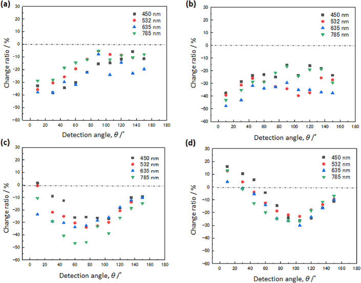
Change ratio of scattered light intensity induced by an applied magnetic field in the sample of each transmittance. Each symbol indicates the wavelength of the incident light (a) Transmission of the sample is 77%. (b) 27% (c) 1.5% (d) 0.5%.
It is considered that the decrease in the total scattering cross-section causes a decrease in light intensity with a magnetic field in diluted samples. There will be a higher probability of light incident on the sample from a direction perpendicular to the incident direction because the angular distribution of light scattering tends to be isotropic in concentrated samples due to multiple scattering, as shown in Fig. 5. Therefore, there are instances where the magnetic orientation causes scattered light to increase. In this experiment, it was shown that the light intensity could be changed up to 50% by the application of a magnetic field. The refractive index difference between the scattering medium and the solvent should be considered to change the light intensity more significantly by switching the magnetic field. We will promote experiments for applications to devices.
The scattered light characteristics of cellulose crystals at various angles under a magnetic field were experimentally clarified in this study. The scattered light was discovered to be freely controllable by varying the magnetic field, although the sample’s condition is crucial. When a magnetic field is applied to a dilute suspension, the scattered light decreases, with substantial attenuation rates in the forward and backward directions. In contrast, the scattered light was improve at forward directions in a concentrated suspension. It is shown to have potential and promising applications in optical devices that operate in low magnetic fields, such as attenuators and focusing lenses. The detection angle should be considered depending on the sample condition since this magnetic field effect affected the sample concentration.
Footnotes
Acknowledgements
The part of this work was supported by JSPS KAKENHI grant number 19K14994.