
Abstract
In the production line of thin steel plates, contact conveyance by rollers causes deterioration in the surface quality of the plates. To solve this problem, our research group has been continuously investigating the optimal placement of permanent magnets in hybrid magnetic levitation systems. In this study, when a thin steel sheet was magnetically levitated, the effect of the horizontal electromagnet position on the gap between the steel sheet and the permanent magnet was investigated through a permanent magnet configuration optimized using a genetic algorithm.
Introduction
Magnetic levitation without a superconductor (i.e., normal-conduction magnetic levitation) does not require low-temperature control and can be applied as long as the object to be levitated is a magnetic material [1–4]. In particular, the introduction of non-contact support and transfer technology in the manufacturing process is expected to solve the problem of surface quality deterioration, such as scratches and peeling of the plating layer of thin steel plates, and to yield higher quality thin steel sheets. However, thin steel plates have low bending rigidity and deflection, and complex vibrations occur at points that the levitating support force does not reach, making contactless support and transport of flexible structures extremely difficult. For this reason, the construction of a magnetic levitation system that considers the levitation object as a flexible structure and considers its static or dynamic response characteristics is an extremely important issue. Generally, to levitate such an object stably, it is necessary to install a large number of electromagnets to suppress deflection by minimizing the areas that the attractive force does not reach, but this increases the control input and costs. In a previous report, our research group proposed a method in which the attractive force generated by permanent magnets was used to assist the levitation support force from electromagnets [5]. The deflection of the steel plate was suppressed by placing permanent magnets at equal intervals around the levitating electromagnets, thereby improving levitation stability. However, to obtain higher levitation stability, it is necessary to consider parameters such as the “number of permanent magnets”, “arrangement of permanent magnets”, and “distance between permanent magnets and steel plates”. However, these parameters have many possible combinations, which complicates the process of obtaining an optimal permanent-magnet arrangement experimentally.
Therefore, a genetic algorithm (GA), which is an optimization algorithm, was used to search for the optimal placement of permanent magnets that could best suppress the deflection of steel plates. The GA evaluated the steel plate shape when permanent magnets were installed and searched for parameters that could suppress the deflection. The overall deflection of the steel sheet was evaluated by calculating the average deflection at each analysis point of the steel sheet geometry, while the local deflection was simultaneously evaluated from the maximum deflection. Levitation experiments were conducted using the obtained permanent magnet configuration, and it was confirmed that the levitation stability improved [6,7]. Furthermore, we searched for the arrangement of permanent magnets for the levitation aid that could best suppress the deflection of the magnetically levitated steel plate under tension applied in the horizontal direction using the GA, conducted levitation experiments, and confirmed that the deflection was suppressed [8]. However, the validity of the optimal arrangement of permanent magnets when the distance between the center of the horizontal electromagnets changes was not verified. In addition, these works are compared to the case without permanent magnets or with permanent magnets uniformly arranged without GA to show the advantage of GA. Therefore, it is not clarified how the suppression of the static deflection of the steel plate improves the dynamic levitation stability. In this study, we obtained optimal arrangements of permanent magnets in 3 types of conditions by using GA and conducted levitation experiments using the obtained 3 arrangements to clarify the relationship between analytically obtained static shape of the steel plate and actual dynamic behaviour of the levitated steel plate.
Outline of electromagnetic levitation control system with permanent magnets.
Plan view of electromagnet arrangement.
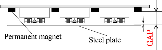
Side view of the gap between the permanent.
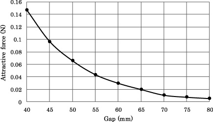
Relationship between the gap and attractive force in the analysis.
Overview of magnetic levitation model
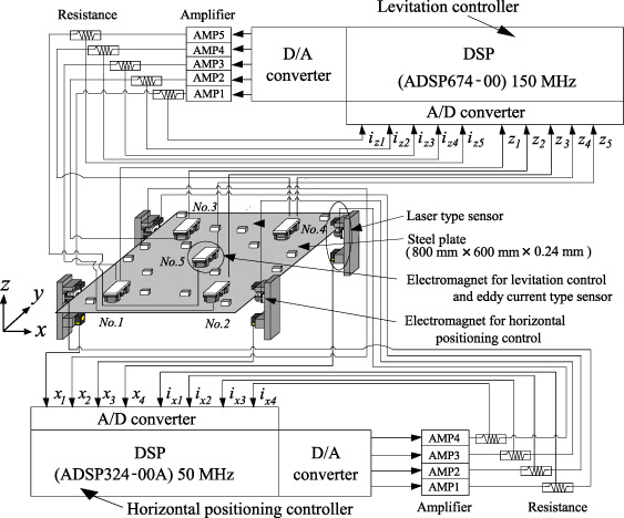
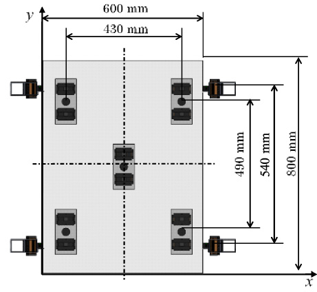
A schematic representation of the magnetic levitation system is shown in Fig. 1. The magnetic levitation system consisted of a vertical levitation control system and permanent magnets. The object to be floated was a rectangular galvanized steel sheet (SS400 material) with a length (l) of 800 mm, width (w) of 600 mm, and thickness of 0.24 mm. An electromagnet unit that levitates the steel plate was installed at one location in the center of the plate and at four locations around the plate. The distance between the surface of each electromagnet and the surface of the steel plate was controlled at 5 mm to levitate the steel plate. Horizontal electromagnet units consisting of an electromagnet and a transmission laser displacement sensor were installed near the longitudinal edge of the steel plate at four opposing locations, and positioning control was performed such that the distance between the electromagnet surface and the edge of the steel plate was 5 mm. The levitation and horizontal electromagnet units were installed as shown in Fig. 2, and the magnetic levitation system had a structure that allowed the position of the horizontal electromagnets to be changed. The distance between the centers of the electromagnets of the horizontal directional electromagnets is 540 (mm).

Bird’s eye view of shape of steel plate levitated with only electromagnets.
Amplitude of permanent magnets with attractive force at each distance between permanent magnets.
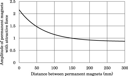
In this system, the attraction force of the permanent magnets is applied to areas where the attraction force of the electromagnets is not applied, thereby suppressing the deflection of thin steel plates during levitation and improving the levitation stability. The shape of a thin steel plate during levitation is obtained by an analysis when the attractive force of a permanent magnet is applied. The permanent magnet (30 mm × 30 mm × 15 mm) is made of ferrite and has a surface flux density of 0.12 T and a magnetization direction in the N-pole on the steel plate side. The attractive force generated by the permanent magnet on the steel plate varies with the distance between the surface of the permanent magnet and the surface of the thin steel plate (hereafter referred to as “Gap”), as shown in Fig. 3. Figure 4 shows the relationship between the gap obtained from the electromagnetic field analysis and the attractive force generated in the steel plate. The amount of deflection of the thin steel plate under the action of gravity and permanent magnet attraction was calculated from the static deflection equation of a thin steel plate.
In our previous studies, we confirmed from electromagnetic field analyses and experiments that the attractive force generated by permanent magnets increases with the distance between the magnets owing to the interaction of the magnetic fields in an arrangement of multiple permanent magnets with the same polarity. Figure 6 shows the relationship between the ratio of the attraction force owing to the interaction of the permanent magnets to the attraction force acting on the steel plate when one permanent magnet is installed and the distance between the permanent magnets. In this process, once the permanent magnet arrangement is generated, the distance between each permanent magnet is calculated, and the attraction force of the permanent magnets is varied according to the distance to the closest permanent magnet to calculate fPM.

Flow chart of genetic algorithm for finding optimal arrangement of permanent magnets.
Results of evaluation value J at Gap between permanent magnets and steel plate.
To search for the optimum number and arrangement of permanent magnets and gaps that effectively suppress the deflection of the thin steel plates, an evaluation value was set from the shape of the steel plate at which the attractive force from the permanent magnets was applied by a difference analysis. The average deflection (J
Z
) is defined by Eq. (4).
Search method for optimal placement
Because the attraction force of permanent magnets varies with the gap, the optimal number and arrangement of permanent magnets were optimized to effectively suppress the deflection of thin steel plates at each gap. However, experimentally searching for optimal values is difficult because of the large number of search patterns. Therefore, we used the GA to search for the optimal permanent magnet arrangement. The search program using GA was developed with MATLAB by our research group and previously confirmed that this program can solve basic problem and agreed with the solution. The flowchart of the GA is shown in Fig. 7 and search conditions of GA is shown in Table 1. First, the number of permanent magnets and the initial configuration were randomly determined (initialization in Fig. 7 the number of initial population occurrences was 32). Subsequently, the shape of the thin steel plate when gravity and the attractive force of the permanent magnet were applied was calculated (deflection analysis of the steel plate), and the value of J was calculated from Eq. (6) (calculate the evaluation value). This evaluation function was used to select candidates for the optimal placement (selection: the elite conservation law was applied to unconditionally exclude the top two positions). A new placement was generated with a certain probability to approach the optimal solution (uniform crossover: a uniform crossover was used, and the crossover rate was 90%). However, because a group of similar placement patterns may fall into a local solution, the placement was distributed with a probability of 1% to ensure diversity (mutation). The search was terminated when the evaluated value did not change over a certain number of generations; however, preliminary studies confirmed that similar values were obtained for 300 generations or more. In this study, the calculation was terminated when the final value of the evaluation function remained unchanged for 300 generations. The gaps were 50, 55, and 60 mm. Owing to the nature of the GA, the obtained optimal value may fall into the local solution; thus, 10 searches were conducted with the same gap. The distance between the centers of the horizontal electromagnets (a) was set to 540 mm, and the steady-state value of current in the horizontal electromagnets was set to 0.5 A. These values were used for the horizontal electromagnets.
Search conditions of GA
Search conditions of GA
Optimal arrangement of permanent magnets.
Time histories of displacement of steel plate in case of optimal arrangement at each gap.
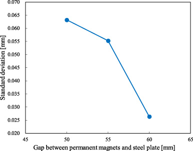
Standard deviation at each gap.
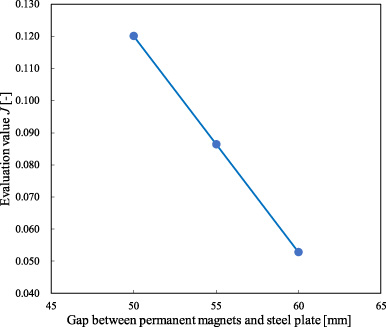
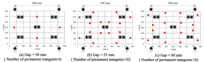
From the number, arrangement, and gap of permanent magnets obtained by the GA, the deflection of a thin steel plate can be obtained by the FDM using Eq. (1). The average deflection (J Z ) and the maximum deflection (J D ) were calculated. Using Eq. (6), J was obtained from these values and the weight coefficients. Figure 8 shows the value of J for 10 searches for each gap between permanent magnets and steel plate The search result with the smallest value of J was considered as the optimal value The lowest value of J was obtained when the gap was 60 mm, confirming the tendency of J to decrease as the gap increased. When the distance between the permanent magnet and the steel plate was too small, the attraction force of the permanent magnet on the steel plate was too large, and the permanent magnet could not suppress the deflection. Figure 9 shows the arrangement of permanent magnets that minimized the value of J for each gap, confirming that the optimal arrangement and number of permanent magnets obtained for different gaps are different.
Levitation experiments
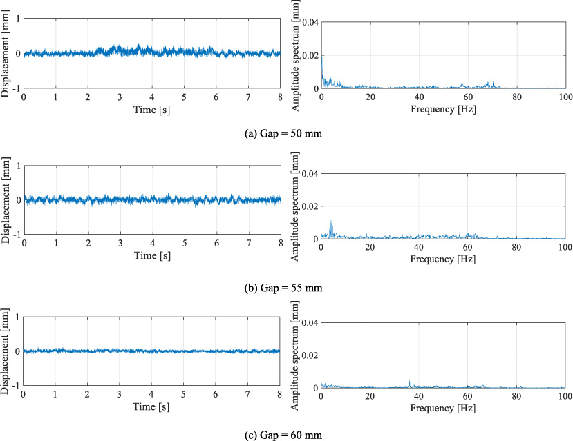
Using the optimal arrangement of permanent magnets at each gap obtained in Section 3, we performed levitation experiments on thin steel plates under the same conditions as in the GA search. This experiment was conducted five times for each gap, and the standard deviation of the displacement in the measured steel plates was calculated. Figure 10 shows the displacement of the steel plate, time history, and waveforms measured by the surrounding electromagnet (No.1 in Fig. 1) during the levitation experiments at each gap. There was a trend of decreasing vibration as the gap increased. It can also be observed that the frequency of oscillation changed significantly for gaps of 50 and 55 mm. The relationship between the gap and the displacement standard deviation is shown in Fig. 11. It was confirmed that the displacement standard deviation tended to decrease as the gap increased, and the trend was similar to that of the value of J at each gap obtained in the GA search.
Conclusion
In this study, for a magnetic levitation system with horizontally oriented electromagnets, the search for the optimum arrangement of permanent magnets using the GA was performed by varying the gap, and levitation experiments were conducted using the obtained optimum arrangement of permanent magnets. From the levitation experiment, it was confirmed that the displacement standard deviation of the thin steel plate decreased as the gap increased, and the trend was similar to that of the value J in the GA search, indicating that the dynamic steel plate vibration can be suppressed if a permanent magnet is installed such that the static steel plate deflection during levitation is reduced, which was obtained through analysis. In the future, we plan to expand the distance between electromagnet centers and the range of gaps to search for the optimal arrangement of permanent magnets, and we plan to verify the validity of this method in more detail by performing levitation experiments.