
Abstract
As promising non-destructive testing (NDT) method, magnetic flux leakage (MFL) testing has been widely applied for steel structure detection. However, magnetic flux leakage (MFL) signal collected by the sensors is weak, especially for the small diameter wire rope. The methods of using the traditional circular coil sensors, or increasing the number of magnets is ineffective in some situations. This study proposes a new method of highly sensitive long-strip-shape coil sensors with an analogue signal processing circuit used to detect wire rope in the timing belt of wind turbines. It is investigated by theory analysis, circuit simulation, and experiment conduction. The circuit is used to amplify the weak signal and filter high-frequency noise to obtain a high signal-to-noise ratio (SNR). Experiments show that the resolution of the method can reach 3 broken wires of 0.1 mm wire diameter, and the method can not only obtain a high SNR signal but also have good repeatability. Meanwhile, this method will have great significance in practical applications and provide some solutions for other similar NDT projects.
Keywords
Introduction
As efficient non-destructive testing (NDT) method, magnetic flux leakage (MFL) inspection is performed based on MFL produced at an area of defects on a ferromagnetic specimen in a saturated magnetized situation [1]. Moreover, the MFL method can ignore non-ferromagnetic mediums such as dirt, dust, or lubricating oil. Due to these advantages, MFL is especially fit for steel structure inspection, such as pipelines [2], steel pipes [3], bridge cables [4], rail tracks [5], and wire ropes [6].
The MFL method uses a magnetizer to generate a magnetic field into the specimen. In addition, coil sensors pick up the leakage magnetic field caused by defects of the specimen [7]. For an extended period, lots of work were committed to proposing and optimizing magnetization [8], sensing [9], and signal processing methods [10]. Recently, with the rapid development of artificial intelligence, kinds of data processing algorithms are also applied for defect recognition, classification, and quantification [11].
It is well-known that MFL detection is sensitive to large defects in a relatively large-diameter wire rope. However, with the increasing lift-off distance or decreasing diameter of wire ropes, the magnetic leakage flux signal in the defect area is too weak to detect. As a result, there are some limitations to using the MFL method in practical equipment inspection. Such as in the timing belt of wind turbines, a certain number of wire ropes, whose wire diameter is about 0.1 mm, are embedded in the timing belt to transfer mechanical power from its vanes to the generator. The height of wind turbines is about 100 m, and the wind plant is generally located in a remote location. Therefore, it is challenging to maintain and replace belts and essential to realize the extraction of the MFL weak signal.
In this paper, to increase the detection sensitivity of the MFL method, the MFL theory was investigated, and a new method of highly sensitive long strip shape coil sensors with an analogue signal processing circuit was proposed. The following sections are respectively arranged as MFL detection principle, and coil sensor parameters were analyzed in Section 2; the circuit design and simulation result were presented in Section 3. Section 4 showed the process of the weak MFL detection signal extraction experiment. Discussion and conclusion are respectively put forward in Sections 5 and 6.
MFL detection and coil sensor parameters
MFL detection principle
Magnets are placed on both ends of the magnetizer, and a magnetic yoke connects them to form a closed magnetic circuit. When the magnetizer goes through the defect, defects will distort the magnetic flux distribution. Then, the magnetic flux leaks into the air from the inside of the wire rope. A magnetic sensor such as a coil can detect the MFL and transfer it to the electric signal, which will be processed by the circuit and software calculations.
According to Faraday’s law of induction, the induced electromotive force (EMF) in the induction coil is expressed as:
Considering magnetic flux 𝜙 are multiplied by magnetic flux density B and induction coil area S. According to previous studies [11], the magnetic leakage flux in nearby defect areas is determined by a magnetic circuit. The magnetic circuit includes magnets, yokes, wire ropes, and defects. After the magnetic circuit was decided, the MFL was determined. Therefore, if the shape of the coil is rectangular and the velocity of translation is given, from Eq. (1), assuming B remains constant, it can be proposed as:
Based on the theoretical analysis above, as shown in Fig. 1, six long-strip-shape coils forming a serial array were determined. Each has the same size, with a length, width, and thickness of 8.7 mm, 0.5 mm, and 1 mm. The diameter of copper wires is 0.08 mm, and the number of turns is 194. In fact, according to Eq. (2), the orientation of the coils’ length should be perpendicular to the movement direction.
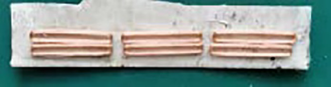
Six long-strip-shape coil sensors.
Considering the application background of wire ropes is mostly in highly harsh working conditions such as mines or oceans, there will inevitably be electromagnetic interference and other noise. Thus, defect signals will be quickly overwhelmed with noise.
The circuit configuration was divided into 2 modules, the first was amplifying circuit, and the second was a low pass filter. For the amplification, the choice of a non-inverting amplifier or inverting amplifier depends on the high input impedance. Because the resistance of the long strip shape coil selected this time is about 200 Ω leading to the resistance of the signal source cannot be ignored. If the input impedance of the amplifier circuit is small, there will be a certain proportion of signal loss at the source. Eventually, the operational amplifier OPA2188 was selected, which has a non-inverting amplifier, as shown in Fig. 2(a).

(a) Operational amplifier composed of OPA2188. (b) DC bias circuit.
Meanwhile, a DC bias voltage of 2.5 V supplies the operational amplifier, as shown in Fig. 2(b), to ensure the symmetry of the non-inverting input and inverting input circuits. Thereby effectively eliminating the influence of the static base current on the output voltage and reducing common mode noise. Considering the signal collected is altering voltage, the output voltage swings around 2.5 V. A more excellent dynamic range can be achieved because of low common mode noise caused by a DC bias voltage. In parallel with feedback capacitors, the existing feedback resistors are utilized to form active filters. Connect the feedback capacitor between the two stages to compose a second-order low-pass filter. After simulating, the amplification factor is 3800 when the frequency is 50 Hz. In practical applications, the factor is about 1000 at 50 Hz. The cut-off frequency is 155 Hz. Furthermore, the PCB board in Fig. 3 was verified through experiment.

PCB.
The wire rope of the wind turbine is shown in Fig. 4, the wire diameter is less than 0.1 mm, and the thickness of the timing belt is 2 mm. The wire ropes are made of low-carbon steel, and their permeability is about 1000. When the traditional cylindrical coil detection is used to excite a sufficiently strong leakage magnetic field energy, the number of magnetizers should be increased. However, the internal space of wind turbines is limited, and the detection probe is required to be as light as possible. Therefore, it is not feasible to increase the amount of magnetization to increase MFL.
To implement the wire rope detection in the timing belt plate, a minimum magnetization structure used in this experiment is a magnetic bridge circuit probe, as shown in Fig. 5. The side length of the two square magnets made of NdFe52, whose coercivity is 955 kA/m, the remanence of them is 1.44 T. The relative permeability along the axial direction is 1.21 [12] is 30 mm, and the magnetic yoke’s length, width, and thickness are respectively 70 mm, 30 mm, and 30 mm. Besides, the volume is much smaller than the requirements of the detection environment. Afterwards, three types of damage, represented in Fig. 6, were sequentially made on the timing belt sample: Three broken wires on one wire rope, three broken wires on two wire ropes, and nine broken wires on three. Finally, using the six long-strip-shape coil array and designed amplification circuit, the test MFL signal with an ideal signal-to-noise ratio was collected, as expressed in Fig. 7. The largest, middle and smallest amplitudes of sharp represent nine broken wires, three broken wires in two wire ropes, and three broken wires in one wire rope, respectively. The probe obtains the signal with reciprocating motion, whose speed is about 0.2 m/s. The first group is from 2000 ms to 4000 ms, and the second group is from 6000 ms to 9000 ms. The defects’ signal peak-to-peak value amplitude is about 1.3 V, 0.38 V, and 0.29 V; their SNR is 16.25, 5.01, and 3.75. Three broken wires of 0.1 mm wire diameter inside the belt can be detected using the MFL method.
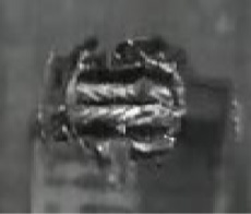
Wire rope in the timing belt.
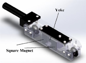
Detector model with miniature magnetizer.
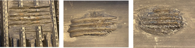
(a) Three broken wires in one wire rope. (b) Three broken wires in two wire ropes. (c) Nine broken wires.

Signal collected using MFL method.
No study to date is related to highly small-diameter wire rope detection, whose wire diameter is only about 0.1 mm. Figuring out the detectable most minor wire diameter limitation of the MFL method using permanent magnets to excite magnet leakage flux is a future development trend for MFL detection. Considering the actual working condition, the magnetization using a permanent magnet has the advantages of convenience and efficiency. It can provide a sufficiently stable external excitation field, making the detection signal more reliable. A strong magnetization field is the energy source for the detection of minor defects, deep-buried defects, and even detection at a large lift-off distance. In the detection scenario mentioned above, magnets with large volumes (magnetic energy products) cannot be used due to the limitation of space in the wind turbine. Therefore, other methods to improve the detection sensitivity should be found from the back-end design.
Our results found that the same three broken wires could be detected with almost the same amplitude, whether on a single wire rope or two wire ropes. Compared with three broken wires, the MFL signal amplitude of nine broken wires is three times that in the case of three broken wires. This phenomenon proves that the peak-to-peak value of the radial component of the damage leakage magnetic field presents an approximately linear characteristic within a specific acceptable error range and provides a basis for quantitative analysis under signal processing. Meanwhile, six long-strip-shape coils are connected in series and arranged in an array to increase the space measurement range.
However, a reliable study must be conducted on the linear range and measurement range of the MFL detected by a coil array. For the sensitivity of the type of coil, using the long side is better than using the short side based on Eq. (2), which suggests that the MFL signal is related to different placement poses of different kinds of coil arrays. Many pieces of research mainly focus on the influence of various coil parameters on detection sensitivity and linearity [13], which show a contradictory relationship between sensitivity and linearity. Therefore, on the one hand, the MFL signal of a certain number of broken wires will be within the linear detection range of the coil. On the other hand, it is possible that the small size or small quantity of broken wires cannot be identified due to low sensitivity. Finding a balance point between the two characteristics of magnetic sensors is a main problem for the sensors in the field of MFL detection in the future. We only theoretically analyze the EMF as proportional to the long side length. One concern about this finding is that there is no comparison between the different shapes of coils. With the different number of turns, wire diameters, sizes, and other parameters, coils sensitivity will be different. Another limitation of this research is that no sensitivity range of the coil array is explored, so the MFL signal of the single broken wire is not presented. However, our studies prove that the method of changing high-sensitivity magnetic sensors and using circuit noise reduction will have great significance in practical applications and provide some solutions for other similar NDT projects.
For future work, the magnetization should be enhanced, the experiments of the different shapes, sensitivity and linearity of the coil could be performed, and any new data processing algorithm may also be applied.
Conclusion
This paper proposes a new method of highly sensitive long strip shape coil sensors with an analogue signal processing circuit for detecting tiny diameter wire ropes in the timing belt of wind turbines. It is found that the resolution of the method can detect 3 broken wires of 0.1 mm diameter, and the method can obtain a high SNR signal and have good repeatability. In future work, this method will have great significance in practical applications and provide some solutions for other similar NDT projects.
Footnotes
Acknowledgements
This research was funded from Research on Operation and Maintenance Technology of Balance Weight Wire Rope programme, Changjiang River Administration of Navigational Affairs, MOT, grant number SXHXGZ-2021-2.