
Abstract
As an important actuator component, the electromagnetic linear actuator has a significant impact on the performance of fully flexible variable valve trains. Aiming at the shortcomings of the conventional moving coil electromagnetic linear actuator (MCELA) with low force density and insufficient end-passive self-holding ability, a novel compound electromagnetic linear actuator (CELA) integrating the advantages of MCELA and the moving iron electromagnetic linear actuator (MIELA) was proposed in this work. The CELA has two operating modes, including single drive mode and cooperative drive mode, and its loss variation is different from that of the single MCELA or MIELA. Firstly, the current and displacement curves under different operating modes were obtained through experiments, which were then used as the excitation source to quantitatively analyze the copper and iron losses under different working conditions by means of 3D finite element simulation. The loss distribution and ratio of CELA under typical operating conditions were discussed in detail. The effects of stroke and valve opening duration on CELA losses were analyzed. The results show that there are significant differences in the loss variation rules between the two operating modes, the losses increase as the working stroke increases in single drive mode. In the cooperative drive mode, the losses are much greater than in the single drive mode, with the losses decreasing in the initial stage and then increasing as the stroke increases. None of the valve opening durations had a significant effect on losses. This study provides a reference for loss studies of other novel electromagnetic linear actuators.
Introduction
Automobile industry is one of the key industries for national economy and plays an important role in social development. However, the environmental problems and energy security problems brought by the development of automobile industry are becoming increasingly prominent. Therefore, the development of new energy-saving vehicles is a breakthrough to solve problems in energy security, climate change, environmental protection and structural upgrading [1]. Fuel cell [2,3], solar cell [4,5] and other new energy vehicle technologies [6–9] are the development directions of the future automobile industry. However, there is still long way to go to realize the popularization of these technologies. As a classic vehicle power source, the internal combustion (IC) engine still holds a significant market share, so it is necessary to study the energy-saving emission reduction technology of internal combustion engine at present. Many automakers and research organizations are now making efforts on the optimization of internal combustion engine technology so as to realize energy conservation and emission reduction [10–12]. Camless valve mechanisms are key enablers of other advanced engine technologies, and the research on camless valve trains is crucial for enhancing the power and efficiency of automobiles while lowering energy loss and reducing pollutant emissions in the face of increasingly limited petroleum resources and severe environmental challenges [13].
A low cost, high efficiency actuator, as well as a highly precise and fast response control system are the main development bottlenecks for the camless valve train [14]. Since existing MCELA has the disadvantages of low force density and lacks of terminal passive self-holding capability, and the MIELA has high energy loss, Fan et al. [15] proposed a novel compound electromagnetic linear actuator (CELA) integrating the advantages of MCELA and MIELA. Figure 1 shows the structure of CELA proposed in this paper. It has the advantages of high efficiency, energy-saving, fast response, and high precision [16].
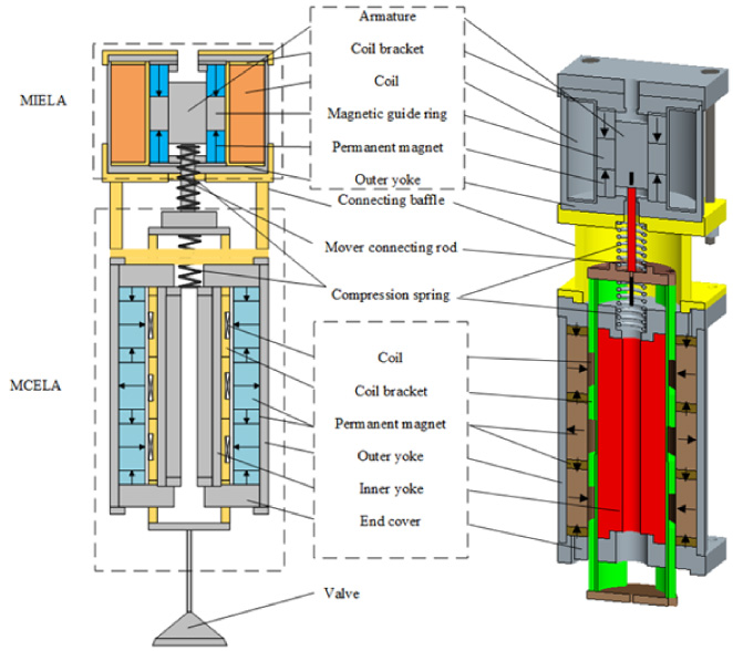
Structure of CELA.
CELA has excellent performance, but its performance gains were extensively limited by its losses. The loss will affect the energy efficiency of the electromagnetic linear actuator and reduce the work efficiency. Excessive loss accumulation will produce a thermal effect, resulting in damage of insulation layer, permanent magnet failure, and other adverse effects, thus shortening the service life of winding and reducing the reliability and stability of CELA operation. Therefore, it is of great significance to analyze the loss reduction of CELA and improve the performance of electromagnetic driven valve train.
Current researches on motor losses mainly include copper, iron, mechanical, and other losses [17,18]. The loss distribution of CELA is different from that of conventional motors. Dai et al. [19] studied the loss distribution law of the MCELA preliminarily, in which the mover remained locked and the effect of exhaust gas was neglected. Tan et al. [20] simulated the dynamic performance by the 3D finite element method considering the eddy current loss of soft magnetic material of MIELA, and results showed that the eddy current had a significant effect on the dynamic performance. McIvor et al. [21] demonstrated the performance improvements achieved by the electromagnetic linear actuator of a flapping wing micro aerial vehicles when the intrinsic frequency was properly tuned, and it was found that the input energy consumption was reduced to 13% of the original level. But in the aforementioned work, the dynamic distribution of the loss with the variation of the actuator’s working stroke and duration was not considered.
As a follow-up study, this paper will conduct an in-depth analysis of the loss distribution of the novel CELA under different operating modes and different working conditions. The dynamic distribution of CELA’s loss with opening and closing stroke in a working cycle will also be studied and discussed. The novel compound electromagnetic linear actuator (CELA) has two operating modes (the single drive mode and the cooperative drive mode), and the loss variation in cooperative drive mode is quite different from that in single drive mode, which will be expanded in details. This will lay a foundation for analyzing the temperature field distribution and temperature rise of the compound electromagnetic linear actuator and revealing the influence of temperature change on the electromagnetic performance of the compound actuator. Moreover, it also provides theoretical basis for improving performance and promoting electromagnetic valve train.
Structure of CELA
Figure 1 shows the structure of the compound electromagnetic linear actuator. Through the connecting baffle, MCELA and the hybrid excited MIELA are joined in series and attached to each other. The movement parts are connected in a strict manner. The two compression springs are kept in a constant state of compression.
MCELA is the main driving element, which consists of an outer yoke, an inner yoke, permanent magnet and a moving coil. The coil bracket is directly connected to the valve, and the valve motion is controlled by controlling the coil current. MCELA has linear output force and good control performance owe to the use of the Halbach array [22–24] in the internal magnetic field to increase the strength of the air gap magnetic field.
As an auxiliary driving component, MIELA is mainly consisted of armature, permanent magnet, magnetic guide ring, coil winding and outer yoke, etc. The armature and moving-coil bracket are fastened by connecting piece. Based on the principle of minimum reluctance, MIELA realizes the control of output force by controlling coil current. In addition, MIELA has end-passive self-holding capacity.
The working principle of CELA can be divided into two modes depending on the load extent under different operating conditions. When the load is small, only MCELA is energized, and the output electromagnetic force drives the valve. On this basis, MIELA passively follows, and the system energy loss is reduced. Cooperative drive control is performed when the load is large. The coils of both MCELA and MIELA are energized, and the same direction electromagnetic force they output drives the valve, and MIELA acts as a booster to improve the driving ability of the system. The CELA integrating the advantages of MCELA and MIELA has the following features: High efficiency and energy saving capacity: the actuator has a large driving force to meet the needs of various occasions, and also has end-passive self-holding capacity at the end of the stroke to reduce the electric loss at work. High precision: MCELA has a linear output force and strong controllability; through the cooperative control of two actuators, the accuracy is improved. Fast response: The driving capacity is increased by the superposition of the output forces of MCELA and MIELA, which can enhance response performance and broaden the range of application.
Numerical model of loss
Since CELA is a new type of structural actuator, there is no specific definition and demarcation of the loss form of CELA. Based on the mechanical-electric-magnetic principle, the loss form of CELA can be defined according to the loss form of motors for reference [19]. Equivalently, the loss of CELA includes copper loss, iron loss and mechanical loss, as shown below:
The copper loss depends on the MCELA’s winding coil resistance R
1 and excitation current I
1, the MIELA’s winding coil resistance R
2 and excitation current I
2 (in single drive mode, I
2 = 0), which can be calculated as follow:
CELA’s iron loss W
fe
is generated in the changing magnetic field. Based on the idea of loss segregation, iron loss can be mainly classified into MCELA’s eddy current loss W
e1, hysteresis loss W
h1 and stray loss W
ex1 and MIELA’s eddy current loss W
e2, hysteresis loss W
h2 and stray loss W
ex2 according to generation mechanism as below (in single drive mode, W
e2 = W
h2 = W
ex2 = 0):
All losses can be computed with equations below in the time domain, where B
m
is peak magnetic flux density and k
e1, k
h1, k
ex1, k
e2, k
h2 and k
ex2 are iron loss coefficients [19,25].
The loss produced by mechanical movement is known as mechanical loss. All of the work done by the electromagnetic force is transformed into mechanical loss since the kinetic energy of the moving parts is zero at the start and end of a working cycle, and the spring has the same amount of compression and thus the same potential energy. As a result, the mechanical loss of CELA can be calculated as follow:
For calculation of iron loss, the loss coefficients k e1, k h1, k ex1, k e2, k h2 and k ex2 are crucial. Considering the complexity of iron loss calculation, finite element software must be used for calculation.
Experimental setup
To improve the accuracy of CELA simulation analysis and meet the requirements of practical use, experiments were carried out to attain the voltage, current and displacement curves under different operating modes as well as the total loss and copper loss under different operating modes (Based on Eqs (1) and (2)). However, the detailed calculation process of iron loss needs to be further analyzed by finite element method.
The configuration of the experimental system consists of three DC power supplies, which provides the required driving voltage for DSP integrated controller, MCELA and MIELA. The DSP integrated controller contains two TBC10SYH current sensors to measure the current of MCELA and MIELA, respectively. Two SMIV50DCE voltage sensors were used to measure the voltage of MCELA and MIELA, respectively. A displacement sensor with linearity of 0.01% was used to obtain the displacement curve of the moving parts. An intelligent DC low resistance tester was used to measure coil resistance of MCELA and MIELA. The main parameters of the compound electromagnetic linear actuator are shown in Table 1, and Fig. 2 shows the photo of the experimental device.
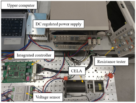
Experimental setup.
The preliminary parameters of CELA
Figures 3 and 4 show the excitation sources of the two operating modes under typical working conditions, respectively. (Typical working condition: movement stroke of 8 mm, valve opening duration of 20 ms). The transition time (5%–95% of the time taken up by the maximum stroke) of the motion of the actuator in the two operating modes is different, which is 6.9 ms in the single drive mode and 4.8 ms in the cooperative drive mode [16].
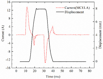
Typical valve lift and excitation current in single drive mode.
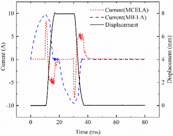
Typical valve lift and excitation current in cooperative drive mode.
In the simulation model, the soft magnetic material used in CELA is 1008 steel, which has high permeability and low cost. The permanent magnet material of two actuators is NdFeB-N45SH with excellent performance, and the coil bracket of two actuators is engineering plastic with light weight and high strength, which reduces the mass of the support and reduces the impact on the response speed, thus ensuring the strength and life of the actuator, and reduces eddy current loss. The coils of the two actuators are made of copper core enamelled wire.
The main structural and electrical parameters of the actuator are shown in Table 1. Figure 5 shows the finite element model, cloud and vector graphics of static magnetic flux density of CELA. To make the simulation results more realistic, the current and displacement curves obtained from previous experiments in different modes were used as excitation conditions.

FE model and cloud and vector graphics of static magnetic flux density of CELA.
The two operating modes are analyzed respectively under typical conditions of maximum stroke of 8 mm and valve opening duration of 20 ms. Table 2 illustrates the loss distribution of CELA. Coils and soft magnetic materials where the electromagnetic field changes drastically are regions of high loss density distribution.
Loss distribution of CELA
Loss distribution of CELA
In single drive mode, the total loss in one cycle is about 3.39 J, with copper loss accounting for about 43.36% of the total. Iron loss accounts for about 34.51% of the total loss, which is relatively lower than copper loss, and eddy current loss accounts for the largest proportion. Figure 6 shows the vector diagram of eddy current density in single drive mode. Eddy current loss is concentrated primarily near the inner yoke and end cover, which is likewise connected to the distribution of permanent magnet. Strong eddy currents are generated by the inner yoke and end cover in the circumferential direction, and the density grows steadily in the radial direction. Furthermore, mechanical losses account for the smallest proportion, about 22.12%, which is due to the direct-drive mode.
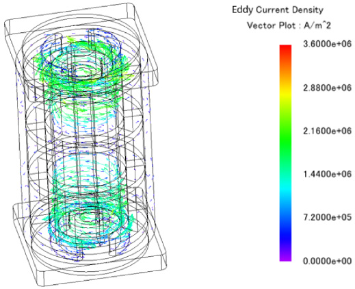
Vector diagram of eddy current density in single drive mode.
In the cooperative drive mode, the total loss in one cycle is 11.71 J, with copper loss accounting for 40.48%, iron loss accounting for 51.15%, and mechanical loss accounting for 8.37%. The specific loss distribution in cooperative drive mode is shown in Table 2. The copper loss and iron loss of MCELA are 0.59 J and 0.46 J, respectively. The loss distribution of MCELA is similar to that of single drive mode, but much smaller than that of single drive mode. For MIELA, the copper loss is 4.15 J and the iron loss is 5.53 J. As can be seen from the current curve in Fig. 4, the MIELA needs a longer continuous power time, so the loss is higher. Figure 7 shows the vector diagram of eddy current density in cooperative drive mode. For MCELA, eddy current loss is concentrated primarily near the inner yoke and end cover. The high density of eddy current loss is mainly distributed at the armature and the magnetic guide ring for MIELA. Due to the difference in structure and principle, the loss distribution of MIELA is quite different from that of MCELA, and its iron loss ratio is higher. It is worth to further study the variation of iron loss.
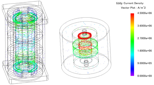
Vector diagram of eddy current density in cooperative drive mode.
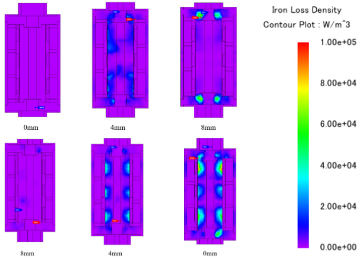
Cloud map of iron loss density of the opening and closing process of MCELA in cooperative drive mode under typical working condition.
Analysis was conducted in the cooperative drive mode in which both MCELA and MIELA are powered on. Figures 8 and 9 are the cloud map of iron loss density of the opening and closing process of MCELA and MIELA in cooperative drive mode under typical working condition, respectively. First of all, for both MCELA and MIELA, the change rule of iron loss is the same in the opening process and closing process, which increases with the increase of the displacement of moving parts, and the iron loss density of MIELA is significantly higher than that of MCELA, which is consistent with the previous analysis. Secondly, with the movement of the moving parts, the iron loss distribution of the MCELA is always symmetrical up and down, and this is because its magnetic field distribution has no obvious change. In contrast, MIELA is based on the principle of minimum magnetoresistance in the magnetic circuit, its electromagnetic field changes obviously in the working process, and the controllable electromagnetic force generated by the excitation current enhances the magnetic flux at one end of the armature while weakens the magnetic flux at the other end of the armature. When the excitation current is too large, the magnetic saturation of the magnetic guide ring and armature is serious, which is also the reason for the high iron loss of MIELA.
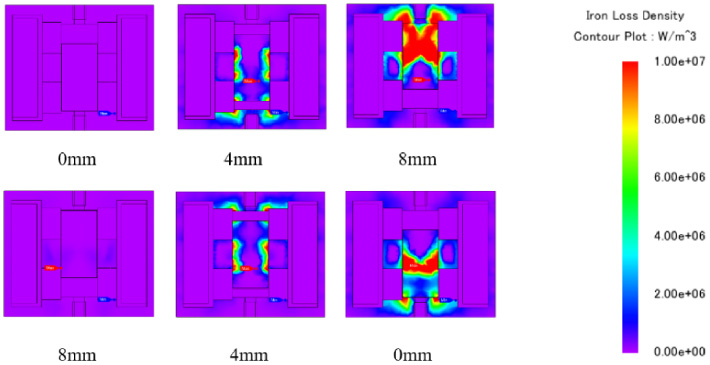
Cloud map of iron loss density of the opening and closing process of MIELA in cooperative drive mode under typical working condition.
Losses under the variable stroke
Maximum valve lift of the CELA can be regulated by adjusting the target value in the control program. The CELA’s losses were calculated and analyzed under three different valve stroke conditions of 4 mm, 6 mm and 8 mm.
In single drive mode, copper loss, iron loss and mechanical loss of CELA increase with the increase of valve stroke, as shown in Fig. 10(a). At 8 mm valve stroke, the total loss per cycle was 3.39 J, an increase of about 50.67% compared to 2.25 J at stroke of 6 mm. The loss of copper and iron increased by about 50.00% and 34.48%, respectively. The total loss per cycle increased by about 76.56% in 8 mm stroke compared to 1.92 J at stroke of 4 mm. Copper loss and iron loss increased by 75.00% and 77.27%, respectively.
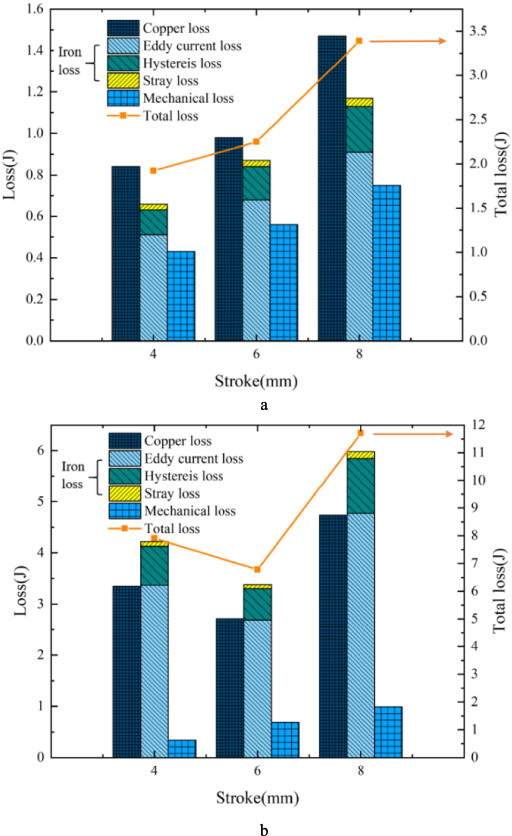
Loss distribution of CELA under variable stroke. (a) Loss compositions in single drive mode, (b) loss compositions in cooperative drive mode.
In the cooperative drive mode, as shown in Fig. 10(b) and Table 3, with the increase of valve stroke, the loss changes are different from that in the single drive mode, the loss at stroke of 8 mm was greater than that at stroke of 6 mm, and the loss at stroke of 4 mm was also greater than 6 mm. The main reason was that at the stroke of 4 mm, the MIELA was at the midpoint of the stroke and has no self-holding capacity, so the MCELA needed to be energized to provide a certain holding force. At the stroke of 8 mm, CELA’s total loss per cycle was 11.71 J, which was increased by 72.97% compared to 6.77 J at the stroke of 6 mm. Copper loss and iron loss increased by 74.91% and 77.22%, respectively. Among them, the copper loss of MCELA increased by 40.48% and the iron loss increased by 39.39%. The copper loss of MIELA increased by 81.22% and the iron loss increased by 81.31%. CELA’s total loss per cycle increased by approximately 48.04% at the stroke of 8 mm compared to 7.91 J at the stroke of 4 mm. Copper loss increased by about 41.49% and iron loss by 41.94%. Among them, the copper loss of MCELA increased by 34.09% and the iron loss increased by 31.43%. The copper loss of MIELA increased by 42.61% and the iron loss increased by 42.89%.
Loss distribution under variable stroke in cooperative drive mode
In addition, it could be found that under the same operation mode, even if the stroke changed, the ratio of copper loss to iron loss remained almost constant, which was consistent with the change of different components of iron loss.
In the operation of solenoid driven valve mechanism, gas can be realized by controlling valve opening and closing and adjusting valve timing. This can not only change the valve timing, but also change the valve opening duration. In the future study of engine thermodynamics, the adjustment of valve timing and opening duration is vital to the improvement of engine performance. The CELA’s loss was calculated and analyzed under three different valve opening duration of 20 ms, 25 ms and 30 ms.
In single drive mode, copper loss, iron loss and mechanical loss increased slightly as the valve opening time increased, as shown in Fig. 11(a). When the valve opening duration was 30 ms, the total loss per cycle increased by 0.59% compared with 25 ms. Both the copper loss and iron loss increased by approximately 0.39%. When the valve opening duration was 30 ms, the total loss per cycle increased by 0.88% compared with 20 ms. The copper loss increased by 1.51% and iron loss by 1.50%.
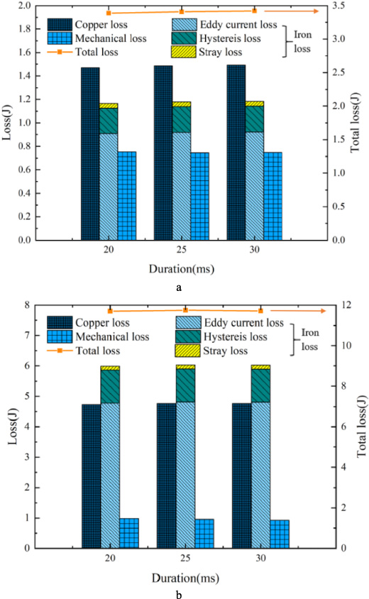
Loss distribution of CELA under variable valve opening duration. (a) Loss compositions in single drive mode, (b) loss compositions in cooperative drive mode.
In the cooperative drive mode, the changes of copper loss, iron loss and mechanical loss were insignificant, as shown in Fig. 11(b). When the valve opening duration was 30 ms, the CELA’s total loss per cycle decreased by only 0.27% compared with 25 ms. The copper loss increased by about 0.05% and the iron loss decreased by 0.09%. When the valve opening duration was 30 ms, the CELA’s total loss per cycle increased by 0.13% compared with 20 ms. The copper loss increased by 0.67% and iron loss by 0.60%.
When the valve opening duration was changed, the total loss of a cycle did not change significantly, implying that the change in valve opening duration had little effect on the loss. Furthermore, as shown in Figs. 11(a) and 11(b), the ratio of copper loss to iron loss, as well as the ratio of each component of iron loss, remained consistent.
In this paper, the loss variation law of a novel compound electromagnetic linear actuator under two different operating modes (single drive mode and cooperative drive mode) was investigated. Through simulation and test, the influence of stroke and valve opening duration on the distribution and variation of loss was analyzed. The conclusions are drawn as follow: The compound actuator proposed has a higher driving force output and faster transition time in cooperative drive mode, with a higher energy loss of 11.71 J/cycle, 2.45 times increase in typical operating conditions compared to single drive mode, which is due to the longer continuous power-on time required by the MIELA. Due to the different structure and working principle, the proportion of energy loss component of MCELA and MIELA are quite different in the working process. Among them, the ratio of copper loss to iron loss of MCELA is about 5:4, and that of MIELA is about 3:4. Regarding the forms of iron loss, eddy current loss accounts for more than 76%, which is mainly concentrated on the inner yoke, end cover, armature, magnetic guide ring and other components. The increase in working stroke in single drive mode raises energy loss. The energy loss decreases initially and then rises as the stroke grows in the cooperative drive mode. When the stroke is maximum in both operating modes, the loss is the largest. The valve opening duration has little effect on loss.
The above work reveals the loss variation rule of the novel compound electromagnetic linear actuator under various working modes, which lays a foundation for the research on the loss reduction and heat dissipation of the compound electromagnetic linear actuator.
Footnotes
Acknowledgement
This work was supported by the National Natural Science Foundation of China [Grant No. 52205271].