
Abstract
In order to solve the problem that the design of high-speed permanent magnet motor (HSPMM) is constrained by multi-physical fields, this paper starts with the comprehensive study of multi physical fields, introduces the finite element calculation model of rotor strength-rotor dynamics-electromagnetic field-fluid field and temperature field, carries out the comprehensive design of a 100 kW, 18 000 r/min FeCo based HSPMM, and gives the detailed and complete research process of the main parameters of HSPMM under multi-physical field constraints. First, the initial dimensions of the motor are obtained by electromagnetic and mechanical design theory. Secondly, the influence of design parameters on rotor stress is analyzed in detail, including the influence of bearing rigidity, impeller mass, rotor diameter, rotor core length and gyroscopic effect on critical speed. Subsequently, the electromagnetic characteristics of the motor are comprehensively studied, the cooling system is designed in the Flow-Heat coupling calculation model and the temperature field is studied. Finally, the prototype test verifies the correctness and validity of the comprehensive research method of multi physical field.
Keywords
Introduction
With the advantages of high efficiency, small size and fast dynamic response, HSPMM has been widely used in high-speed compressor, waste heat power generation, flywheel energy storage and other industries [1–3]. In order to achieve high efficiency at high speed, the design of HSPMM is constrained by multiple physical fields, including rotor mechanical stress, rotor dynamics, electromagnetic characteristics, power loss, wind friction loss and temperature rise characteristics.
As a new generation of rare earth permanent magnets (PMs), the new FeCo based PM material has lower temperature coefficient under the condition of meeting certain coercivity, and can adapt to the application under more complex ambient temperature and more difficult heat dissipation conditions, that is, it has the advantages of high magnetic energy product and high coercivity in electromagnetic properties; Among them, the maximum magnetic energy product of NdFeB rare earth PM material can reach more than 54 MGOe, but its Curie temperature is relatively low, generally not more than 360 °C, the temperature stability is relatively poor (the remanence temperature coefficient is between −0.09 and −0.12%/°C), and it is easy to oxidize and corrode, which limits the improvement of the current performance of new energy motors; Although the samarium cobalt rare earth PM material has good temperature stability and corrosion resistance, its application in the motor market is greatly limited due to the magnetic energy product is only about 30 MGOe, and it is fragile and difficult to process.
FeCo based rare earth permanent magnetic materials are new materials, which have high magnetic energy product, good temperature stability and corrosion resistance, meet special application requirements, and fill the performance gap between NdFeB PMs and SmCo PMs; At the same time, the PM material has high comprehensive magnetic properties at room temperature, good remanence temperature coefficient and coercivity temperature coefficient, and excellent corrosion resistance. Its Curie temperature is 360–550 °C, Excellent temperature stability (remanence temperature coefficient: 20–100 °C is −0.09–−0.001%/°C; intrinsic coercivity temperature coefficient: 20–100 °C is −0.55–−0.35% °C) and good corrosion resistance (weight loss of less than 1mg/cm2 in 144 hours under 120 °C, 2 atm, 100% RH test environment), providing conditions for the research and development of new energy drive motors that meet the operation requirements of complex environment; The performance comparison curve of FeCo based PM material and NdFeB PM material is shown in Fig. 1.
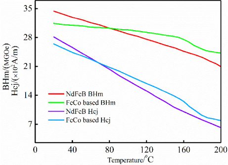
Comparison of properties between FeCo based PM and NdFeB PM.
The new FeCo based HSPMM design should consider not only the electromagnetic characteristics at high speed and high frequency, but also the mechanical stress and dynamic characteristics of the high-speed rotor. Unreasonable rotor mechanical design will lead to motor damage [4–6]. Due to the high frequency and high speed of the motor, the performance and structure of PM materials are affected by various factors, including rotor mechanical stress and dynamics, electromagnetic field distribution and power loss, as well as high temperature related to material structure [7]. At the beginning of the design of the new FeCo based HSPMM, in order to improve the mechanical strength of the high speed rotor, a relatively small rotor diameter is usually selected [8]. However, according to the theory of motor design, in order to meet the power demand, the small rotor diameter will inevitably lead to a relatively long iron core length, which may reduce the critical speed of the HSPMM rotor [9,10]. When the motor running speed is close to the critical speed, the motor will resonate [11], The rotor of HSPMM is deformed or even damaged [12], and the safe operation of the motor cannot be guaranteed. Therefore, it is very important to determine the rotor length and diameter through comprehensive design research to avoid rotor resonance [13]. In [14–16],the authors has built-in NdFeB PM in the HSPMM, and titanium alloy sleeve is used outside the PM to ensure the safety of the motor at high speed. Compared with the alloy steel sleeve, the carbon fiber sleeve has been proved to be a better choice, because of its low conductivity, so the eddy current loss is low [17]. Although the thick sleeve can effectively improve the strength of the rotor, thereby improving the reliability of high-speed operation of the motor [18], the thicker sleeve leads to a larger air magnetic resistance, and the larger air gap magnetic resistance requires the use of thicker PM materials to maintain the air gap magnetic flux density, so as to maintain the output torque and power. On the other hand, the poor thermal conductivity of carbon fiber sleeve will worsen the rotor cooling conditions [19], which may lead to rotor overheating and irreversible demagnetization of PM at high temperature [20]. Because the temperature expansion coefficient of NdFeB PM is relatively small, the stress of rotor system changes more obviously with the increase of rotor temperature [21]. At the same time, the temperature rise of HSPMM is mainly determined by the power loss and the effectiveness of the cooling system [22]. In [23,24],the author analyzed the objective optimization of electromagnetic field and stress field on the rotor system of HSPMM, and rotor dynamics was simply verified in the design of multiple physical fields. To sum up, the design of HSPMM involves the design of multiple physical fields such as electromagnetic field, stress field, rotor dynamics and temperature field [25]. The influence of the key parameter design of the motor on the multi physical field performance of the HSPMM has not been studied in detail, including the influence of the PM material, the axial length of the iron core, the rotor diameter and the thickness of the PM on the rotor stress distribution, as well as the influence of the impeller quality, the bearing support stiffness and the rotor design parameters on the critical speed of the rotor. At the same time, the temperature stress coupling relationship is also ignored in the multi physical design, The existing multi physical field analysis and research work lacks a complete and detailed HSPMM multi physical field integrated design process.
Based on the above research status of HSPMM, this paper proposes a complete multi physical field integrated design process of HSPMM, in order to obtain the design parameters of HSPMM. First, the preliminary design parameters are obtained through the electromagnetic and rotor stress design theory. Then, the influence of design parameters on rotor stress is analyzed in detail, including permanent magnet material, sleeve thickness, permanent magnet thickness, rotor temperature, and rotor diameter. In addition, the rotor dynamics is analyzed in detail, including the influence of bearing stiffness, rotor diameter, impeller mass, axial length of iron core and gyroscopic effect on the critical speed. Through the analysis of rotor stress and rotor dynamics, the main parameters of high speed rotor are further determined. Based on the above parameters, the electromagnetic field and loss characteristics of HSPMM are comprehensively studied in order to obtain good electromagnetic performance. Then, according to the flow thermal coupling finite element calculation model, the cooling system is designed, the motor temperature field is studied, and the temperature stress coupling finite element calculation model is established, In order to obtain more accurate results, finally, based on the above comprehensive design parameters, a 100 kW, 18000 r/min FeCo based HSPMM is manufactured. The test results show that the complete and detailed multi physical comprehensive research process is feasible.
FeCo based is a new type of permanent magnet material, which has lower temperature coefficient and higher thermal expansion coefficient than NdFeB PM material. It has great theoretical significance and engineering practical value in the design and application of HSPMM.
In order to realize the application exploration of FeCo based in the design of HSPMM, taking NdFeB HSPMM with rated power of 100 kW and rated speed of 18000rpm as an example, the structural parameters of the new iron-cobalt base high-speed permanent magnet motor are designed and studied by adopting the geometric similarity law and the co-punching design; At the same time, considering that the structural design of the new FeCo based PM motor is limited by electromagnetic, mechanical, temperature rise and other factors, the initial design of the new FeCo based PM motor needs to judge whether the motor parameters are optimal from the perspective of multiple physical fields. Therefore, a comprehensive optimization design method of the motor based on the multi-physical field coupling algorithm and the motor design principle is proposed. The specific motor structural design process is shown in Fig. 2.
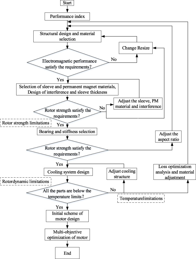
Comprehensive design method of multi physical fields for new FeCo based HSPMM.
The determination of key parameters of HSPMM is the first step of electromagnetic design. The comprehensive design of multiple physical fields is carried out with a new FeCo based HSPMM of 100 kW and 18000 rpm/min. The determination of key parameters of the motor is introduced in detail. For the HSPMM, the tensile strength of the rotor material should be greater than the rotor stress [24]:
The maximum linear speed 𝜐max on the outer surface of the rotor is:
Sleeve material performance parameters
For the HSPMM, the rotor sleeve is often made of stainless steel, alloy steel, titanium alloy and carbon fiber materials. The material properties are shown in Table 1. Steel accounts for 96% of the rotor weight. Therefore, the rotor density is set at 7850 kg/m3. The maximum tensile strength of stainless steel, alloy steel, titanium alloy and carbon fiber are 520 MPa, 750 MPa, 865 MPa and 1500 MPa respectively.

Maximum diameter of rotor at different speeds of sleeve materials.
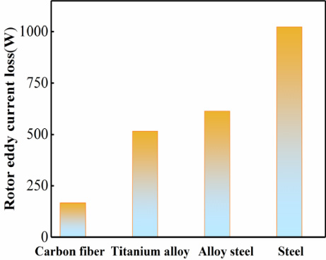
Rotor eddy current loss of different sleeve materials.
Through Eqs (1), (2) and (3), the relationship between the maximum rotor diameter of different sleeve materials and the rotor speed is obtained, as shown in Fig. 3. From the figure, it can be seen that for carbon fiber sleeve, the rotor diameter can be designed to be the largest, while for stainless steel sleeve, the rotor diameter can be designed to be the smallest. In addition, based on the same design scheme, four sleeve materials with the same thickness are used, The analysis of their rotor eddy current loss is shown in Fig. 4. For the high-frequency and high-speed condition of HSPMM, due to the relatively large conductivity of titanium alloy and stainless steel, there will be huge rotor eddy current loss, which will not only greatly reduce the efficiency of the motor, but also bring great difficulties to the rotor’s heat dissipation band. Due to the low conductivity of carbon fiber sleeve, the rotor eddy current loss is much smaller than the other three sleeves, However, the assembly process of carbon fiber sleeve is complex and the heat dissipation is difficult. Therefore, for the specific HSPMM, we should comprehensively consider which kind of sleeve to choose. In this paper, the carbon fiber sleeve is selected, and the diameter of the large rotor can effectively reduce the axial length of the rotor and increase the dynamic characteristics of the rotor. However, the finite element simulation shows that the diameter of the large rotor will greatly increase the eddy current loss and air friction loss of the rotor.
Therefore, the selection of rotor diameter must consider the balance of rotor dynamics, rotor stress and rotor loss. For the new FeCo based HSPMM designed in this paper, considering the safety of the rotor, the maximum linear speed on the outer surface of the rotor 𝜐max is limited to about 110 m/s, and the initial value of rotor diameter is set at 130 mm.
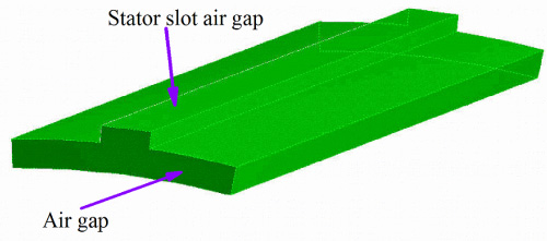
Calculation model for friction loss of air gap CFD.
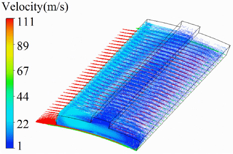
Air gap fluid velocity distribution.
After determining the outer diameter of the new FeCo based HSPMM rotor, due to the friction between the surface of the HSPMM rotor and the air, the air friction loss increases significantly with the increase of the motor speed. The air gap friction loss can be calculated by the following analytical equation:
Although the calculation results of the friction loss of the air gap fluid can be quickly obtained by the analytical method, the calculation results cannot be accurate due to the calculation formula of the empirical coefficient. In order to calculate the resistance loss of the air gap fluid more accurately, the finite element computational fluid dynamics is used. Figure 5 shows the calculation model of the friction loss of the air gap fluid, and Fig. 6 shows the velocity of the air gap fluid, Fig. 7 shows the relationship between air gap fluid resistance loss and rotor axial length under different rotor diameters, and Fig. 8 shows the relationship between air gap fluid resistance loss and rotating speed under different rough heights. Finally, it is determined that the air gap thickness is 2 mm and the rotor axial length is 95 mm.
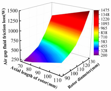
Change of air gap fluid resistance loss with rotor diameter and axial length.
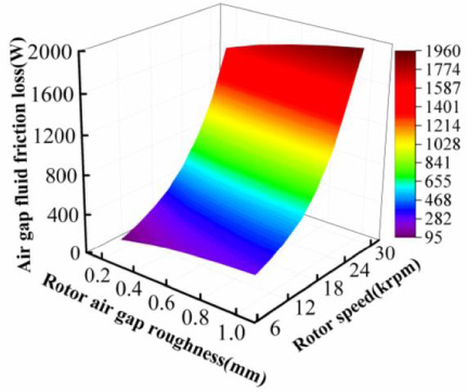
Change of air gap fluid resistance loss with rotor speed and air gap roughness.
According to the above comprehensive analysis, the main design parameters of the new FeCo based HSPMM are shown in Table 2, and the motor structure is shown in Fig. 9.

Novel FeCo based HSPMM structure.
Main parameters of HSPMM
Analysis of rotor stress
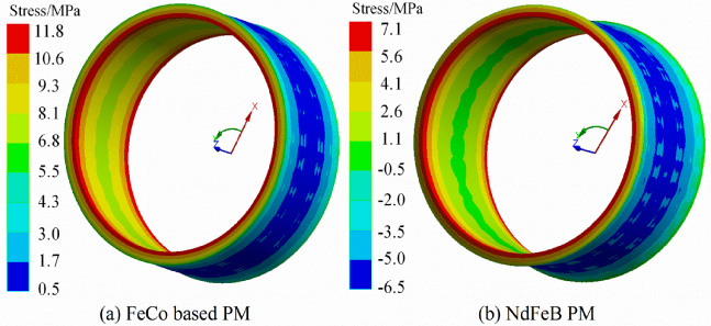
After the preliminary determination of the key parameters of HSPMM, the stress of the rotor system should be analyzed in detail first, in order to further determine the rotor diameter, PM material and sleeve thickness. In the stress analysis, the new FeCo based PM material is used for performance comparison with NdFeB PM material. The material properties are shown in Table 3. In order to ensure the safety of the rotor when running at high speed, the tangential stress of the sleeve and PM should be less than its maximum allowable tensile strength. The constraint condition of the rotor stress at 1.2 times the rated speed is that the tensile stress of the new FeCo based PM should be less than 70 Mpa, and the tensile stress of the NdFeB PM should be less than 80 MPa, The tensile stress of carbon fiber sleeve should be less than 1500 MPa. It is well known that the rotor temperature has a great influence on the rotor stress distribution. When calculating the rotor stress, it is assumed that the rotor temperature is 110 °C, and the interference between the sleeve and the PM is 0.08 mm.
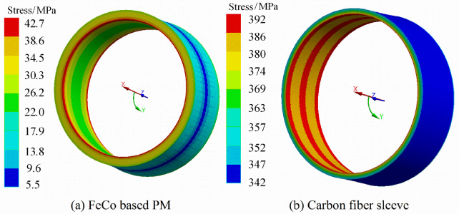
Stress of FeCo based PM and NdFeB PM under static condition.
Rotor material performance parameters
The stress distribution of the rotor under FeCo based and NdFeB PM materials can be obtained through 3D finite element analysis, as shown in Figs 10, 11 and 12. It can be seen that the tensile stress of the sleeve under the two PM materials is far lower than the maximum tensile strength of carbon fiber. However, the tensile stress of NdFeB PM exceeds the maximum tensile strength of the PM itself at 21600 r/min and 110 °C, The tensile stress of FeCo based PM is 42.7 MPa at 21600 r/min and 110 °C, which is far lower than the maximum tensile strength of FeCo based PM of 70 MPa.
Stress distribution of FeCo based PM and sleeve stress under hot rotating condition.
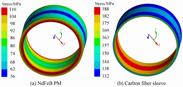
Stress distribution of NdFeB PM and sleeve stress under hot rotating condition.
Under the two kinds of PM materials, the change of the stress of the sleeve and PM with the working temperature is shown in Fig. 13. It can be seen that with the increase of the working temperature of the rotor system, the stress of the sleeve and PM increases sharply. When the temperature reaches about 95 °C, the tensile stress of the NdFeB PM has exceeded 80 MPa, which has exceeded its maximum tensile stress tensile strength, and cannot meet the strength requirements of the high-speed rotor, Because the temperature expansion coefficient of the new FeCo based PM is much larger than that of the NdFeB PM, and the influence of the rotor system operating temperature on the stress of the new FeCo based PM is much smaller than that of the NdFeB PM, in the design of HSPMM, in order to improve the stress of the rotor at high temperature, FeCo based PM material with large temperature expansion coefficient should be used, That is, considering that the thermal expansion coefficient of FeCo based PM is large, the effect of rotor temperature on the stress of FeCo based PM is far less than that on the stress of NdFeB PM, and the PM material with large thermal expansion coefficient should be used for high-speed motor.
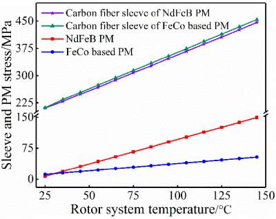
The change of rotor stress with temperature under two kinds of PM materials.
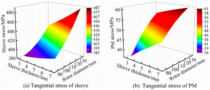
The change curve of rotor stress with sleeve thickness and rotor diameter. (a) Sleeve stress. (b) PM stress.

The change curve of the stress with the thickness of the sleeve and the thickness of the PM. (a) Sleeve stress. (b) PM stress.
The rotor stress under the same rotor diameter is analyzed by 3D finite element method with the sleeve thickness and PM thickness, as shown in Fig. 14. In the rotor stress analysis, the influence of PM on the rotor stress is very small, and the influence of PM on the rotor stress can be ignored. Although the corresponding requirements of sleeve stress can be easily met, the requirements of PM stress are difficult to meet. In order to meet the rotor stress, The variation of rotor stress with rotor diameter and sleeve thickness is also studied in detail. As shown in Fig. 15, the influence on sleeve stress and rotor diameter is much greater than the thickness of sleeve. However, it has a significant influence on the stress of PM, sleeve thickness and rotor diameter. When the maximum sleeve thickness is kept at 5 mm, the rotor diameter should be less than 120 mm, which can meet the requirements of rotor stress.
When the rotor speed approaches its critical speed, the rotor will resonate and be seriously deformed and damaged. Rotor dynamics is affected by the length of iron core, rotor diameter, bearing stiffness, distribution of rotor mass and gyroscopic effect. In order to avoid high-speed damage of rotor, the maximum speed n of motor rotor should be limited [25]:

The 3D FEA calculation model of rotor critical speed.
For the HSPMM designed in this paper, the maximum speed is 20000 r/min. According to formula (3), the critical speed of the rotor should be higher than 28571.4 r/min. A 3D finite element model with impeller is established to calculate and analyze the critical speed of the rotor system, as shown in Fig. 16.
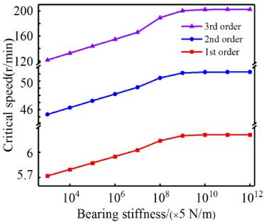
Relationship between critical speed and bearing stiffness.
In the three-dimensional finite element analysis (FEA), when setting the rated speed of HSPMM, the gyroscopic effect caused by rotor rotation has been considered, and the influence of bearing support stiffness on the critical speed within the range of 103–1012 N/m has been analyzed. As shown in Fig. 17, with the increase of bearing stiffness, the critical speed of first order mode and second order mode increases sharply. When the support stiffness is greater than 108 N/m, the first order and second order modes tend to be stable, but at this time, The critical speed of the third order mode will increase sharply, so the bearing stiffness has a high impact on the critical speed. In order to avoid resonance of the rotor, appropriate bearing support stiffness should be designed. In addition, in order to analyze the influence of impeller mass on the critical speed of rotor, equal mass equivalence is adopted for the impeller, as shown in Fig. 18. With the increase of impeller mass, the critical speed of rotor gradually decreases, and then tends to be stable. Therefore, appropriate impeller mass distribution is also crucial to the design of rotor dynamics.
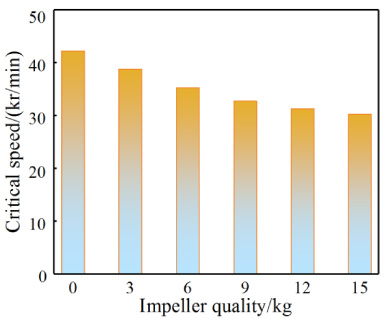
Relationship between critical speed and impeller mass.
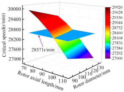
The first critical speed varies with the diameter and length of the rotor.
Figure 19 shows the relationship between the rotor critical speed and the rotor diameter and core length. The influence of the rotor core length on the critical speed is more significant than that of the rotor diameter. It can be seen that the larger the rotor diameter, the smaller the iron core length to meet the requirements of critical speed. According to the previous analysis of rotor stress, the maximum rotor diameter is limited to 120 mm. Therefore, under the limitation of the maximum rotor diameter, the required core length is 80 mm.
On the basis of the above-mentioned HSPMM comprehensive design analysis, the design of rotor outer diameter and iron core length is parameterized, and the detailed design scheme of the new FeCo based HSPMM is further determined according to the analysis of HSPMM electromagnetic characteristics and loss efficiency. In the finite element analysis, given that the thickness of FeCo based PM is 9 mm and the number of conductors per slot is 6, the results of the finite element analysis are shown in Table 4. The stator core is made of 0.5 mm silicon steel sheets, carbon fiber sleeve, The electrical conductivities of the new FeCo based PM and rotor core are 1.5 × 10⁵ S/m, 1.25 × 10⁶ S/m and 2 × 10⁶ S/m, respectively. Meanwhile, the air friction loss can be obtained from the previous air gap fluid friction loss calculation model. It can be seen from Table 4 that with the increase of the rotor diameter, the air gap friction loss and rotor eddy current loss gradually increase, especially the air gap friction loss shows a geometric increase, and the efficiency gradually decreases. Therefore, the smaller rotor diameter can reduce the air gap friction loss and rotor eddy current loss, and improve the working efficiency of the motor.
Influence of rotor diameter on electromagnetic performance
Influence of rotor diameter on electromagnetic performance
Table 5 shows the electromagnetic properties of FeCo based PM HSPMM with different thicknesses. In the finite element analysis, the diameter of the given rotor is 118 mm, and the number of conductors per slot is set to 6. As shown in Table 5, the smaller FeCo In order to achieve the output power of 100 kw based on PM thickness, the thickness of the rotor core must be increased, but the thickness of the rotor core can greatly affect the dynamic performance of the rotor. If the FeCo based PM is too thin, the required core length may be larger than the critical speed limit. It will lead to the rotordynamic critical speed resonance failure. Therefore, the appropriate FeCo based PM thickness should be comprehensively selected by balancing the electromagnetic characteristics and rotor dynamics.
Since the new FeCo based HSPMM adopts double-layer distributed short-distance winding, the number of conductors per slot must be an even number, i.e. 2, 4, 6 or 8, Table 6 shows the relationship between the electromagnetic performance of HSPMM and the number of conductors per slot, In the finite element analysis, the given rotor diameter is set to 118 mm and the FeCo based PM thickness is set to 9 mm. As can be seen from Table 6, when the number of conductors per slot is 4, in order to achieve the rated output power of 100 kW, the required iron core length is 110 mm. Through the previous rotor dynamics analysis, this will cause the rotor system to resonate. When each slot When the number of conductors is 8, it is obvious from Table 6 that the length of the rotor core can be reduced, but at the same time the current density reaches 7.28 A/mm2, but this will lead to a larger thermal load and high temperature.
Effect of permanent magnet thickness on electromagnetic properties
Influence of the number of conductors per slot on electromagnetic properties
On the basis of comprehensive consideration of electromagnetic characteristics, rotor stress and rotor dynamics analysis, the electromagnetic design scheme of the new FeCo based HSPMM is finally determined. The specific parameters are shown in Table 7. The electromagnetic performance of the new FeCo based HSPMM is analyzed through two-dimensional finite element simulation calculation, as shown in Fig. 20. Figure 20(a) shows the two-dimensional magnetic flux density distribution of the motor. The effective value of the reverse induced electromotive force at no-load is 217V, as shown in Fig. 20(b), Fig. 20(c) shows the phase current waveform at full load. The effective value of the phase current is 169.8A, and the output torque is 53.3 N⋅m. As shown in Fig. 20(d), the efficiency of the motor can reach 95.5%.
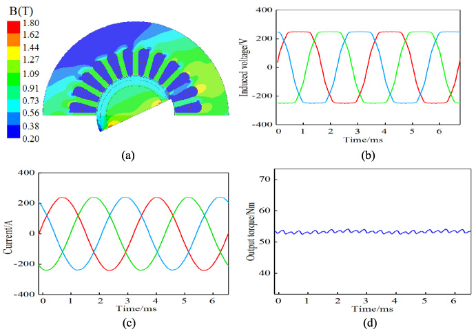
Electromagnetic characteristics of HSPMM. (a) Magnetic flux density cloud map. (b) Induced EMF at no load. (c) Rated load phase current. (d) Output touqre.
Final motor design parameters
Thermal analysis
For the new FeCo based HSPMM designed in this paper, thermal analysis is a very important part of the comprehensive design process of the motor. In order to ensure the safe operation of the new FeCo based HSPMM, the average working temperature of the winding and rotor is set to 120 °C, and the cooling path is set in the stator slot and stator housing to improve the heat transfer of the HSPMM. According to the symmetry, the half 3D model of the HSPMM is taken as the solution domain, A 3D flow heat coupling calculation model is established. The inlet velocity is set at 5 m/s and the inlet temperature is set at 32 °C. Because the rotor speed will affect the fluid flow, the sleeve, PM, rotor and shaft are set to rotate at the rated speed. Figure 21 shows the overall fluid speed distribution of the motor, and Fig. 22 shows the distribution of the calculated temperature. The maximum temperature of the stator winding is 118.2 °C, which occurs in the middle of the stator winding group, and the maximum temperature in the middle of the rotor is 103 °C.

Overall speed distribution of a new FeCo based motor.
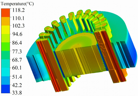
Overall temperature distribution of a new type of FeCo based motor.
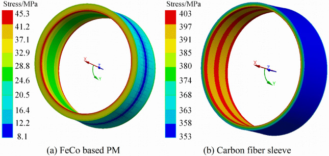
In the rotor stress analysis in the previous Section 3.1, due to the assumption that the rotor temperature is constant, there will be some large errors compared with the actual operation of the rotor. Therefore, it is necessary to use the temperature stress coupling calculation model to recalculate the rotor stress at 1.2 times the rated speed to obtain more accurate results. Figure 23 shows the rotor stress distribution obtained through the coupling analysis. The maximum stress of FeCo based PM is 45.3 MPa, The maximum stress of the sleeve is 403 MPa, which meets the tensile strength of the new FeCo based PM material, and a certain safety margin is reserved.
Overall temperature distribution of a new type of FeCo based motor.
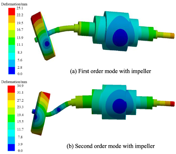
For FeCo based HSPMM whose specific parameters have been determined, the vibration mode and critical speed of the rotor must be checked through 3D finite element analysis. The mass of the impeller is 13.6 kg and the bearing stiffness of the bearing is 5 × 10⁷ N/m, Fig. 24 shows the first order modal shapes and the second order modal shapes. Considering the influence of gyroscopic effect on critical speed when the rotor rotates, Fig. 25 shows the Campbell diagram of the rotor system, which proves that the rotor will not resonate within the whole speed working range.
Vibration mode of rotor mode.
It can be seen from Fig. 24 that the maximum shape variable of the first mode is 25.1 mm, and the maximum shape variable of the second mode is 34.9 mm.
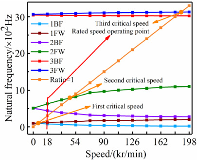
Campbell diagram.
According to the final size data of the above comprehensive research and design of multiple physical fields, a FeCo based HSPMM prototype with a rated power of 100 kW and a rated speed of 18000 r/min has been manufactured. Figure 26 shows the prototype being tested on the test bench.
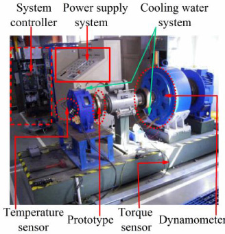
High speed permanent magnet motor test platform.
(1) The strength and dynamics experiments of the prototype rotor consider that the rotor PM adopts a new type of FeCo based PM material, and its outer surface is protected by a 5 mm thick sleeve. The power supply of the new FeCo based HSPMM is provided by a frequency converter. Under the no-load operation condition, displacement sensors are installed at the outer ends of the rotor bearing to test the vibration amplitude of the rotor system of the new FeCo based HSPMM at different speeds.
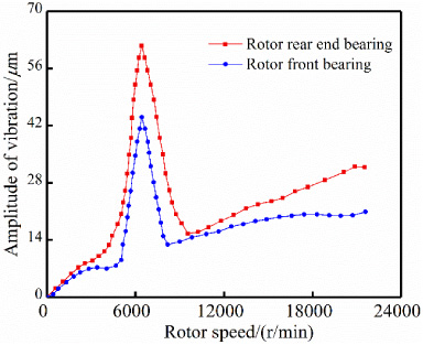
Vibration test experiment of FeCo based HSPMM at no load.
According to the rotor vibration test, when the speed of the prototype is lower than 3000 r/min, its amplitude is very small; Under the working condition of more than 3000 r/min, the rotor vibration displacement is proportional to the rotating speed; When the speed reaches 6500 r/min, the amplitude reaches the maximum value; The rotor vibration test results of the prototype at no-load are shown in Fig. 27. In the rotor structure system with impeller, its first critical speed is 6137.2 r/min, which is basically consistent with the test value of prototype experiment, which also indirectly explains the feasibility and applicability of the rotor dynamics analysis method in this paper
(2) Experimental verification of electromagnetic and temperature rise of prototype under rated load. The temperature distribution on the stator is measured. Specifically, the stator temperature is measured by four temperature sensors embedded in the stator slot winding.
After the prototype runs for 2 hours according to the rated working system, at this time, the displayed value of the temperature sensor tends to be constant, then it can be considered that the internal heat balance of the motor is reached at this time, that is, the constant temperature value. The measured stable temperature of the stator winding is 112.3 °C, which is consistent with the calculation results of the 3D finite element fluid temperature coupling model; At the same time, the output power of the motor is obtained by the power analyzer of the experimental platform, and the measured efficiency is 94.3%. The comparison of the key experimental measurement parameters and the calculated values of the multi-physical field comprehensive analysis is shown in Table 8. From Table 8, it can be seen that the experimental measured results are consistent with the results of the multi-physical field comprehensive analysis and calculation.
Electromagnetic and temperature performance at rated load
This paper presents a detailed and complete multi-physics integrated design process of HSPMM, including the initial design scheme of the motor, rotor stress, rotor dynamics, electromagnetic integrated characteristics and fluid temperature coupling characteristics. The finite element calculation values of the prototype and the experimental test results agree well, which confirms the correctness and effectiveness of the integrated design process of the motor. The summary is as follows: Based on the multi-physics coupling algorithm and the motor design principle, a comprehensive design method for the new FeCo based HSPMM is proposed. This method can consider the coupling effect of multi-physics fields in the design of the new FeCo based HSPMM; According to the research on the rotor strength of FeCo based PM motor, due to the large thermal expansion coefficient of the new FeCo based PM, the effect of rotor temperature on the stress of FeCo based PM is far less than that of NdFeB PM. The FeCo based PM material with large thermal expansion coefficient should be used for HSPMM, and it is pointed out that the FeCo based PM rotor has advantages in strength; According to the study of temperature stress of FeCo based PM motor, larger rotor diameter will lead to larger rotor eddy current loss and reduce the efficiency of FeCo based HSPMM. Placing more conductors in each slot can greatly reduce the length of iron core, and also greatly increase the thermal load of FeCo based HSPMM. In addition, increasing the thickness of FeCo based PM can also effectively reduce the core length. According to the rotor dynamics research of FeCo based PM motor, the influence of rotor core length on critical speed is more significant than that of rotor diameter; For the new type of FeCo based high-speed rotor with impeller, the natural frequency of the first bending mode is 212 Hz, the critical speed is 12720 r/min, the natural frequency of the second mode is 432 Hz, and the critical speed is 25920 r/min; When the support stiffness k
c
of the bearing is lower than 5 × 10⁷ N/m, the rotor is a rigid rotor; When the support stiffness k
c
of the bearing is 5 × 10⁸ N/m, the rotor is a flexible rotor.