
Abstract
Due to the deficiency in using the cross-bonded grounding mode, a large circulating current is usually induced in the metal sheaths and armors, reducing the permissible current rating of submarine cables. To address this issue, this paper proposes a novel grounding mode to suppress these circulating currents and enhance the permissible current rating within the voltage limits of metal sheaths and armors. To achieve the best performance of the novel grounding mode, the optimal grounding impedances are given. Theoretical analyses indicate that for general submarine cables, the novel grounding mode can suppress the circulating currents within the voltage limits compared with the two-ends grounding mode, and can reduce the short-circuit terminal voltage of metal sheaths and armors compared with the non-interlinked version of the proposed mode. The numerical results further validate the better comprehensive performances of the novel grounding mode in reducing the power loss and short-circuit overvoltage.
Introduction
The ever-increasing demand for marine energy has paved the way for extensive usage of submarine cable transmission lines. For a given voltage level, the power transmission capacity is closely related to the current rating of the cables. Consequently, the current rating enhancing of submarine cables becomes necessary [1,2]. The current rating of a submarine cable is mostly determined by the allowable maximum temperature of the insulation dielectrics. The Joule losses in the central conductors, metal sheaths and armors are the major heat sources. In this regard, reducing the losses in the metal sheaths and armors is a feasible approach to enhance the current rating of a submarine cable.
The circulating current and its Joule losses in the metal sheaths and armors are significantly affected by the cable grounding mode. Hitherto, the mostly used grounding modes include three types: the two-ends grounding mode, the multi-spots grounding mode and the whole-line grounding mode. Compared to the two-ends grounding mode, the multi-spots and the whole-line grounding modes can both effectively reduce the capacitive circulating current [3–5], but they can not suppress the inductive component of the circulating current. Moreover, for the not too long submarine cable lines (e.g. the cable line of about 30 km), the three typical grounding modes will all result in a considerable circulating current and losses in the metal sheaths and armors, and they have no significant differences on increasing the cable current rating [6]. Some literatures report that increasing the grounding impedance of metal sheaths can markedly reduce the circulating currents, but will make the sheath voltage rise, even to an unsafe value [7–9]. The cross-bonded grounding mode can effectively suppress the circulating current in metal sheaths [10,11], but is infeasible to be applied in submarine cables, due to its damage to the waterproofness of the cable insulation.
To suppress the circulating currents and reduce the losses, this paper proposes a novel grounding mode for submarine cable lines. By bonding the metal sheaths or armors in a special fashion at the terminals and applying appropriate grounding impedance, the proposed novel grounding mode can enhance the current rating, reduce the risk of high-voltage flashover, and be power saving.
The novel grounding mode
Configuration of the novel grounding mode
The configuration of the proposed novel grounding mode for a submarine cable system is shown in Fig. 1. It requires to bond the metal sheaths or armors only at terminal ports. Both A-phase cable and C-phase cable have one end directly grounded, with the other end bonded to B-phase cable. To limit the induced voltage, the interlinked ends of cables are grounded through an impedance. For waterproof and easy-to-install purposes, coaxial cables are used to connect the metal sheaths and armors to the grounding box. The red lines in Fig. 1 refer to the inner conductor of the coaxial cable, and the blue lines refer to the outer conductor.
The non-interlinked version of the proposed novel grounding mode, as is shown in Fig. 2, is easier to implement in engineering. It will degrade the circulating current under normal operating conditions, but can induce a high overvoltage at the terminal when a grounded fault occurs in this phase cable. The existing three typical grounding modes all ensure that the induced terminal voltage is close to zero, but will induce considerable circulating currents, as explained in Section 1. However, the proposed novel grounding mode combines the advantages of the grounding mode in Fig. 2 and the two-ends grounding mode. It will decrease the circulating currents compared to the two-ends grounding mode, meanwhile decrease the inductive terminal voltage under the single-phase ground fault compared to the non-interlinked version of the proposed mode.

Schematic diagram of the novel grounding mode for a submarine cable system.

Schematic diagram of the non-interlinked version of the novel grounding mode.
According to engineering standards, the power-frequency induced voltage on the metal sheath should not be greater than 1000 V[12], and the voltage on the armor should be lower. Therefore, it is necessary to determine the optimal grounding impedance for the proposed novel grounding mode and its non-interlinked version at rated conditions, to keep the voltage peak values within the limits and to minimize the circulating currents in the meantime.
For the non-interlinked version of the novel grounding mode
The equivalent circuit of the grounding mode in Fig. 2 is shown in Fig. 3, where,
From (1),
For long-distance submarine cables, E
s
and E
a
are much larger than U
ms
and U
ma
. Therefore, the second term of every equation in (2) can be neglected, and the solutions are approximated as: 𝛼 = 0 or π and 𝛽 = 0 or π. Usually, when both 𝛼 and 𝛽 equal to zeros, the right-hand side of (1) has the smallest magnitudes, consequently resulting in the smallest magnitudes of circulating currents in metal sheaths and armors. Therefore, 𝛼 = 0 and 𝛽 = 0 are the optimal phase angles of the inductive terminal voltages, and the optimal grounding impedances are then calculated from:
The equivalent circuit of the proposed novel grounding mode is shown in Fig. 4.
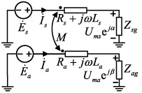
Equivalent circuit model of the grounding mode in Fig. 2.

Equivalent circuit model of the proposed novel grounding mode.
In Fig. 4, 𝛼1 and 𝛽1 are the phase angles of the A-phase terminal voltage with reference to
Since E
s
and E
a
are much larger than U
ms
and U
ma
, O1∕2∕3∕4 approaches zero. Therefore, the solutions of (4) can be obtained as: 𝛼1, 𝛽1 = −π∕3 or 2π∕3 and 𝛼2, 𝛽2 = π∕3 or −2π∕3. For submarine cables in general, (𝛼1, 𝛼2, 𝛽1, 𝛽2) = (−π∕3, π∕3, −π∕3, π∕3) is the optimal solution that minimizes the total loss P3, and the optimal grounding impedances are then calculated numerically:
For a general three-phase submarine cable system, the voltages of different components under three different grounding modes are illustrated in Fig. 5. The
From Fig. 5, it is observed that the total voltage magnitudes of the three-phase metal sheaths and armors under the proposed novel grounding mode is between that of the non-interlinked grounding mode and that of the two-ends grounding mode. According to (6), the total circulating current magnitudes of the novel grounding mode is between that of the other two grounding modes in general. Therefore, the theoretical analysis shows that the proposed novel grounding mode can reduce the circulating currents compared to the two-ends grounding mode, but is less effective than the non-interlinked version of the proposed mode in suppressing the circulating currents.
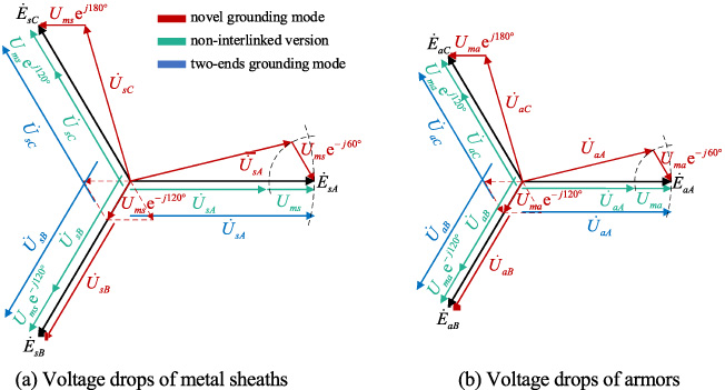
Comparison of voltage drops on cable lines under different grounding modes.
One considers a case that there is a ground fault on A-phase cable. Due to the distance between the adjacent submarine cables is usually 50–100 m, the core currents of B-phase cable and C-phase cable are considered unchanged. The core current of A-phase cable is assumed to be k times the original value (k is a real, k ≫ 1). To compare the magnitudes of voltages on the impedances Zsg1 and Zag1, one needs to decompose the unbalanced electromotive forces induced by core currents into anticlockwise (with subscript “1”), zero (with subscript “0”) and free (with subscript “f”) sequence components first, as shown in Fig. 6. The phase relationship of the sequence components is illustrated in Fig. 7, where
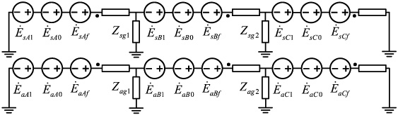
Schematic diagram of unbalanced electromotive forces decomposed into sequence components.
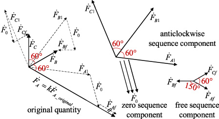
Phase relationships of sequence components.
One takes the phase angle of
Since the linear circuit satisfies the superposition principle, the voltages on the impedances Zsg1 and Zag1 can be regarded as the superposition of voltages generated by each set of sequence components. It is obvious that zero-sequence induced electromotive forces will not contribute to the terminal impedance voltages. The magnitude of free sequence components is smaller than that of other sequence components, therefore the contribution of free sequence components is neglected. From this point of view, the grounding impedance voltage under the ground fault approximates the voltage generated by anticlockwise sequence components, as formulated by
A 1600 mm2 220 kV submarine cable is taken as the case study for field-circuit coupling simulations. The total length of the submarine cable line is set to 30 km. The voltage limit of the metal sheaths is set to 1 kV, and that of the armors is set to 600 V. For the novel grounding mode and the non-interlinked version of it, the current rating depends on the grounding impedances of sheaths and armors, meanwhile the grounding impedances are decided by the current rating. However, the optimal terminal voltages are always the same for any current ratings. Consequently, one can substitute the grounding impedance with a voltage source of assigned magnitude and optimal phase, to numerically compute the current rating first. Then the circulating currents can be derived directly from the simulation, and the grounding impedances are obtained according to (3) and (5). For the single-phase ground fault simulation, the calculated grounding impedances are utilized to replace the voltage source, and the core current of A-phase cable is assumed 10 times the fault-free value. All the simulation results are listed in Table 1, from which one can observe that the current rating under the novel grounding mode is 2.69% higher than that under the two-ends grounding mode, but not as high as that under the non-interlinked version of the novel grounding mode. Meanwhile, the fault-phase terminal voltages under the novel grounding mode are reduced by about 500 V compared with the non-interlinked version. In summary, the numerical results validate the theoretical analyses above and the excellent comprehensive performance of the novel grounding mode.
Numerical results of field-circuit coupling simulations under three grounding modes
Numerical results of field-circuit coupling simulations under three grounding modes
Note: “loss ratio” means the sheath and armor loss as a percentage of the total loss.
The contribution proposes a novel grounding mode for submarine cables to enhance the permissible current rating within the voltage limits of metal sheaths and armors, and to reduce the inductive terminal voltage under the single-phase ground fault. The two-ends grounding mode and the non-interlinked version of the proposed mode are introduced to compare with the proposed novel grounding mode. For the best performance, the optimal grounding impedances are first investigated, and the computing method of the grounding impedances is given. Then through theoretical analyses and numerical calculation, it is validated that the proposed novel grounding mode can enhance the current rating compared to the two-ends grounding mode, meanwhile can reduce the terminal voltage of metal sheaths and armors of faulty cables compared to the non-interlinked version of the proposed mode. Moreover, the theoretical analyses show that the proposed novel grounding mode has comprehensive performances for general submarine cables.