
Abstract
This paper deals with the design and analysis of a surface-mounted outer rotor in-wheel motor (IWM) with the aim of reducing cogging torque and torque ripple for electric vehicles. The proposed IWM is equipped with axial sinusoidal surface-mounted permanent magnets (PMs), with the purpose of producing sinusoidal air gap flux density distribution, thus to realize sinusoidal back electromotive force (EMF) and smooth electromagnetic torque. To highlight the advantage of the proposed IWM, the conventional IWM with tile-shaped PMs and the IWM with stepwise-shaped PMs are also studied for comparison. The finite element method in the commercial software package is utilized to analyze the performance of the three motors, including the radial flux density of air gap, back EMF, cogging torque, and electromagnetic torque. Through the quantitative comparison, it is found that the proposed IWM greatly reduces the cogging torque, highly improves the sinusoidality of back EMF, and nearly eliminates the torque ripple.
Introduction
In recent years, the electric vehicles (EVs) have been greatly promoted and applied in both commercial and residential markets, due to their advantages of low noise, environmental friendliness, and non-usage of fuel. As one of the EVs key components, the high-performance motors are gaining popularity on account of the growing concerns about energy conservation and environmental protection. Particularly, the permanent magnet (PM) in-wheel motor (IWM) drive system has attracted much attention, the motor is placed near the wheel or directly in the wheel, with the merits of simple structure, reliable operation, high ruggedness, high efficiency, and high torque density [1–3].
The conventional surface-mounted outer rotor IWMs for EVs with tile-shaped PMs have many disadvantages in terms of high torque ripple and high cogging torque, thus bringing high vibration to the IWMs. The high vibration will produce damaging friction between components, and lead to unstable operation of the IWMs and the lower comfort of EVs [4]. To address this problem, the design methods are presented for reducing or eliminating torque ripple and cogging torque by way of modifications to the motor structure and PM shape. Eccentric PM shape widely applied in the industry can effectively reduce the harmonic components of the air gap flux density, which can lower the cogging torque and suppress torque ripple [5]. In [6], a PM combination of multiple PMs with the same material and different thickness and width is proposed, by which the harmonic content of the magnetomotive force can be reduced and the harmonic content in the air gap magnetic density can be weakened. A method is proposed to optimize the PM shape by adding the 3rd, 5th, 7th and 9th harmonics to the PMs until the harmonic content in the air gap flux density is minimized [7]. In [8], the savings of magnet cost and the suppression of torque ripple can be achieved by using multi-grade PMs. Apart from the above circumferential and radial optimization, the optimization of motor structure and PM shape in the axial direction has also attracted the attention. Skewing the stator or rotor PMs enables theoretical reduction of cogging torque to zero, whereas it is found that there was no improvement in torque ripple when the PM motor was run at rated current [9]. In [10] and [11], by composing near-sine stepwise-shaped PM of tile-shaped PMs with unequal pole arc coefficients in the axial direction, the proposed motor can effectively suppress the cogging torque and torque ripple. But due to the complex structure of stepwise-shaped PMs, the assembly of the proposed motor is complicated and requires high precision.
In this paper, an outer-rotor in-wheel motor (IWM) with axial sinusoidal surface-mounted PMs is proposed to suppress cogging torque and torque ripple. Firstly, the parameters and configuration of the proposed IWM, as well as the conventional IWM with tile-shaped PMs and the IWM with stepwise-shaped PMs, are introduced in detail. Secondly, the working principle of axial sinusoidal PMs is derived. Finally, the three-dimensional (3-D) finite element analysis (FEA) method is used to analyze the characteristics of the three models, and the FEA results are compared to evaluate the performance of the proposed IWM.
Topologies of the three models
To demonstrate the merits of axial sinusoidal PMs for the proposed IWM, two conventional models are studied for comparison. They are the conventional IWM model with tile-shaped PMs as model I, and the IWM model with stepwise-shaped PMs as model II, with the rotors shown in Fig. 1(a) and Fig. 1(b). The PMs of model II are designed as the whole blocks, but retain nearly sinusoidal stepwise shape. The proposed IWM model is nominated as model III, whose rotor is illustrated in Fig. 1(c). Both the axial sinusoidal PMs and the stepwise-shaped PMs can be processed by additive manufacturing technology [12]. The identical stator of the three models is displayed in Fig. 1(d). To obtain reasonable comparison results, the volume amounts of PMs are the same for all three models. In addition, the other parameters and configurations of the three models are also the same.
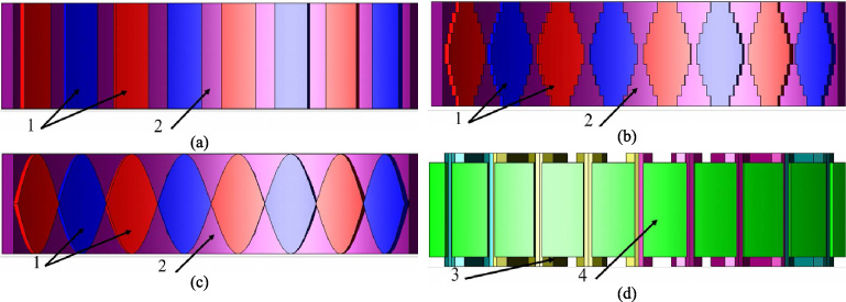
Topology of the three models. (a) The rotor of model I. (b) The rotor of model II. (c) The rotor of proposed model III. (d) Stator and windings. 1 – PMs. 2 – Rotor core. 3 – Windings. 4 – Stator core.
The investigated IWMs adopt the combination of 32 poles and 36 slots by considering the relationship between the electrical frequency and the inverter switching frequency. Then taking into account the space limitation, the fractional slot concentrated windings are used to shorten the winding end. The IWMs have the characteristics of low speed, high torque and direct drive, therefore, four parallel branches are adapted to meet the limitations of low voltage and high current. With such a winding arrangement, the IWM can be regarded as consisting of four 8-pole, 9-slot unit motors, while each unit motor has no cross-coupling of windings. The rotor is mounted with radially magnetized bonded NdFeB (Br = 0.703 T, 20 °C) to provide excitation. The silicon steel used in the stator core and rotor core is 35H440. The configuration of the quarter model of the proposed IWM is illustrated in Fig. 2, and the specifications for the three model are shown in Table 1.

Quarter model of the proposed IWM.
Specifications for the proposed IWM
As to the IWM using axial sinusoidal PMs, the flux linkage of each phase winding is equal to
From Lenz’s law, the no-load back EMF can be given by
Based on Eqs (2) and (3), it’s observed that the flux linkage of per phase winding follows a sinusoidal variation, and the back EMF also fluctuates in a sinusoidal variation owing to the axial sinusoidal PM. Without considering the effect of armature reaction, the under-load induced EMF e is equal to the no-load back EMF e
n
, which is given by
Analysis conditions
Although the 3-D FEA requires more time consumption, it is utilized by using a commercial software package here for more accuracy results, owing to the axial sinusoidal PM shape of the proposed IWM. The proposed model III, as well as the conventional model I and model II, has the same main dimensions, except for the PM shape, as shown in Table 1. The same PM volume is needed to achieve a reasonable comparative performance analysis. When the rotor is not moving and no excitation is applied, the radial flux density distribution of the air gap is obtained. According to the definition, there is no excitation source involved in the back EMF and cogging torque. Therefore, the back EMF, and the cogging torque is analyzed under no-load conditions. To determine the electromagnetic torque and loss of the three models, the three-phase balanced sinusoidal current excitation with the RMS value of 85.56 A is used.
Radial flux density of air gap
The radial flux density distribution of the air gap has a great influence on the electromagnetic performance of PM motors, in terms of back EMF, the cogging torque, the electromagnetic torque and loss. The distributions of three models along the axial and circumferential directions are illustrated in Fig. 3. There are two typical features that can be found in the radial flux density. The first is that the radial air gap flux densities of model II and model III show a sinusoidal distribution in the axial direction, and the second is that the leakage flux exists at the end of PM motors.

Distribution of the radial flux density of air gap. (a) Model I. (b) Model II. (c) Model III.
To improve the visualization of the 3-D radial air gap flux density distribution, the average value of the axial integration of the radial air gap flux density B
aa
, which can demonstrate the influence of axial sinusoidal PMs, is used as expressed by
The aforementioned radial air gap flux density B aa is shown in Fig. 4(a). It shows that there is a large distortion in the radial air gap flux density waveform at the slot position. To further evaluate the sinusoidal quality of the radial flux density, a fast fourier transform (FFT) is employed, as displayed in Fig. 4(b). The total harmonic distortions (THDs) of the radial flux density are 28.51%, 16.34%, and 15.26%, respectively. Due to the utilization of tile-shaped PMs, the radial air gap flux density waveform of model I shows a square wave shape and has the high harmonic contents. Although the teeth and slots have a significant bad effect on the air gap magnetic density of model III, it still demonstrates a better sinusoidal radial flux density than model I and model II, due to the adoption of the axial sinusoidal PMs.

The average value of the axial integration of the radial air gap flux density B aa . (a) B aa at different rotor positions. (b) Corresponding spectra.
The phase back EMF and the corresponding spectra of the three models are illustrated in Fig. 5. The third and fifth order components, dominating the back EMF harmonics, are enlarged. As shown in Fig. 5(a), model I has a highest peak to peak value of back EMF, because the end leakage has the least effect on it. Due to the larger effect of the end leakage, the fundamental component of model III is slightly smaller than those of model I and model II, as shown in Fig. 5(b). The THDs of the back EMFs of the three models are 2.57%, 1.00%, and 0.60%, respectively. Because of the short-chord winding, model I also exhibits a relatively good sinusoidal waveform, and its harmonic content is not too high. By comparing the FFT results, model III has the best sinusoidal back EMF. Its harmonic content is nearly absent, which verifies the correctness of the theoretical derivation of (3) and the advantages of the axial sinusoidal PMs.

The back EMF. (a) Back EMF. (b) Corresponding spectra.
The cogging torque comparison for the three models is shown in Fig. 6. Due to the relative motion of the slot opening and the PMs, the increase or decrease of co-energy contributes to the generation of the cogging torque. Consequently, cogging torque can be minimized by smoothing out the fluctuation of co-energy. Model III exhibits a peak-to-peak value of cogging torque as 0.327 Nm, which is 70.73% and 40.22% less than those of model I and model II, respectively. This is mainly because the co-energy in air-gap changes more smoothly. The corresponding spectra of the cogging torque is shown in Fig. 6(b). It can be observed that 1st, 2nd, 3rd, 4th, and other order key components of model III are almost eliminated, which uses the dominant harmonic of model I as the 1st order component. This shows that the axial sinusoidal PMs can effectively reduce the low-order harmonic component of the cogging torque.
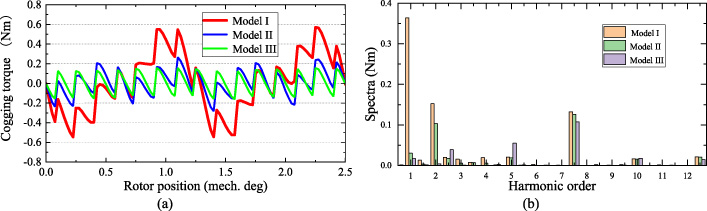
Cogging torque. (a) Cogging torque. (b) Corresponding spectra.
The comparison of electromagnetic torques and corresponding torque harmonic spectra is shown in Fig. 7. The model I has the maximum average torque, yet it also shows the highest torque ripple, which is given by

Electromagnetic torque. (a) Electromagnetic torque. (b) Corresponding torque harmonic spectra.
It is known that the harmonic components of back EMF results in the generation of iron loss. The 3-D FEA is also utilized to calculate the iron losses for better accurate results, while analyzing the electromagnetic torque. The results are shown in Table 2. The iron loss of model III is smaller than those of model I and model II, because of its minimal THD of back EMF. Since the winding size and number of turns are the same, the copper losses of all three models are also the same. Though the output power of model III is the lowest, it still retains a similar efficiency compared to the other two models, wherein the efficiency shown is calculated by
The overall performance of the three models is summarized in Table 2.
Performance of the three models
This paper has proposed an outer-rotor IWM with axial sinusoidal surface-mounted PMs, to achieve sinusoidal back EMF and low torque ripple. To highlight the advantage of the proposed IWM, the conventional IWM with tile-shaped PMs, and the IWM with stepwise-shaped PMs were also studied for comparison. And the working principle of axial sinusoidal PMs was derived. Based on the 3-D FEA results of the three models, it could be seen that the proposed model had a better sinusoidal flux density distribution of air gap, and exhibited a sinusoidal back EMF with fewer harmonic components. Furthermore, the proposed IWM greatly reduced the cogging torque by 70.73% and 40.22%, and decreased the torque ripple by 4.4% and 0.85%, respectively, when compared to the two conventional models.
Footnotes
Acknowledgements
This work was supported in part by the Natural Science Foundation of Shandong Province of China for Outstanding Young Scholars under Grant ZR2021YQ35, in part by the National Natural Science Foundation of China under Grant 52077123 and 51737008, and in part by Open Research Fund of State Key Laboratory of Large Electric Drive System and Equipment Technology in China under Grant SKLLDJ032020005.