
Abstract
To increase the output displacement of the linear piezoelectric actuator, a linear piezoelectric actuator with large displacement and three operation modes is proposed. The operating principle of the piezoelectric actuator is presented. The magnification factor of the displacement amplification mechanism is deduced and verified by finite element analysis. To improve the output precision of the actuator, a feedforward PID control model is established. Based on the experimental test platform, the output characteristics of the piezoelectric actuator are tested. Results show the maximum output displacement of the piezoelectric actuator is 558.3 μm under a driving voltage of 150 V with two piezoelectric stacks. When the driving frequencies are less than 3 Hz, the control accuracy of feedforward PID is higher than that of PID, and the error between the measured displacement and the ideal value is less than 10% after applying the control to the piezoelectric actuator.
Introduction
In recent years, with the development of science and technology, precision drive and transmission technology have gained vigorous development, and various types of driving mechanisms emerge endlessly [1–4]. Miniaturization and integration of precision drive mechanisms have become the development trend. Therefore, as the core component of micro-machinery, the micro actuator has been the focus of research. With the advantages of small volume, high precision and fast response, piezoelectric actuators have been applied in precision positioning, micro-robot, biomedical engineering, and other modern micro precision engineering [5–8].
As an important application in the field of precision positioning, the linear piezoelectric actuator has attracted the attention of many researchers. And various linear piezoelectric actuators have been developed. According to the excitation mode of the piezoelectric actuators, it can be divided into resonant and non-resonant piezoelectric actuators. The resonant piezoelectric actuator [9,10] is driven by the resonance of the piezoelectric vibrator, while the non-resonant actuator [11,12] is actuated by the non-resonant frequency excitation signal.
The resonant piezoelectric actuator is one of the most widely studied piezoelectric actuators. It is widely used in precision positioning, micro-robot, and other fields. Liu et al. [13] proposed a new type of longitudinal and bending coupled standing wave piezoelectric actuator with a maximum speed and thrust of 891.3 mm/s and 39.2 N at a voltage of 29.4 kHz and 400 V. Because of the use of ultrasonic vibration, it has the characteristics of high speed, and large load capacity. Based on the longitudinal-bending coupling mode, a novel standing wave linear ultrasonic motor with double driving feet is designed [14]. The motor consists of four pieces of piezoelectric ceramics on a metal beam. Under a voltage of 200 V and a preload of 3 N, the maximal no-load velocity of the motor is 147.78 mm/s, while the maximum thrust force is 1.1 N when the voltage and preload are 200 V and 6 N, respectively. What’s more, Smithmaitrie et al. [15] developed an ultrasonic linear piezoelectric motor with dual piezoelectric actuator patches. The motor consists of a linear stator, a pre-load weight, and two piezoelectric actuator patches. And the stator generates propagating waves when the piezoelectric actuators are subjected to harmonic excitations. Compared with the traditional piezoelectric motor, the proposed motor has a simpler structure with a smaller number of actuators and lower stator stiffness.
The non-resonant piezoelectric driving mechanism usually uses a piezoelectric stack as the driving source. Its characteristic is the output force of the piezoelectric actuator is large, and it can achieve low-speed movement. To reduce the number of driving signals, a piezoelectric inchworm actuator with a single DC excitation signal is proposed [16]. Under the driving frequency of 3.2 Hz and driving voltage of 75 V, the output gait displacement of the actuator is 0.241 μm. Modulated by the electromagnetic field, a novel type of noncontact linear piezoelectric actuator is developed [17]. The proposed actuator utilizes electromagnetic force to transfer the motion between the stator and the runner. Under the driving frequency of 1 Hz and driving voltage of 100 V, the actuator can output a thrust of 0.15 N and a speed of 0.33 mm/s. To realize the motor with high precision, large stroke, and strong thrust, a non-resonant piezoelectric linear motor with alternating normal contact force is designed [18]. The motor uses four piezoelectric stacks to excite the two driving feet, which alternately push the mover to generate unidirectional motion. What’s more, Liu Y.X.’s research team [19–21] has conducted a series of research on piezoelectric linear actuators in recent years. An inchworm rotary piezoelectric actuator inspired by finger twist is designed, which can achieve a maximum rotation speed of 0.16 rad/s, a carrying load of 0.5 kg, and an output torque of 0.05 N ⋅ m under a voltage of 150 V and a frequency of 20 Hz. And another compact inchworm piezoelectric actuator with two multi-function driving feet is developed to output large force and achieve high output speed without backward motion. Besides, Based on the working principle of the three-petal mouth of a rabbit, a ring-shaped linear piezoelectric actuator is manufactured and tested. The actuator has a wide range of speed adjustments and can be used to drive a hollow cylinder mover along different slopes without other auxiliary structures.
Through the above analysis, a variety of linear piezoelectric actuators have been designed and manufactured. However, the current linear piezoelectric actuators still have the disadvantage of small output displacement. Therefore, a linear piezoelectric actuator with large displacement and multi-range is designed in this paper. Compared with other linear piezoelectric actuators, the piezoelectric actuator proposed in this paper can realize three operating modes, and has a large displacement and can cope with different working conditions. For the piezoelectric actuator, operating mode one is suitable for the working condition with large displacement demand and small load. Operating mode two is suitable for small displacement demand, and small load conditions. However, operating mode three is suitable for large displacement demand, and large load conditions.
In this paper, the operating principle of the piezoelectric actuator is presented. The control method of the piezoelectric is analyzed. Based on the experimental test platform, the output characteristics of the piezoelectric actuator are tested. The results lay a theoretical foundation for improving the performance of the piezoelectric actuator.
Operating principle of the piezoelectric actuator
Figure 1 shows the structure of the large displacement multi-range linear piezoelectric actuator. It is mainly composed of the displacement amplification mechanism, displacement output mechanism, and auxiliary assembly mechanism. The displacement amplification mechanism includes two piezoelectric stacks and a flexure hinge amplifying mechanism, the displacement output mechanism includes a guide rail and an output moving platform, and the auxiliary assembly mechanism includes a base, a shell, an end cover, and two pre-tightening screws.
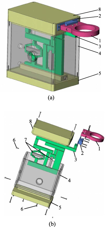
Structure of the large displacement multi-range linear piezoelectric actuator. (a) The assembly drawing. (b) The exploded drawing. (1) Output moving platform. (2) Guide rail. (3) Flexure hinge amplifying mechanism. (4) Shell. (5) Base. (6) Pre-tightening screws. (7) Piezoelectric stacks. (8) End cover.
The displacement amplification principle of the piezoelectric driver is shown in Fig. 2, it constitutes three operating ranges according to the driving voltage applied to the piezoelectric stacks. When the voltage is applied to the right piezoelectric stack alone (operating mode one), the piezoelectric stack produces elongation deformation, the amplification displacement of the lever on the right Δd a and the amplification displacement of the lever on the right Δh a are coupled by lever mechanism at the top to output the amplification displacement (see Fig. 2(a)). When the voltage is applied to the left piezoelectric stack alone (operating mode two), the piezoelectric stack produces elongation deformation, the displacement which is amplified by the bridge mechanism and the lever mechanism on the left side Δd b is amplified by the upper lever mechanism to output the amplified displacement (see Fig. 2(b)). When the voltage is applied to the two piezoelectric stacks (operating mode three), the piezoelectric stacks produce elongation deformation, the displacement which is amplified by the bridge mechanism and the lever mechanism on the left side Δd b and the amplification displacement of the lever on the right Δh a are coupled by lever mechanism at the top to output the amplification displacement.
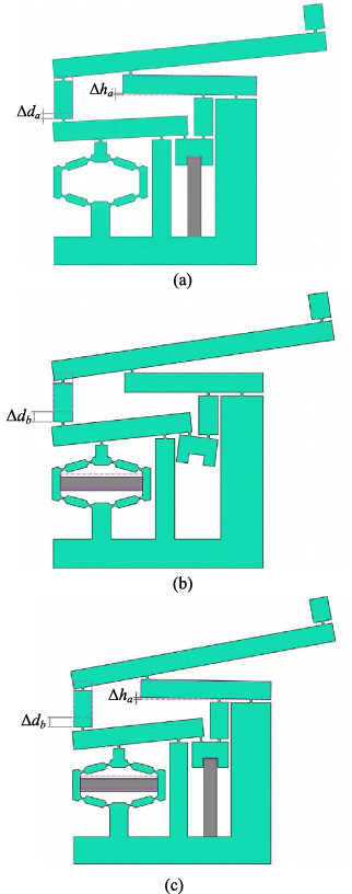
Schematic of displacement amplification of the piezoelectric actuator. (a) Operating mode one. (b) Operating mode two. (c) Operating mode three.
Therefore, according to different needs, the different ranges of the piezoelectric actuator can be selected to achieve the purpose of multi-purpose.
In the displacement amplification mechanism, the bridge amplification mechanism adopts a bow flexible hinge, and its geometric parameters are shown in Fig. 3. Where t is the minimum thickness at the cut of the flexure hinge, θ m is the central angle corresponding to the bow, r is the radius of the circle corresponding to the bow, and w is the overall thickness.

Structure parameters of bow flexure hinge.
The bending stiffness k
𝛼 and tensile stiffness k
l
of the bow flexure hinge are:
The principle diagram of the bridge amplification mechanism is shown in Fig. 4. By applying force F to both ends of the piezoelectric stack, deformation Δx is generated horizontally. Through elastic deformation, the amplified output displacement Δy is obtained in the radial direction.
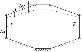
Schematic diagram of the bridge amplification mechanism.
The bridge amplification mechanism has a symmetric structure, and one of the bridge arms is taken for analysis. The force model is shown in Fig. 5. The two sides of the bridge arm of the flexible mechanism are affected by the horizontal force F A and F B , and the torque M a and M b are generated at the hinge A and B respectively.

Force model of bridge arm.
According to the principle of force balance, the torque on the AB bridge arm is:
Apply horizontal tension F to point A of bridge arm AB, and the displacement at point A in the horizontal direction is Δx. The equilibrium equation can be established as follows:
Substituting Eqs (3) and (4) into Eq. (5), it can be obtained:
Combining Eqs (6) and (7), it can be written as:
Substituting Eq. (1) into Eq. (8), it can be obtained:
With the decrease of the angle of the hypotenuse, the magnification ratio can be increased to infinity. However, due to the deformation of the flexure hinge itself and the fact that the element is not an absolutely rigid body, the magnification ratio of the bridge magnifying mechanism will have a limited value. To make the size as small as possible and improve the magnification as much as possible, the bridge magnifying mechanism meets the bar requirement of a certain strength. At the same time, considering the difficulty of processing, the basic dimension parameters of the bridge magnifying mechanism are determined as shown in Table 1.
The lever amplification structure of this structure can be simplified as shown in Fig. 6. Among them, flexion hinge B is the input end of piezoelectric ceramics passing through the bridge amplification mechanism, flexion hinges D and F are the direct input end of piezoelectric ceramics, flexion hinge K is the total output end of this structure, and the point I is the fulcrum of moving lever.

Simplified diagram of the lever amplification mechanism.
Parameters of the bridge amplification mechanism
When the piezoelectric actuator is in operating mode one (Fig. 2(a)), the piezoelectric stack directly generates deformation Δx a to the flexural hinge D and F, the amplification result of this structure is shown in Fig. 7.
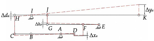
Operating mode one of the lever amplification mechanism.
In Fig. 7, the displacement Δd
a
at flex hinge H is amplified by lever DAC, and Δh
a
at flex hinge J is amplified by lever EFG
For lever HJK, flexible hinges H and J are both input ends. Since the input displacement direction is opposite, the rotation origin of lever is in the middle of flexible hinge H and J. The distance between H and I, and the distance between I and J can be written as:
Therefore, the displacement Δy
a
of the total output end K is:
Substituting Eq. (11) into Eq. (12), it can be gained:
Substituting Eq. (10) into Eq. (13), it yields:
When the piezoelectric actuator is in operating mode two (Fig. 2(b)), only the piezoelectric stack generates deformation Δx b = 𝜆Δx a to the flexible hinge B through the bridge amplification mechanism. The amplification result of this structure is shown in Fig. 8.

Operating mode two of the lever amplification mechanism.
According to the lever amplification principle and similar triangle theory, the displacement Δd
b
generated by lever BAC amplification at flexure hinge H is:
Among them, flexible hinge J has no displacement, so as the lever rotates the point I, the displacement Δy
b
of the total output end K can be obtained:
Substituting Eq. (15) into Eq. (16), it can be obtained:
When the piezoelectric actuator is in operating mode three (Fig. 2(c)), the piezoelectric stack directly inputs the displacement Δx a to the flexural hinge F, and another piezoelectric stack inputs the displacement Δx b to the flexural hinge B through the bridge amplification mechanism. The amplification result of this structure is shown in Fig. 9.

Operating mode three of the lever amplification mechanism.
Substituting Eqs. (10) and (15) into Eq. (13), the displacement Δy
ab
of the total output end K can be obtained:
Theoretically speaking, the amplification ratio of the lever amplification mechanism is infinite. However, since the beam of the lever amplification mechanism is not an absolutely rigid body in theory, the load imposed on the end of the beam will increase with growth of the amplification ratio. This causes the deformation of the lever and affects the amplification ratio of the lever mechanism. At the same time, with the increase of amplification ratio, the arm length of the lever amplification mechanism will increase, which makes the mechanism occupy too much space and affects the compactness of the mechanism. To make the size as small as possible and the magnification as large as possible, the basic size parameters of the lever magnifying mechanism are determined through design and calculation, as shown in Table 2.
Parameters of the bridge amplification mechanism
According to Eqs ((14)), ((17)) and ((18)), the overall amplification factor of the displacement amplification mechanism is 22.263, 10.881 and 23.274, respectively.
In this paper, two piezoelectric stacks are used to increase the output displacement and output force of the piezoelectric actuator. Although a large output displacement can be achieved by a single large displacement piezoelectric stack, the large displacement piezoelectric stack usually has a larger length, which is not conducive to the miniaturization of the piezoelectric actuator. In addition, three operating modes can be realized here through two piezoelectric stacks, and different driving modes can be selected according to different working requirements.
For operating mode one and operating mode three, the Δx a on the right side is the same, while the Δd a and Δd b on the left side have little difference, so there is little difference in the magnifiers under no-load condition. However, under load condition, because operation mode 3 has two piezoelectric reactors working, respectively providing Δx a and Δd b , it can provide greater output force and stronger load resistance. For operating mode two, a smaller range has a higher resolution. To sum up, operating mode one is suitable for the working condition with large displacement demand and small load. Operating mode two is suitable for small displacement demand, and small load conditions. However, operating mode three is suitable for large displacement demand, and large load conditions.
To verify the accuracy of the calculation results, a finite element analysis is carried out on the piezoelectric actuator. A displacement of 0.03 mm is applied to the position of the piezoelectric stack, and the finite element results are shown in Fig. 10. Meanwhile, the theoretical calculation value of the displacement magnification factor is compared with the simulation result, as shown in Table 3. Results show:
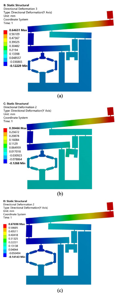
Simulation results of the piezoelectric actuator. (a) Operating mode one. (b) Operating mode two. (c) Operating mode three.
Comparison of displacement magnification factor
Under different operating modes, the calculated value of the magnification is close to the simulated value. And the maximum error is 6.7%. Furthermore, the correctness of the theoretical model is verified.
To eliminate the influence of hysteresis nonlinearity caused by the physical characteristics of piezoelectric material, an effective control algorithm should be adopted to control the piezoelectric actuator. PI hysteresis nonlinear model is a classical piezoelectric model. The PI model of the described object can be constructed by adding multiple hysteresis operators with different thresholds and weights, and its expression is as follows:
On this basis, the inverse of PI hysteresis model is calculated to compensate, and the mathematical expression of the inverse model is as follows:
In this paper, feedforward PID compound control is constructed based on the combination of PI hysteresis inverse model and PID control. The system block diagram is shown in Fig. 11.
In Fig. 11, r (t) is the expected input of the system, e (t) is the error between the expected input and the actual output of the system, u (t) is the actual input of the system, and y (t) is the actual output of the system. In the feedforward channel, the hysteresis inverse model is first used to compensate the hysteresis characteristics of the piezoelectric stack itself. Then the remaining small error is transferred to PID control through the feedback path to continue to control the piezoelectric stack. Therefore, the control task undertaken by the PID controller in the feedforward PID compound control is smaller than that undertaken by the feedback control, so the rapidity of the feedforward PID compound control is better than that of the simple PID control under the same task index.
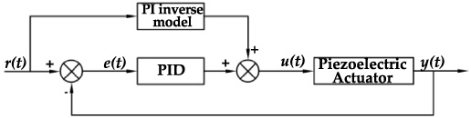
Feedforward PID compound control system.
In practical applications, in order to adapt to computer control, discrete PID is usually used, and the expression is as follows:
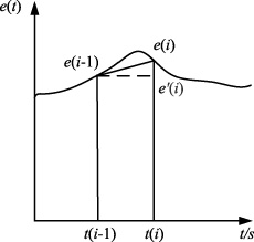
The conventional integral element is a rectangle composed of e (i − 1), e ′ (i), t (i − 1) and t (i), whose height is e (i − 1) and width is T. When using this integral element, if the deviation value e (t) changes too much, the rectangular integral will produce a large error. The integral element is improved to a trapezoidal integral element consisting of e (i − 1), e (i), T (i − 1), and t (i), which is selected as the deviation values of two adjacent sampling moments, e (i − 1) and e (i), respectively, and the height is T, as shown in Fig. 12.
Conventional integrators and their improvement.
This improvement can reduce the error of the integration link and integrate the deviation more accurately. The expression of the integration link is:
Differential link is very sensitive to interference, too large interference will cause the control quantity change amplitude to be too large and too fast, resulting in the control precision of the whole system being reduced. The separation method is used to improve the differential link: when the controlled object is affected by interference and produces a large deviation, the differential link is removed, to avoid the instability of the system; when the error of the controlled object is small, the deviation is normally differentiated, and the differential link is preserved to speed up the transient response of the system. After improvement, the expression of the differential link is:
Therefore, the PID discretization expression obtained by improving the integral and differential links is as follows:
According to Eq. (26), it can be seen that the output control voltage at a certain moment needs to be superimposed on the deviation between the current moment and the previous moment. This method not only consumes a large amount of computer memory, but also takes a long time between calculations, making it difficult to achieve fast control. Therefore, it is improved recursively. The expression of output control voltage at k − 1 is:
By subtracting Eq. (26) from Eq. (27), we get:
After simplification, the coefficients are as follows:
To sum up, the output control voltage u (k) of the PID controller with recursion relationship at the current moment is only related to the deviation e (k) at the current moment and the deviation e (k − 1) and e (k − 2) at the first two sampling moments. Therefore, the improved scheme can reduce computing time and memory consumption, and it is easy to realize fast control.
In the feedforward channel, the hysteresis inverse model is first used to compensate the hysteresis characteristics of the piezoelectric stack itself. Then the remaining small error is transferred to PID control through the feedback path to continue to control the piezoelectric stack. Therefore, the control task undertaken by the PID controller in the feedforward PID compound control is smaller than that of the feedback control, so the rapidity of the feedforward PID compound control is better than that of the simple PID control under the same task index.
Experiments were carried out on the proposed piezoelectric actuator to further verify the advantages of feedforward PID control. Figure 13 shows the experimental test system of the piezoelectric actuator. The output displacement is tested by LVDT inductive micro-displacement measuring instrument. The signal is sent out and the displacement is collected by NI multi-function data acquisition card. The control scheme is completed by the LabVIEW program on the upper computer.
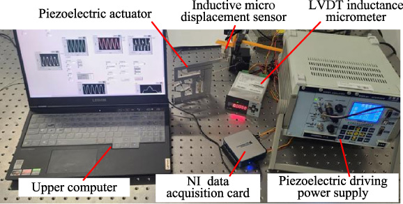
Experimental test system of the piezoelectric actuator.
In this paper, the sinusoidal signal with a maximum driving voltage of 150 V is applied to the piezoelectric actuator, and the hysteresis loop (voltage–displacement curve) of the actuator is obtained by collecting its actual output displacement. At the same time, the total number of operator n is 15, and the least square method is used to identify the parameters of the PI hysteresis model. The results are shown in Table 4.
PI hysteresis model parameters
In order to verify the validity of the hysteresis model established in this paper, the same input model as the actual system is applied to the model, and the obtained model curve is compared with the measured curve. Among them, due to the use of a contact sensor in this paper, the measured displacement curve will fluctuate due to the influence of inertia, damping, and other external interference. In order to reduce fluctuation, the db4 wavelet was used to decompose the signal with a scale of 7. The high-frequency coefficients of layers 1–5 were directly set to 0 by using the hard threshold method, and the coefficients of the other layers remained unchanged. The fitting results after reconstruction by inverse wavelet transform were shown in Fig. 14.
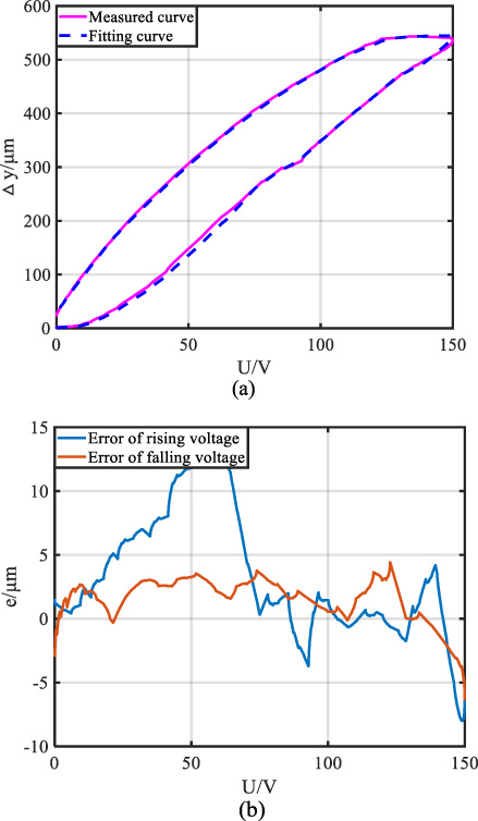
Output displacement curve of the piezoelectric actuator. (a) Displacement varies with time. (b) Error curves.
As can be seen from Fig. 14, in the range of the maximum displacement value of the piezoelectric actuator of 544.6 μm, the maximum absolute fitting error of the measured curve and the model curve is 15.0153 μm. The average absolute fitting error is 3.0494 μm. This shows that the PI hysteresis model established in this paper can better characterize the hysteresis phenomenon of the piezoelectric actuator.
Based on the above analysis, the inversion of the PI hysteresis model is calculated to compensate for the nonlinear of the system. Substituting the parameters in Table 4 into the inversion model and the parameters are shown in Table 5.
PI hysteresis inverse model parameters
When the piezoelectric actuator operates in mode one, the comparison of PID control, feedforward PID control, uncontrolled and ideal displacement is shown in Fig. 15. Since the piezoelectric actuator operates at low frequencies, only driving frequencies of 1 Hz and 2 Hz is presented in Fig. 14.
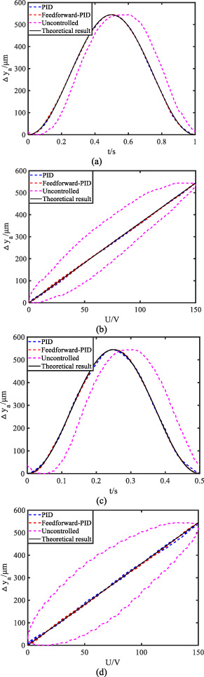
Output characteristics of the piezoelectric actuator operated in mode one. (a) Displacement varies with time at 1 Hz. (b) Displacement varies with voltage at 1 Hz. (c) Displacement varies with time at 2 Hz. (d) Displacement varies with voltage at 2 Hz.
Figure 15(a) and (c) show the output displacement of the piezoelectric actuator with time under sinusoidal voltage. The output lag of the piezoelectric actuator can be seen by comparing the fitting degree of curves under various controls with the ideal curve. By comparing the time-displacement curves of each frequency, it can be seen that the maximum output displacement is 544.6 μm when the actuator works in mode one. Meanwhile, it can be seen that with the increase in the driving frequency, the output lag of the piezoelectric actuator gradually increases. At the same time, it can be seen that when the error increases, the lag compensation result is relatively ideal because the feedforward PID control adds a feedforward module to reduce the error.
The curve in Fig. 15(a) and (c) can only reflect the hysteresis characteristics of the piezoelectric actuator. In order to compare the nonlinearity under different control schemes, Fig. 15(b) and (d) are introduced. The curves in Fig. 15(b) and (d) show the variation of the output displacement of the piezoelectric actuator with the voltage under sinusoidal voltage. The degree of nonlinearity of the piezoelectric actuator can be seen by comparing the fitting degree of the curve under each control with the ideal result curve. Under lowfrequency driving, the output of the piezoelectric actuator is linear with PID and feedforward PID control.
In order to obtain the compensation effect of piezoelectric actuator output displacement under different control schemes, the average absolute errors of the PID control and feedforward PID control at different frequencies are investigated, as shown in Table 6.
The average absolute error of each control scheme for operating mode one
According to Table 6, the average absolute error of feed-forward PID control is less than that of PID control. What’s more, as the driving frequency of the piezoelectric actuator increases, the average absolute error increases in each control system.
When the piezoelectric actuator operates in modes two and three, the comparison of PID control, feedforward PID control, uncontrolled and ideal displacement output is shown in Figs. 16 and 17. Results show: The maximum output displacements of the piezoelectric actuator in modes two and three are 263.4 μm and 558.3 μm, respectively. Same as when the piezoelectric actuator operates in mode one, the output lag of the piezoelectric actuator increases as the driving frequency increases. When the piezoelectric actuator is operating in mode two, the compensation effect of displacement lag is better under the PID control and feed-forward PID control. However, when the piezoelectric actuator is operating in mode three, the control effect of feedforward PID control is better than that of PID control.
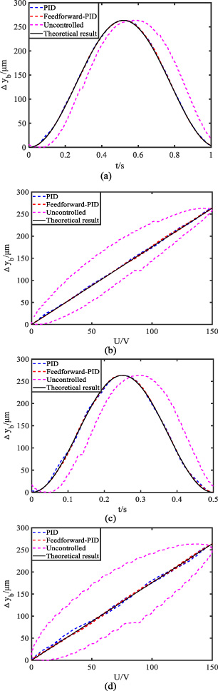
Output characteristics of the piezoelectric actuator operated in mode two. (a) Displacement varies with time at 1 Hz. (b) Displacement varies with voltage at 1 Hz. (c) Displacement varies with time at 2 Hz. (d) Displacement varies with voltage at 2 Hz.
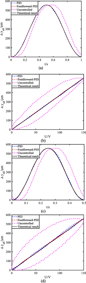
Output characteristics of the piezoelectric actuator operated in mode three. (a) Displacement varies with time at 1 Hz. (b) Displacement varies with voltage at 1 Hz. (c) Displacement varies with time at 2 Hz. (d) Displacement varies with voltage at 2 Hz.
In order to test the control effect under different control methods, the average absolute error is solved, as shown in Table 7. Meanwhile, the coincidence degree between the test displacement and theoretical value under different control methods is also investigated, as shown in Table 8. Since the piezoelectric actuator designed in this paper works in the low-frequency stage, only the control effect of 1–3 Hz is presented here.
The average absolute error of each control scheme for operating modes two and three
Coincidence degree between the test displacement and theoretical value under different control methods
The results show that the lower the driving frequency, the higher the control accuracy of the piezoelectric actuator. Meanwhile, the control accuracy of feedforward PID is higher than that of PID. When the driving frequency is less than 3 Hz, the coincidence of the test displacement and the theoretical value is over 90% under both PID and feedforward PID control.
A linear piezoelectric actuator with large displacement and multi-range is proposed. The operating principle of the piezoelectric actuator is presented. The magnification factor of the displacement amplification mechanism is deduced and a feedforward PID control model is established. Based on the experimental test platform, the output characteristics of the piezoelectric actuator are tested. Results show: The driver designed in this paper has a large output displacement. The maximum output displacement of the piezoelectric actuator is 558.3 μm under a driving voltage of 150 V with two piezoelectric stacks. For the magnification, the error of theoretical calculation and simulation results is within 7%. The control accuracy of feedforward PID is higher than that of PID. When the driving frequencies are less than 3 Hz, the error between test displacement and ideal value is within 10%.
Footnotes
Acknowledgements
This work is supported by the National Natural Science Foundation of China (51905228), the Qing Lan Project of Jiangsu Province (1024902201), and Postgraduate Research & Practice Innovation Program of Jiangsu Province (SJCX21_1752).
Conflicts of interest
The authors declare no conflict of interest.