
Abstract
By designing stator teeth using grain-oriented sheets (GO) and other parts still with non-grain-oriented sheets (NGO), the electromagnetic performance of the interior permanent magnet synchronous machine (GO-IPMSM) can be improved greatly. As the stator core of the designed GO-IPMSM is a hybrid core that is composed of two different silicon sheets, both the electromagnetic and mechanical performances are affected by the stator joint shape between GO and NGO sheets. Meanwhile, with the adoption of GO, the torque ripple of GO-IPMSM is increased though the average torque is increased as well. For reducing the torque ripple, optimizing the rotor barrier shape is an effective way. In this paper, the piecewise linear interpolation method is employed for establishing the stator joint shape between GO and NGO sheets, and the polynomial method is proposed to establish the rotor barrier shape. Through the analysis, it can be seen that the stator joint shape plays a strong role in affecting the mechanical performance of the GO-IPMSM, while the effect on the electromagnetic performance is weak. The genetic algorithm is used to optimize the rotor barrier shape for achieving high average torque and low torque ripple. Lastly, a quick and accurate efficiency map calculation method based on the Kriging model is proposed for GO-IPMSM with less finite element method (FEM) samples are required.
Keywords
Introduction
In recent years, with the development of permanent magnet (PM) materials, computer aid design methods, and control methods, the performance of permanent magnet synchronous machines (PMSM) has been improved greatly. Compared with other electrical machines, the PMSM has the merits of high torque ability and high efficiency. Therefore, it is a good candidate for electric vehicle drive applications [1].
Normally the non-grain-oriented sheet (NGO) is used for developing electrical machines, as the main magnetic fluxes operate in the 2D plane. Compared with NGO, the electromagnetic characteristic of grain-oriented silicon sheet (GO) is much better along its rolling direction, while that along the transverse direction is worse. In the past years, GO has been mainly employed for fabricating the transformer core. However, by analyzing the magnetic field of the electrical machine, it can be found that the magnetic flux on its stator teeth is nearly alternating. Taking advantage of the high permeability of GO along its rolling direction, it was employed for filling part of the magnetic barrier of a synchronous reluctance machine (SynRM). It showed that the torque ability of this machine has been improved greatly, especially when the applied current density is high as its d-axis magnetizing ability has been enhanced [2]. By using GO for fabricating stator teeth while stator yokes are still made by using NGO, the performance of axial-flux switched reluctance machine and PMSM for automotive applications has been improved [3,4].
By installing PM in different rotor positions, the PMSM includes the surface-mounted PMSM and interior PMSM (IPMSM). According to the difference in winding structure, the PMSM includes the fractional slot concentrated winding PMSM (FSCW), and integrated slot distributed winding PMSM (ISDW). Currently, the IPMSM has shown its higher torque ability than the surface-mounted PMSM as the reluctance torque existed [5]. The reluctance torque is produced by the difference of d-axis and q-axis inductance and is further determined by the rotor structure. However, the rotor structure of IPMSM is very complex, and it can be designed with various shapes to achieve good electromagnetic performance. Meanwhile, with the existence of cogging torque, the torque ripple of IPMSM is high as well. Both improving the machine structure and control algorithm can reduce the torque ripple. On the other hand, the average torque of the machine is decreased with the torque ripple is reduced. In [6], the relationship between the magnetic barrier shape and torque ripple of a multi-layer IPMSM is analyzed, and it can be seen that optimizing the magnetic barrier angle is an effective way to reduce the torque ripple. In [7], the torque ripple of an IPMSM is reduced by notching the rotor bridge with different shapes, while the average torque does not decrease. For achieving the best rotor barrier shape, a moving asymptotes-based topology optimization method (MMA) is proposed for a SynRM [8].
In this paper, an IPMSM with hybrid GO-NGO cores (for simplicity it is named GO-IPMSM) is designed, where GO is used for fabricating the stator teeth and the other stator part is still made by using NGO. In traditional design optimization, normally the main dimensions of the electrical machine are optimized and the effect of the rotor shape or the stator joint shape between the GO and NGO are ignored. In this paper, the shape optimization method is proposed to optimize the above shapes. For benchmark comparison, an IPMSM made all by NGO with 8 poles and 12 stator slots named NGO-IPMSM, and an IPMSM made all by NGO with 8 poles and 48 stator slots named NGO-IPMSM(48) are employed. Besides considering a great number of finite element method (FEM) samples are required for obtaining the efficiency map consumes much time, a quick efficiency map prediction based on the Kriging approximation model is proposed for calculating the efficiency map of the above machines.
In summary, the structure of the rest of the paper is as follows. Firstly, the effect of the stator junction shape of hybrid GO-NGO cores on the performance of the machine is explored in Section 2. Section 3 presents the modeling methodology of the rotor flux barrier and the shape optimization process to reduce the torque ripple of the machine. The results of the study are discussed and analyzed in Section 4. Section 5 presents a fast efficiency map prediction method based on the Kriging approximation model. Finally, the conclusions of the research results are summarized in Section 6.
Design of GO-IPMSM
With the adoption of GO replacing NGO on the stator teeth of electrical machines, the flux density on stator teeth can be increased and thus the electromagnetic performance can be improved. Considering the electromagnetic characteristic of GO and the manufacturing process, the GO sheets are stacked along the axial direction.
Pole and slot number selection
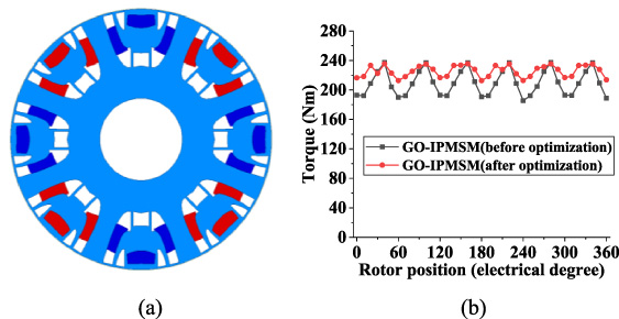
For the IPMSM with ISDW, adopting GO on the stator teeth is a challenge because the stator width is relatively narrow. Figure 1 shows a case study of GO IPMSM with 8 poles and 48 slots. After optimizing the electromagnetic performance, the stator teeth width, average torque, and torque ripple are 7 mm, 167 Nm, and 2%, respectively. With the adoption of GO, the average torque and torque ripple are increased to 172 Nm and 3%, respectively. For achieving the same average torque of 172 Nm, the core loss is reduced from 207 W to 205 W.
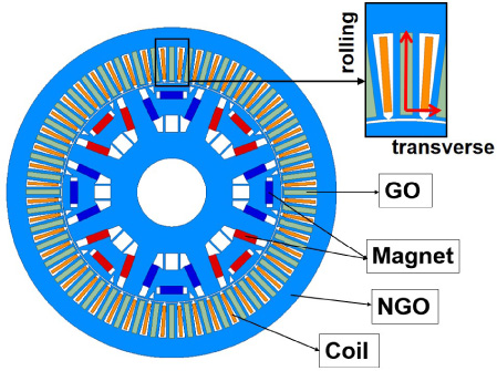
Main structure of GO-IPMSM with 8 pole 48 slots.
Compared to the PMSM of ISDW, the PMSM of FSCW has a much shorter winding end length. Therefore, the copper loss and weight can be decreased, and the efficiency and power density can be improved. While the PMSM with FSCW has the disadvantages of high PM eddy current loss and torque ripple. For achieving good output performance, PMSM with FSCW is normally designed with 8 poles and 12 stator slots [9,10]. Figure 2(a) shows the main magnetic structure of the IPMSM with FSCW analyzed in this paper, and the main dimensions and parameters are tabulated in Table 1.
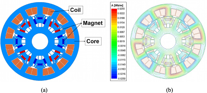
(a) Main structure of IPMSM with FSCW. (b) No load flux line distribution.
Main parameters of IPMSM
For establishing the stator joint shape between GO and NGO sheets, the piecewise linear interpolation method is employed as shown in Fig. 3. For simplification, the irregular GO shape is determined symmetrical to the stator tooth central line. Taking the right side as an example, there is an arc close to the stator’s outer side with one endpoint located on the central line, and another endpoint n is determined by corresponding parameters in polar coordinates. Taking point i as an example, its location is determined by Eq. (1),
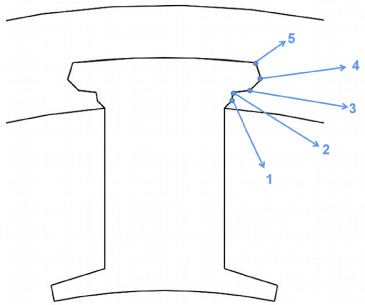
GO-NGO joint shape built based on piecewise linear interpolation method.
The point close to the stator’s inner side is determined as point 1. Among point 1 and point n, there are n-2 points are used to determine the joint shape. The distance between the points 1,2, …, n to the central point is R
1, R
2, … and R
n
, respectively. The angle between the stator tooth central line and lines o
1, o
2, …, and o
n
are A
1, A
2, …A
n
, respectively. where the central point is o, the parameters for different points meet the following relationship.
Through the qualitative analysis, both the electromagnetic and mechanical performance of the GO IPMSM are affected by the stator GO-NGO joint shape. However, it can be seen that both the average torque and torque ripple are almost independent of the GO-NGO stator joint shape by analyzing the electromagnetic performance. On the other hand, the GO-NGO stator joint shape has a great influence on the stress and strain in the joint part. Figure 4(a) shows the stress maximum and strain maximum corresponding to the different joint shapes, and the stator joint shape after the optimization is shown in Fig. 4(b). The stress maximum and strain maximum of the joint part of IPMSM corresponding to Fig. 4(b) are shown in Figs 4(c) and 4(d).
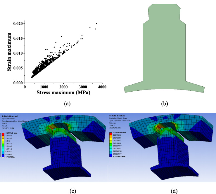
(a) Stress maximum and strain maximum corresponding to the different shapes. (b) Stator joint shape after the design optimization. (c) Stress maximum of contact part. (d) Strain maximum of contact part.
Figure 5(a) shows the electromagnetic torque waveform of NGO-IPMSM and GO-IPMSM under the current density of 18 A/mm2 and optimal phase angle of 37°, and the torque versus the current density comparison of these two machines is shown in Fig. 5(b). As shown, the average torque of GO-IPMSM is about 209 Nm, while the torque ripple is about 25% with the adoption of GO. The average torque of NGO-IPMSM is about 173 Nm, and the torque ripple is about 4.56%. Compared with NGO-IPMSM, the torque ability is improved by about 20.57%.

Torque comparison between NGO-IPMSM and GO-IPMSM. (a) Torque waveform, (b) Average torque versus current.
Figure 6(a) compares the core loss of these two machines when the torque is about 173 Nm. Figure 6(b) compares the efficiency versus the torque of these two machines under the same rotor speed of 3000 rpm. As shown, the core loss consumed in GO-IPMSM is about 264 W while that in NGO-IPMSM is about 289 W for achieving the same torque. With the GO adopted, the core loss can be reduced by about 8.56%. Moreover, the required current in GO-IPMSM is much lower. Therefore, the efficiency of GO-IPMSM is higher, especially in the high torque region.

(a) Core loss comparison between NGO-IPMSM and GO-IPMSM. (b) Efficiency comparison between NGO-IPMSM and GO-IPMSM.
With the adoption of GO designing the stator teeth of IPMSM, the torque ability can be improved while the core loss is reduced. However, the torque ripple is increased, which will bring the machine with big noise and high vibration. For the IPMSM, the rotor barrier shape affects the air gap flux density distribution and furthers the torque ripple. To reduce the torque ripple, optimizing the rotor barrier shape is an effective way. In this paper, the polynomial method is proposed to determine the rotor barrier shape, and the key parameters for controlling the rotor barrier shape are optimized by using the genetic algorithm. After the design optimization, the electromagnetic performance of GO-IPMSM before rotor barrier shape optimization and after rotor barrier shape optimization can be compared.
Rotor barrier shape determination
The irregular magnetic barriers are established symmetrical with the q-axis as the central line. The first magnetic barrier close to the air gap is determined by five curves, and the second magnetic barrier is determined by six curves as shown in Fig. 7(a). All these curves are determined by the following Eq. (4),

(a) Rotor structure determined by using the polynomial method. (b), (c), and (d) Different rotor structures are determined with different parameters.
The multi-layer design optimization algorithm is adopted for optimizing the rotor barrier structure as 46 parameters need to be optimized. Specifically, the parameters for determining the first rotor barrier were taken as the first group while those determining the second rotor barrier were taken as the second group [11,12]. Taking the average torque and torque ripple before optimization as the reference data, the optimization objective is defined as Eq. (5),
Specifically, the genetic algorithm is adopted for the optimization with the O 1 determined as the objective. During the optimization process, the magnetization direction of the PM is fixed while the shape changes with the rotor barrier changes. After design optimization, the shape of PM is not rectangular.
Figure 8(a) shows the optimized rotor structure of the GO-IPMSM. Figure 8(b) shows the electromagnetic torque waveform comparison between the GO-IPMSM before rotor barrier shape optimization and GO-IPMSM after rotor barrier shape optimization. With the adoption of the new rotor barrier shape, the average torque increases to 226 Nm, and the torque ripple reduces to 10.1%. Therefore, optimizing the rotor barrier is an effective way to improve the performance of the machine.
(a) Rotor structure after optimization. (b) Torque waveform comparison among GO-IPMSM before rotor barrier shape optimization, and GO-IPMSM after rotor barrier shape optimization.
For evaluating the performance of GO-IPMSM, both NGO-IPMSM and traditional NGO-IPMSM with 48 slots are employed as the benchmark machine. For a fair comparison, the rotor structure of GO-IPMSM, NGO-IPMSM, and NGO-IPMSM with 48 slots are all optimized.
Air gap flux density and PM flux linkage comparison
By using FEM, the air gap flux density and no-load PM flux linkage of these machines can be obtained as shown in Fig. 9. It can be seen that the radial air gap flux density can be increased with the adoption of GO replacing NGO in stator teeth. However, the impact on the no-load PM flux linkage is very low. Compared with NGO-IPMSM with 48 slots, though the air gap flux density magnitude of IPMSMs with 12 slots is higher, the no-load PM flux linkage magnitude is lower.

(a) Air gap flux density comparison. (b) No load PM flux linkage comparison.
The d-axis and q-axis flux linkages of IPMSM can be expressed by Eq. (6),
Since the flux linkage is nonlinear, the calculated electromagnetic torque based on Eq. (8) has some errors with that obtained by using FEM directly. The maximum error is within 8.7% under various operation states for GO-IPMSM while that for NGO-IPMSM with 48 slots is within 3.76%. Therefore, the inductance obtained is accurate in this paper.
Figure 10 shows the calculated d-axis and q-axis inductance versus the current density and current angle of these three machines. As shown, both the d-axis inductance and q-axis inductance are increased with GO adopted for IPMSM with 12 slots. While the d-axis inductance and q-axis inductance of the IPMSM with 48 slots are much higher, the main reason is that the stator teeth of IPMSM with 48 slots cannot be too fine, and the slot area of IPMSM with 48 slots is less than that of IPMSM with 12 slots. As shown, when the current density equals 18 A/mm2, the optimal phase angle for IPMSM with 12 slots and 48 slots are 37° and 53°, respectively. The corresponding saliency ratios of NGO-IPMSM, GO-IPMSM, and NGO-IPMSM with 48 slots are 0.74, 0.81, and 1.87, respectively.
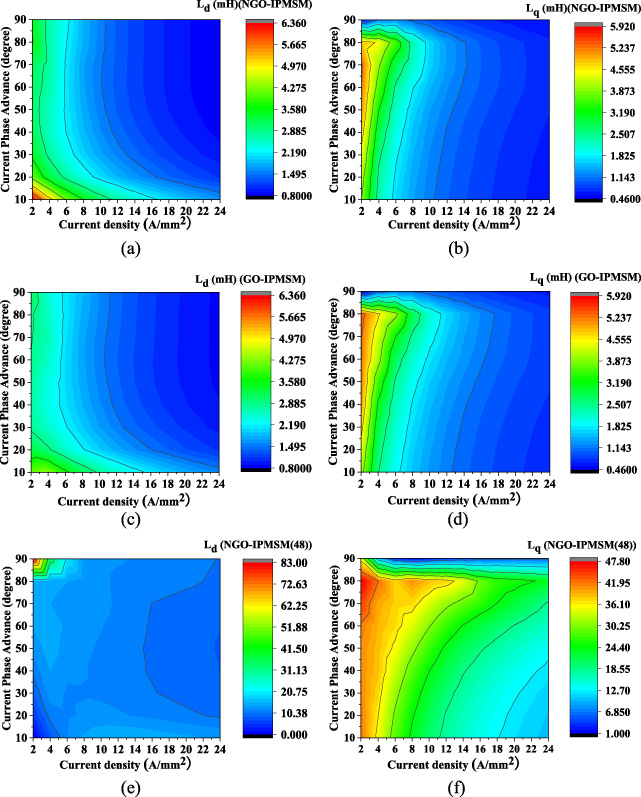
Calculated inductance comparison. (a) L d of NGO-IPMSM, (b) L q of NGO-IPMSM. (c) L d of GO-IPMSM, (d) L q of GO-IPMSM. (e) L d of NGO-IPMSM(48), (f) L q of NGO-IPMSM(48).
Figure 11 shows the calculated power factor of these machines. As shown, the power factor can be improved by using the GO replacing NGO in the stator teeth of IPMSM. Meanwhile compared with IPMSM with 12 slots, the power factor of NGO-IPMSM with 48 slots is much higher. The main reason is that the PM flux linkage of FSCW is low and the inductance of FSCW is high.
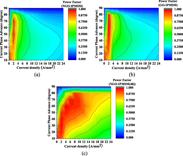
Calculated power factor comparison. (a) NGO-IPMSM, (b) GO-IPMSM, (c) NGO-IPMSM(48).
Figure 12(a) shows the torque waveform comparison of these machines when the current density equals 18 A/mm2 and a phase angle of 37° for GO-IPMSM and NGO-IPMSM and a phase angle of 53° for NGO-IPMSM with 48 slots. Figure 12(b) shows the average torque versus current density comparison, and Fig. 12(c) shows the average torque versus the phase angle comparison. As shown, compared with NGO-IPMSM, the torque ability of GO-IPMSM can be improved. Moreover, as the current density increases, the ratio of torque to current density decreases for the IPMSM with 12 stator slots.
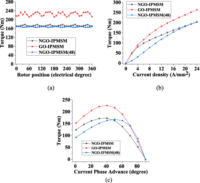
Torque comparison. (a) Torque waveform. (b) Average torque versus current. (c) Average torque versus current angle.
Efficiency map calculation method
Efficiency map is widely used for evaluating the operation performance of electrical machines. For obtaining an efficiency map, the efficiency of the machine under different rotor speeds and output torque needs to be calculated first. The efficiency can be calculated by Eq. (10),
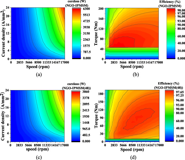
Core loss map and efficiency map comparison. (a) Core loss map of NGO-IPMSM. (b) Efficiency map of NGO-IPMSM. (c) Core loss map of NGO-IPMSM with 48 slots. (d) Efficiency map of NGO-IPMSM with 48 slots.
As the magnetic properties of the GO are anisotropic, the performance calculation time based on FEM is very long. Moreover, the required FEM samples are large for predicting the efficiency map. Therefore, it is important to predict the efficiency map quickly.
According to the Bertotti core loss separation theory, the core loss includes hysteresis loss, eddy current loss, and additional loss [15]. When the main magnetic flux changes in a sinusoidal way, the core loss can be calculated by Eq. (11),
As shown, the core loss depends on the magnitude and frequency of the flux density directly and the relationship is quite simple. While the magnetic flux works in the IPMSM is determined by the applied current excitation. Therefore, the core loss is transformed into a relationship between the excitation current and the rotor speed. Moreover, this relationship can be modeled by an approximate model. Compared with modeling the efficiency versus the excitation current and operation speed directly, the error for modeling the core loss is much lower. In this paper, the Kriging model is used to obtain the core loss map, and the efficiency is calculated as above.
The Kriging model is an interpolation model, which is defined as a linear weighting of the response value of the known sample function [16],
For the FEM sample selection, the Latin hypercube sampling method is used. Therefore, the sampling value can be ensured to cover the entire distribution area of the input random variable [16,17]. As shown in Fig. 14, 20 samples are obtained based on Latin hypercube sampling method. For efficiency map calculation by using traditional methods, 169 FEM samples are required.
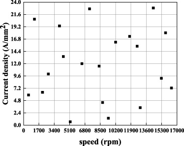
Diagram of FEM samples based on the Latin hypercube sampling method.
Figure 15 shows the core loss map and efficiency map of NGO-IPMSM with 12 slots and 48 slots based on the quick efficiency map calculation method, respectively. Comparing the efficiency map of NGO-IPMSM and NGO-IPMSM with 48 slots that were calculated by the traditional efficiency map calculation method and quick efficiency map calculation method as shown in Fig. 13 and Fig. 15, respectively. It can be seen that the average core loss errors for these two machines are 4.03% and 3.67%, while the average efficiency errors are 0.03% and 0.05%, respectively. Meanwhile, the main error occurs in the low-speed and low-current excitation region. Therefore, the quick efficiency map calculation method is effective for efficiency map prediction.
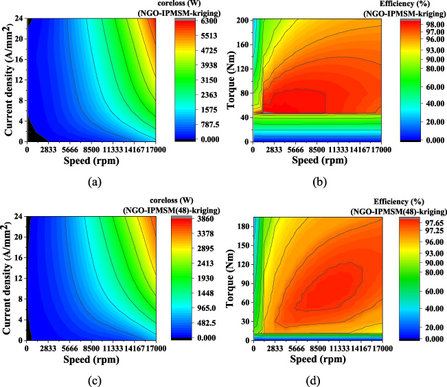
Calculated core loss and efficiency map based on quick efficiency map calculation method. (a) Core loss map of NGO-IPMSM. (b) Efficiency map of NGO-IPMSM. (c) Core loss map of NGO-IPMSM with 48 slots. (d) Efficiency map of NGO-IPMSM with 48 slots.
By using the quick efficiency map calculation method, the core loss and efficiency map of GO-IPMSM can be obtained as shown in Fig. 16. It can be seen that the operation efficiency of GO-IPMSM is slightly higher compared to the NGO-IPMSM.
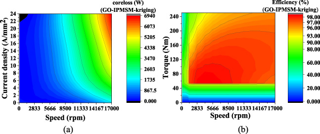
Calculated core loss and efficiency map of GO-IPMSM based on quick efficiency map calculation method. (a) Core loss map. (b) Efficiency map.
In this paper, the design and optimization of IPMSM with hybrid GO-NGO cores are presented. Considering the GO-NGO stator joint shape and the rotor barrier shape play a very important role in affecting the performance of GO-IPMSM, these above shapes are optimized by using the shape design optimization method. It can be seen that the mechanical performance is determined mainly by the GO-NGO stator joint shape, while the electromagnetic performance is independent of the GO-NGO stator joint shape. Meanwhile, the torque performance of GO-IPMSM can be improved greatly by optimizing the rotor barrier shape.
For evaluating the performance of GO-IPMSM, the NGO-IPMSM and IPMSM with 48 slots are both used as the benchmark machine. It can be seen that with the adoption of GO sheets, the GO-IPMSM has much better performance than the other machines. Moreover, the efficiency map of IPMSM can be obtained accurately and quickly by using the proposed quick efficiency map calculation method.
Footnotes
Acknowledgements
This work was supported by the National Natural Science Foundation of China under Grant 52377006 and 52007047, in part by the S&T Program of Hebei Province of China under Grant 225676163GH.