
Abstract
This paper proposes an electromagnetic damping generator (EDG), which is a novel downhole generator for the rotary steerable system (RSS). The EDG is designed to solve the problem of unstable voltage output by the RSS generator. The generator is designed by integrating a traditional generator and an eddy current retarder (ECR). The system converts the excess kinetic energy of the EDG rotor into heating energy by the principle of eddy-current braking and resistance heating. The electromagnetic finite element models of the generator part and ECR part are established and solved by computer. The voltage and torque generated by the generator part and the braking torque of the ECR part are predicted. In the bench test, When the input power is 2537 W < P input < 3304 W, the EDG is able to output 300.8 V. When the input power is 3304 W, the output voltage of the ordinary generator is 346 V. The EDG can be adjusted by a decrement of up to 45.2 V to output the rated voltage. The problem of generator output voltage instability in the RSS is solved when mud flow is unstable.
Introduction
Due to the great demand for quantities of oil resources and the increasing difficulty of mining in the world, the RSS is especially important [1–3]. At present, an RSS is mainly powered by generators or batteries [4]. The main advantage of using batteries is that they can produce a stable voltage. The disadvantages include (1) a short continuous working time (approximately 200 h) [5] and (2) environmental pollution. Generators that power an RSS not only operate continuously for a long time but also do not pollute the environment [6]. Batteries were gradually phased out after the application of generators to power RSSs. The flow of mud in the RSS varies greatly due to the geological structure being mined. Underground, the flowing mud provides power for the generator. The variation in the mud flow rate directly causes a variation in the generator output voltage [7]. When the generator output voltage exceeds the upper limit, the RSS is stopped by the protection circuit [8]. This greatly reduces the efficiency of oil extraction. Stable output voltage cannot be achieved only by the generator in the case of unstable mud flow.
Generators were invented in the 1830s and are divided into permanent magnet excitation generators and electric excitation generators according to the excitation mode [9]. Permanent magnet generators have the following advantages compared to electric excitation generators. (1) Permanent magnet generators, which are not fitted with excitation windings, collector rings or brushes, are simple in structure, reliable in operation and highly efficient. (2) The generator is significantly smaller and the power-to-mass ratio is significantly higher due to the use of permanent magnets for excitation. (3) The voltage regulation factor is smaller [10]. The permanent magnet generator is used in EDG based on the above advantages.
In 2011, Zhiming Wang proposed a hybrid excitation downhole turbine generator. It is based on a permanent magnet generator, and the output voltage is regulated by the electric excitation part. However, the rated output power of the generator is only 400 W, which cannot meet the requirements [11]. In 2013, Du Xiao proposed a new hybrid excitation generator for RSS. The generator outputs more than 2200 W of power and can adjust to within 24% of the rated voltage. The disadvantage is that the length reaches 465 mm [12]. Samarium cobalt (SmCo) magnets are commonly used in permanent magnet generators for RSS [13]. The maximum working temperature of the SmCo magnet is 350 °C. When the working temperature is above 180 °C, its maximum magnetic energy product (BHmax), coercivity, temperature stability and chemical stability are greater than those of the NdFeB permanent magnet material [14].
In 2016, Zhang’s patent of the invention of the downhole turbine generator was published. In this patent, the brake holding device is assembled to the generator shaft [15]. The shaft speed is reduced by friction when the output voltage is higher than the rated voltage. This results in a poor quality output voltage and the speed of rotation is difficult to quantitatively control in this way. In 2021, Yongjun Dong proposed a novel design of a horizontal-axis tidal stream energy generation system. Blades with symmetrical airfoils of the NACA series are employed to harvest the kinetic energy of the bidirectional tidal stream. To output stable power, the system is equipped with an adaptive variable-pitch turbine [16].
The ECR was invented in the 1930s and since then, many structural forms have been studied [17,18]. In 2014, the double salient pole ECR structure designed by Professor Li Desheng can cause the shaft to quantitatively decelerate by changing the current [19]. When the magnetic field is generated by a coil, ECR produces braking torque. When the rotor rotates with the drive shaft, the induction eddy currents generated by the convex pole of the rotor cutting the magnetic induction lines are produced on the inner surface of the stator. The stator applies electromagnetic torque to the rotor that opposes the rotational direction of the rotor, thereby reducing the speed of the shaft. At the same time, the eddy current flows inside the stator with a certain resistance, and the thermal effect of the resistance converts electrical energy into heat energy. In this way, the kinetic energy is eventually converted into heat energy by eddy current braking and resistance heating [20]. To restrain the thermal decay of ECR and improve the braking torque, many kinds of liquid-cooled ECR structures have been proposed [21,22]. In 2019, Guo Wenguang proposed a novel self-excited, liquid-cooled, and bridge-integrated retarder. It integrates the generator and ECR to overcome the large power consumption, braking torque heat recession, and installation difficulties for ECR trailers [23]. In 2019, Ye Lezhi applied generators and ECR to the energy recovery system of an electric bus, and the driving range was increased [24].
This paper proposes an electromagnetic damping generator (EDG), which is a novel downhole turbine generator for RSS. The EDG is composed of a generator and ECR coaxial assembly. The advantages of the EDG include a small axial length, high power generation, noncontact braking and quantitative regulation of the output voltage. After the EDG converts the excess kinetic energy of the rotor into thermal energy, which is carried away by the slurry and oil, the stable rated voltage is output. As a result, the EDG becomes a high-quality voltage source.
Structure & working principles
Structure
The structure of an ordinary turbine generator is shown in Fig. 1(a). The structure of the EDG is shown in Fig. 1(b). Due to space limitations, the EDG including the generator part and the ECR part is designed as a tube shape. The generator part is a permanent-magnet synchronous three-phase generator, which is designed in the left half, and the ECR part is designed in the right half. The ECR part is powered by the generator and regulated by the control circuit. The heat generated by the EDG is carried away by the oil contained inside the EDG and the mud contained outside [25].

Structure comparison.
The generator part, mainly including the generator stator, generator rotor and windings, is an internal-rotor permanent-magnet generator. The permanent magnet of the generator and the ECR rotor are assembled on the same shaft. The permanent magnets, being evenly embedded on the shaft surface, are encased in a stainless steel sleeve. There is a gap between the generator stator and the stainless steel sleeve.
The ECR part is a symmetrical structure, mainly including the ECR stator, ECR rotor, and coil. The braking torque that opposes rotor rotation is generated when the rotor teeth cut the magnetic lines of force on the inner surface of the stator. The ECR stator is a cylindrical structure. The coil is made of copper wire and is fixed to the inner wall of the stator. There is a gap between the rotor tooth top surface and stator inner wall. The shell is a magnetically conductive low-carbon steel, which helps to expand the magnetic circuit of the stator.
A high-speed rotating magnetic field is generated as the mud impinges on the turbine, causing the EDG rotor to turn together with the shaft. The kinetic energy is converted into electrical energy through the interaction between the rotating magnetic field and the three-phase winding. The torque balance equation of the EDG is:

The relationship of energy conversion.
According to Eq. (1) and the following formula:
The technical indicators table
The EDG supplies power to both the ECR part and the load. After the current in the ECR coil is increased through a control circuit, the output voltage is reduced to the rated voltage. The technical indicators of EDG are shown in Table 1.
When the load is a rated resistance, the load circuit is equated to a purely resistive circuit for the purpose of calculation. The power consumed by the load P
load of the load can be calculated by:
The loss power of the EDG P
loss includes the iron loss power P
Fe of the yoke, the copper loss power P
Cu of the winding, the mechanical loss power P
f and the stray loss power P
s. The loss power of the EDG P
loss can be calculated by:
The ECR coil is considered a purely resistive circuit for calculation. The rectified voltage U
load is adjusted by the control circuit and converted into the DC voltage U
H at both ends of the ECR coil. The heating power of ECR coil P
H can be calculated by:
The magnetic induction lines generated by the coil are cut by the ECR rotor, causing induced eddy currents, which in turn cause a corresponding induced magnetomotive force to be generated on the inner surface of the stator. The original main magnetic field is affected by the induced magnetomotive force when the ECR part is working. Therefore, the air-gap magnetic field during ECR part operation is a superposition of the induced magnetic field generated by the eddy currents and the original main magnetic field. The synthetic flux density B
δ
in the air gap is obtained from the flux density B
0 generated by the coil and the flux density B
i generated by the eddy current.
The power generated by the eddy current braking P
B can be calculated by:
Generator part
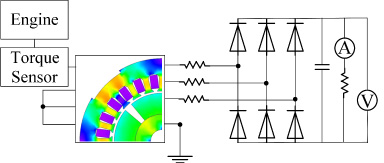
The generator simulation model consists of a geometric model and a circuit model, as shown in Fig. 3. The geometric model includes the generator stator, windings, permanent magnets and generator rotor. The circuit model includes an engine, torque and speed sensor, three-phase resistor, and a rectifier bridge consisting of six diodes, filter capacitor, load resistor, ammeter, and voltmeter. It is assumed that the cross-section shape of the generator is the same and the end effect is ignored. To save computer computing time and running space, a two-dimensional
The finite element analysis model of the generator part.
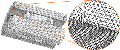
Meshing grid.

One quarter of the ECR model.
The finite element method is the most widely used and effective method at present. In previous studies, the results of ECR analysis by the finite element method are close to the experimental results. The ECR stator and shell are combined in the finite element model because both are made of low carbon steel. Since the ECR part is circularly symmetric in the circumferential direction, one quarter of the ECR model is calculated by Jmag. Since eddy current and braking torque are generated on the inner surface of the stator, the grid at this position is refined to 1 mm for accurate calculation [29], as shown in Fig. 4. The magnetic flux density is greater at the top of the rotor teeth. The braking performance of the ECR is improved due to the aggregation of the magnetic field by the tooth structure. The optimized ECR finite element model is obtained using the scanning parameter method [30], as shown in Fig. 5.
Experiment
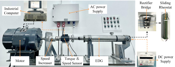
The test bench.
Bench test photos are shown in Fig. 6. The experimental device consists of an AC power supply, motor, speed increaser, torque and speed sensor, EDG, adjustable DC power supply, rectifier bridge, sliding rheostat and industrial computer. In the bench test, the motor is supplied by an AC power supply. The motor drives the rotation of the EDG rotor. The torque generated by the EDG and the speed of the EDG rotor are measured by a torque and speed sensor. The adjustable DC power supply and the rectifier bridge replace the control circuit to supply power to the ECR part and load, respectively. The braking torque of the ECR part T ECR is controlled through the adjustable DC power supply. The industrial computer can not only control the speed of the motor but can also measure the torque value and speed value of the EDG.
Generation performance of the generator part

The torque of the generator part at different speeds.
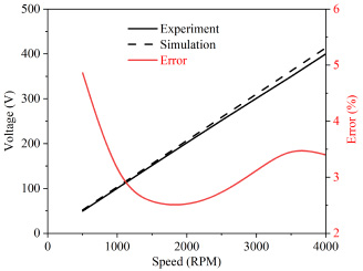
The voltage of the generator part at different speeds.
When the load of the EDG is rated (37.5 Ω) and the ECR part is not working, the torque and the output voltage of the EDG increase linearly with the speed, as shown in Figs 7 and 8. Input power P
G when the ECR part is not working:

The generation efficiency of the generator part at different speeds.
Thus, the generation efficiency of EDG is:
When the EDG is unloaded, the ampere-turns are 0–3000, and the speed is 2800 RPM–4000 RPM. The simulation value of the braking torque is shown in Fig. 10, and the experimental value is shown in Fig. 11. As shown in Figs 10 and 11, there is little difference between the experimental data and simulation data. In the above range, the torque increases with the ampere-turns and speed.
In the experiments, the coil chosen was required to have a safe current of less than 1 A. Due to the limitation of the ECR coil installation space, the theoretical number of coil turns is 3186, but the actual number is 2560. Therefore, the maximum number of ampere-turns of the coil is 2560. When the speed is 3000 RPM, the curve of the braking torque with ampere-turns is shown in Fig. 12. The growth rate of torque increases first and then decreases with the ampere-turns. The finite element calculation method was shown to be correct by comparing the error between the simulated and experimental values, which was less than 1%. When the number of ampere-turns is 2560 and the speed is 3000 RPM, the braking torque in the ECR part increases less after reaching 2.04 Nm. This indicates that when the number of ampere-turns reaches 3000, the magnetic field in the stator and rotor of the ECR part almost reaches saturation. According to formula (2), the maximum braking power generated by ECR partial braking is 641 W at 3000 RPM.

Simulation torque of the ECR part at different speeds and ampere-turns.
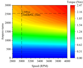
The experimental torque of the ECR part at different speeds and ampere-turns.

Torque of the ECR part at 3000 RPM and different ampere-turns.
The maximum temperature in the underground environment is 150 °C [27], and the oil in EDG is heated to 200 °C [31]. To obtain the heating characteristics of the ECR coil at 200 °C, an adjustable DC power supply, two digital multimeters and an ECR coil are used to build the circuit, as shown in Fig. 13. In the bench test, the ECR coil is heated by a DC power supply. According to formula (16), when the ECR coil is heated to 200 °C at a room temperature of 0 °C, the resistance value increases by a factor of 0.8.

The experimental circuit for ECR coil heating.
According to formula (17), when the resistance of the ECR coil increases from 70 Ω to 126 Ω, the temperature of the ECR coil increases from 0 °C to 200 °C.

The heating power of the ECR coil at different ampere-turns.
P G/P load/P loss at different speeds.
Power characteristics of the generator part
According to Figs 7, 8, 9 and formula ((2)), when the ECR part is not working, the output power of EDG P G, the power consumed by the load P load and the loss power of the EDG P loss increase with speed (500 RPM–4000 RPM) in a squared relationship, as shown in Fig. 15. The output power of the EDG P G is synthesized from the power consumed by the load P load and the loss power of the EDG P loss.

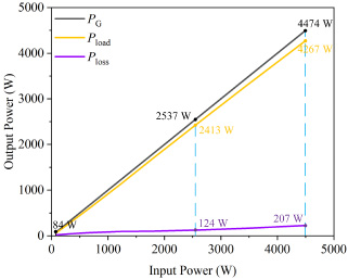
P G/P load/P loss at different P input.

The P ECR/P B/P H at different ampere-turns and 3000 RPM.
The characteristics change table
Based on Fig. 15 and the energy conservation law, as the speed increases from 500 RPM to 4000 RPM, the output power of the EDG P G, the power consumed by the load P load and the loss power of the EDG P loss increase linearly with the input power P input, as shown in Fig. 16. When the ECR part is not working, the output power P G (including P load, P loss), speed and output voltage of the EDG vary with the input power P input, as shown in Table 2. When the input power P input reaches 2537 W and the speed reaches 3000 RPM, the output power of the EDG P G is 2537 W, including 2413 W (P load) and 124 W (P loss). When the input power P input reaches 4474 W and the speed reaches 4000 RPM, the output power of the EDG P G is 4474 W, including 4267 W (P load) and 207 W (P loss).
From Figs 12, 14, and formula (2), the relationship between the power of the ECR part P ECR, the power generated by eddy current braking P B, and the power generated by ECR coil heating P H and ampere-turns is deduced, as shown in Fig. 17. The power of the ECR part of the P ECR is synthesized from the power generated by eddy current braking P B and the power generated by ECR coil heating P H. The growth rate of the power of the ECR part of the P ECR and the power generated by eddy current braking P B increase and then decrease as the number of ampere-turns increases. The power generated by ECR coil heating P H increases with the number of ampere-turns in a squared relationship.

The P ECR/P B/P H at different P input and 3000 RPM.
According to Figs 16, 17, and the energy conservation law, the relationship between the power of the ECR part P ECR, the power generated by eddy current braking P B, the power generated by the ECR coil heating P H and the input power P input is shown in Fig. 18. Because the upper limit of the current in the ECR coil is 1 A, the maximum number of ampere-turns is 2560. As the number of ampere-turns in the ECR coil increases from 0 to 2560, the input power P input increases from 2537 W to 3304 W. When the input power is 2537 W < P input < 3304 W, the speed of the EDG rotor remains constant at 3000 RPM, and the output voltage remains constant at 300 V under the action of the ECR. When the input power P input reaches 3304 W, the ECR part reaches the upper limit of adjustable power (767 W), including P B (641 W) and P H (126 W). As the input power P input increases, the power generated by eddy current braking P B decreases, but the rate of increase of the power generated by ECR coil heating P H increases.

The T B at different speeds.
The P B at different speeds.
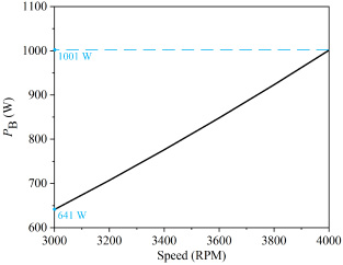
When P input > 3304 W and speed > 3000 RPM, the ECR works at full power. Based on Fig. 11, when the number of ampere-turns of the ECR coil is 2560 and the speed increases from 3000 RPM to 4000 RPM, the torque due to eddy currents in the ECR T B increases linearly with the speed, as shown in Fig. 19. The torque due to eddy currents in the ECR T B increased from 2.04 Nm to 2.39 Nm.
From Fig. 19 and formula (2), the power generated by eddy current braking P B increases linearly with the speed, as shown in Fig. 20. The power generated by eddy current braking P B increased from 641 W to 1001 W. The current in the ECR coil reaches the upper limit (1 A). Therefore, as the input power increases, the power generated by the ECR coil heating P H remains constant at 126 W. According to Figs 16, 18, 20 and the energy conservation law, when the input power P input increases from 3304 W to 5601 W, the power generated by eddy current braking P B increases linearly with the input power P input, as shown in Fig. 21.
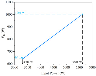
The P B at different P input.
In summary, the maximum power that can be adjusted by the ECR part is P ECR = P B + P H = 767 W at 3000 RPM, and the maximum power that the EDG can produce is P EDG = P G + P ECR = 3304 W. That is, the EDG can adjust the output voltage to the rated voltage (300 V) when the input power is 2537 W < P input < 3304 W. When the load equals the rated load (37.5 Ω) and the speed increases from 500 RPM to 4000 RPM, the output power of EDG P output increases from 84 W to 5601 W. Based on Figs 16, 18 and 21, the output power of the EDG P output (including P load, P lost, P B and P H) varies with the input power (84 W < P input < 5601 W)), as shown in Fig. 22 and Table 3.
Comparison of the generation characteristics between the ordinary generator and the EDG
In the bench test, when the input power P input increases from 2000 W to 4000 W, the change in the output voltage of the EDG with the input power P input under the two states of ECR, working or not, is shown in Fig. 23. The change in the EDG output voltage in Fig. 23 is verified by Fig. 22 and formula (3). When the ECR part is not working, the EDG is regarded as an ordinary generator. The difference between an ordinary generator and EDG generation characteristics can be shown in Fig. 23. The output voltage of the EDG remains constant at 300.8 V when the input power P input is between 2537 W and 3304 W. When the input power exceeds this range, the output voltage of the EDG increases with increasing input power P input. However, the output voltage of an ordinary generator increases with increasing input power P input when the input power P input is between 2000 W and 4000 W. When the input power P input is 3304 W, the output voltage of the ordinary generator is 346 V, and the output voltage of the EDG is 300.8 V. This shows that EDG can reduce the voltage at most by 45.2 V.

The output power at different values of input power.

The output voltage of the ordinary generator and the EDG.
The power change table
This paper reports the study and design of an electromagnetic damping generator (EDG), which is a novel generator for a RSS. Combined with the ability of an ECR to suppress the speed of the EDG rotor, an EDG structure for a stable output voltage is proposed. The EDG converts kinetic energy into electrical energy and heating energy by the principle of electromagnetic induction, eddy-current braking and heating. The structure of the EDG is designed, and mathematical models of generation efficiency and heating are established. According to the simulation results, an EDG prototype was fabricated, and the bench-scale experimental results were measured. To verify the performance of the EDG, the power generation performance of the generator part was tested, and the braking performance and heating performance of the ECR part were tested.
After comparing the experimental value with the simulation value, the power generation characteristics of the EDG were analysed. When 2537 W < P input < 3304 W, the output voltage is adjusted to 300.8 V by EDG. The maximum voltage adjustment by the EDG is 45.2 V. The EDG effectively solves the problem of excessive output voltage from the RSS generator when the mud flow is excessive. This paper describes the feasibility and advantages of the idea of integrating the ECR and the generator.
The power generated by ECR coil heating P H increases with an increasing number of ampere-turns in a square relationship. Therefore, the increase in ampere-turns will significantly improve the ability of EDG to adjust the output voltage. In the future, the influence of temperature on the inside of the EDG and the current tolerance limit of the ECR coil need to be studied. At present, the generation characteristics of the EDG have been deeply analysed, research on EDG control systems will be carried out, and the quality of the output voltage will be further improved.
Footnotes
Acknowledgement
The authors would like to thank the National Natural Science Foundation of China [No. 51777003] and the Natural Science Foundation of Beijing, China [Project No. 3212028] for funding this work.