
Abstract
Permanent magnet-assisted synchronous reluctance motor (PMSRM) has been widely used in many fields due to their advantages of less permanent magnets and low cost. However, the permanent magnet torque and reluctance torque of the traditional PMSRM reach their maximum values at different current angles. Therefore, the utilization ratio of the total torque to each torque component is low, which leads to the low power density of the PMSRM. To solve this problem, a new rotor structure suitable for PMSRM is proposed in this paper. The rotor can improve the total torque by increasing the maximum value of permanent magnet torque and the utilization rate of total torque to each torque component. Thus, the power density of the motor is effectively improved. In order to realize the matching design of each parameter in the proposed rotor structure, the Taguchi method is used to optimize the design, and the influence of each optimization variable on torque and torque ripple is analyzed. The finite element simulation analysis method is used to establish the electromagnetic simulation model of the traditional structure, the new structure proposed and the optimized structure of the new structure by Maxwell simulation software. The simulation results show that the proposed new rotor structure not only effectively improves the torque density, but also effectively reduces the torque ripple.
Introduction
Permanent magnet synchronous motor (PMSM) is widely used in many fields such as electric vehicles [1], aerospace [2] and industrial production [3] due to their remarkable advantages of small size, low loss and high efficiency. However, PMSMs need to consume a large amount of rare earth permanent magnet materials, which lead to high cost and unstable supply [4]. In order to solve such problems, PMSRM with less permanent magnets have attracted widespread attention [5]. The torque of the PMSRM is composed of two aspects: one is the permanent magnet torque, and the other is the reluctance torque generated by the different inductances of d-q axis. Due to the low permanent magnet torque of PMSRM and the low utilization of the total torque to each torque component, the power density of traditional PMSRM is low.
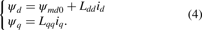
In order to improve the power density of PMSRM, on the one hand, it can be achieved by increasing the maximum value of each torque component of the motor. In [6], magnetic flux leakage is reduced and permanent magnet torque is increased by changing magnetization direction of permanent magnet. But it is difficult to change magnetization direction of permanent magnet. In [7], the third harmonic current is injected into the stator current. Then the permanent magnet torque is improved by utilizing the third harmonic of the rotor magnetomotive force of the dual three-phase PMSM. Literature [8] monitors magnetic field by installing hall sensors in each phase winding. Then the current that can change with the magnetic field is introduced into the stator winding. And certain harmonic orders of magnetomotive force can be utilized to increase the permanent magnet torque. But this method will make the motor control system more complicated. Reference [9] increases the salient pole ratio of the motor by changing the shape of the rotor magnetic barrier. Thereby the reluctance torque and torque density can be improved. Similarly, the reference [10] increases the salient pole ratio of the motor by adding a magnetic barrier at the pole shoe of the salient pole rotor. Thereby the reluctance torque is improved.
In addition, the power density of the motor can be improved by increasing the utilization ratio of the total torque to each torque component. Reference [11] first proposes an asymmetric rotor structure in which magnetic barriers are added beside permanent magnets. The maximum axis of reluctance torque is offset by this structure, so the utilization ratio of total torque to each torque component is improved. However, the existence of magnetic barriers also reduces the maximum value of reluctance torque. Therefore, literature [12] proposes an asymmetric rotor structure with an irregular arc magnetic barrier beside the permanent magnet. This structure leads the magnetic lines to pass through the rotor core, so that the reluctance torque remains unchanged during the offset process. Obtaining the same average torque with less permanent magnet is realized. However, there are difficulties in manufacturing the rotor structure. In [13,14], the utilization rate of torque is improved by changing the position of permanent magnets and adding magnetic barriers beside permanent magnets. Further, literature [15] analyzes the relationships between the permanent magnet offset angle, magnetic barrier angle and the torque component utilization of the motor in [14]. The utilization ratio of total torque to each torque component is improved by selecting the optimal angle. But the relative position of interior permanent magnet and embedded permanent magnet is limited. Therefore, in reference [16], two kinds of rotors are combined axially at an appropriate angle to improve the utilization ratio of total torque to each torque component. One kind of rotor is a surface-mounted rotor that only provides permanent magnet torque. Another kind of rotor is a reluctance rotor that only provides reluctance torque. However, the total torque is only increased by 7%, which is not ideal. Similarly, the axial rotor structure of the motor in [17] is the reluctance rotor, the surface-mounted rotor and the reluctance rotor in sequence. The utilization rate of each torque component is improved by combining three segmented rotors at specific assembly angle. But the increase of torque is also insignificant, only increased by 5.5%. Literature [18] proposes an asymmetric rotor structure to improve the utilization rate of each torque component by placing the permanent magnets asymmetrically without changing the magnetic barrier structure. However, this method is only suitable for special rotor structure.
When optimizing each parameter of the motor, not only is the interaction effect between multiple optimization variables necessary to be considered, but also different performances of the motor need to be taken into account. Therefore, the multi-objective optimization design method is generally adopted. Currently, the commonly used multi-objective optimization design methods mainly include genetic algorithm [19], immune algorithm [20] and optimization algorithm based on particle swarm optimization [21]. However, the above intelligent optimization algorithms have problems such as complex solution process and long solution time. Correspondingly, the Taguchi method established by Dr. Genichi Taguchi from Japan is a low-cost and high-efficiency multi-objective optimization design method and evolved by enterprises to process low-cost and high-quality products. This method considers its robustness in the production process of products, which in turn allows for high-quality products to be produced. This method can guide multi-objective optimization through limited orthogonal experiment data, thus reducing the number of experiments substantially, lowering the cost of the experiments, finding the optimal parameter combinations at the fastest speed, and improving the efficiency of the design. In [22], Taguchi method is used to optimize the parameters of reluctance motor. Then the no-load back EMF of the motor is closer to sine and the cogging torque is lower. Similarly, Taguchi method is used in [23] to optimize the position of permanent magnets to improve the average torque, torque ripple and efficiency of the motor. Reference [24] also optimizes the stator structure of the motor through the Taguchi method, which improves the motor efficiency. In the process of using the Taguchi method to optimize the design, it is necessary to analyze the simulation results of the orthogonal experiment. The average value and variance analysis for the simulation results of the orthogonal experiment are usually analyzed by statistical methods. Reference [25] adopts Taguchi method to optimize the motor structure in order to improve the efficiency of permanent magnet synchronous motors and reduce the cogging torque. The optimal combination was determined by analyzing the average value and variance of the results. Reference [26] takes the main characteristics such as induced electromotive force as the optimization objective, optimizes the air-core axial flux permanent magnet generator by the Taguchi method. The optimum combination of optimized variables is obtained using average value analysis and variance analysis.
In order to improve the power density of PMSRM, a relatively simple and general new rotor structure is proposed in this paper. By converting the outermost interior I-shaped permanent magnet into an embedded arc-shaped permanent magnet, the leakage flux is reduced. Thereby the maximum value of the permanent magnet torque is increased. In addition, the offset of the permanent magnet torque is achieved by asymmetrically placing the permanent magnets under each pole. Therefore, the current angle difference between the maximum value of permanent magnet torque and the maximum value of reluctance torque is reduced. And then the utilization ratio of total torque to each torque component is improved. On this basis, the key parameters in the proposed rotor structure are optimized by using Taguchi method. By analyzing the influence and relative importance of each optimization variable on torque and torque ripple, a high power density PMSRM design scheme with low torque ripple is obtained.
High power density PMSRM design
In this section, the traditional structure of PMSRM is described and the mathematical expression of its torque is derived. On this basis, an improved structure of the motor is proposed. The feasibility of the proposed structure in improving the power density of the motor is theoretically analyzed. And the effectiveness of the proposed improved structure is verified by finite element simulation.
Structure and parameters of traditional PMSRM
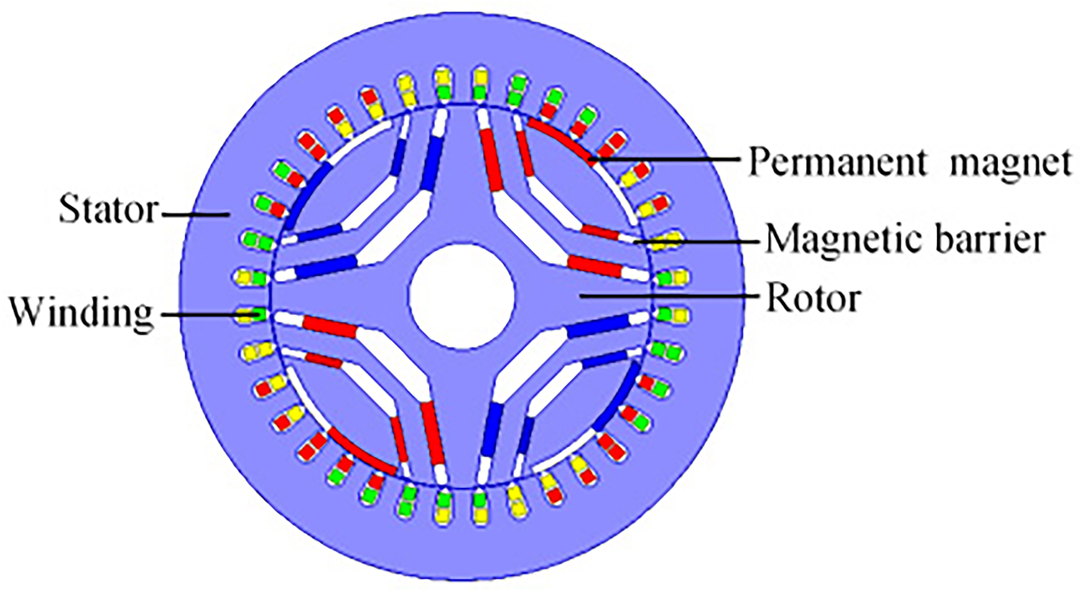
This paper takes a 20 kW, 4-pole 36-slot PMSRM as the research object. The motor structure is shown in Figure 1, and the rotor has three layers of magnetic barriers. The outermost permanent magnet is located in the middle of I-shaped magnetic barrier. And the two inner layers of permanent magnets are located in the middle of the U-shaped magnetic barrier. The stator winding adopts distributed short-pitch windings. The specific parameters of the motor are shown in Table 1.
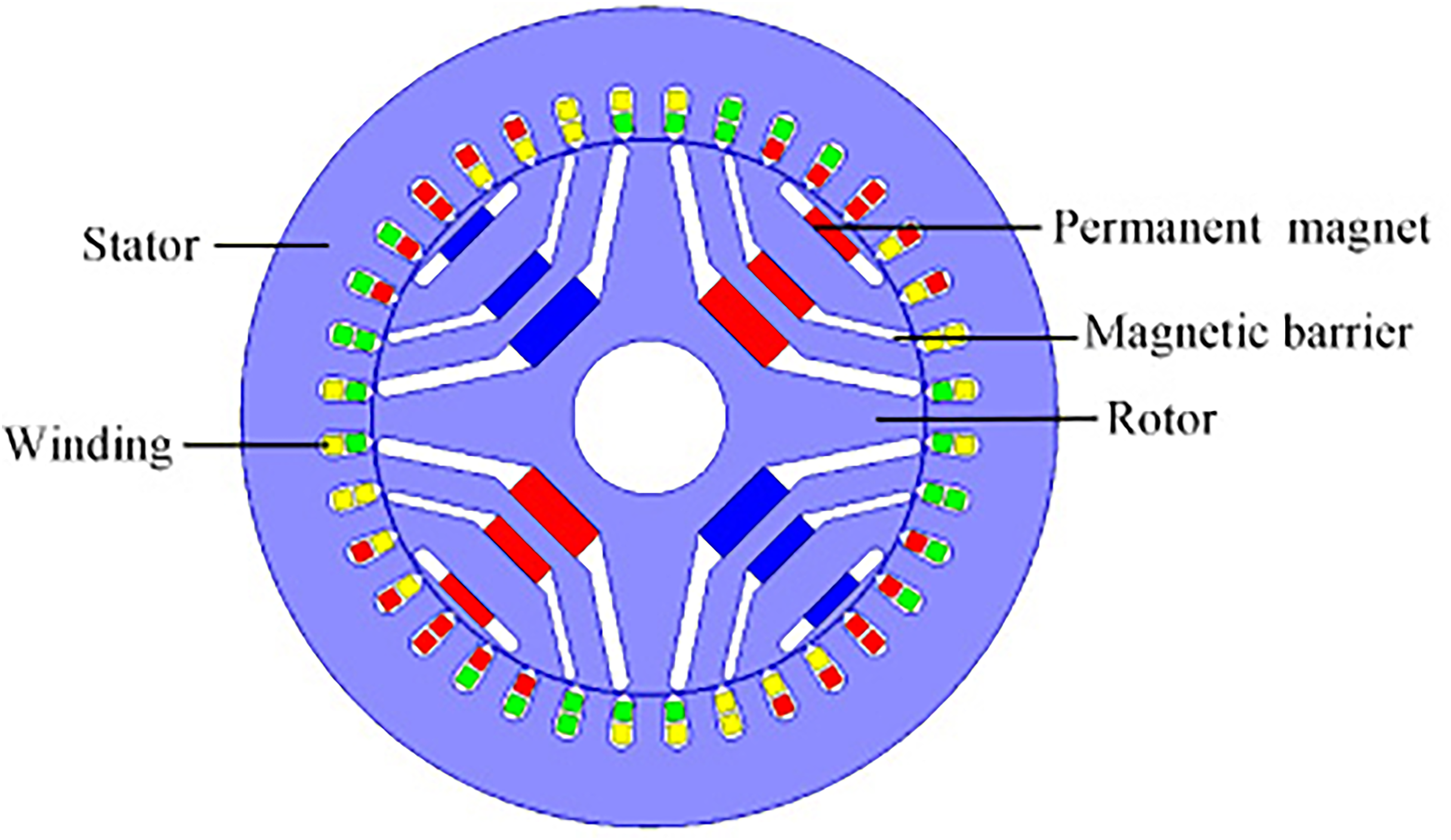
Motor structure.
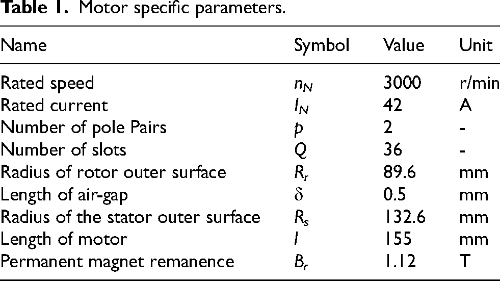
Motor specific parameters.
The power density of the motor can be improved by reducing the volume of the motor and increasing the output power of the motor. However, reducing the volume of the motor will inevitably deteriorate the heat dissipation ability of the motor, which brings a series of adverse effects such as large motor loss and poor load capacity. Therefore, in this paper, the output power of the motor is improved under the condition of ensuring that the volume of the motor remains unchanged, and the specific relationship between the power P and torque T is as follows:
From Eq. (1), it can be seen that the output power of the motor can be improved by increasing the torque of the motor under the condition that the speed of the rotor in the motor is constant. Therefore, the subsequent theoretical analysis of the torque of the motor is mainly carried out to find out the design method for improving the torque from the root.
In order to facilitate the analysis, the ABC-axis is converted to the dq-axis with the constant power as the constraint. The stator current conversion relationship is as follows
The d-axis current i
d
and q-axis current i
q
can be obtained by decomposing i
s
. The specific relationship is as follows
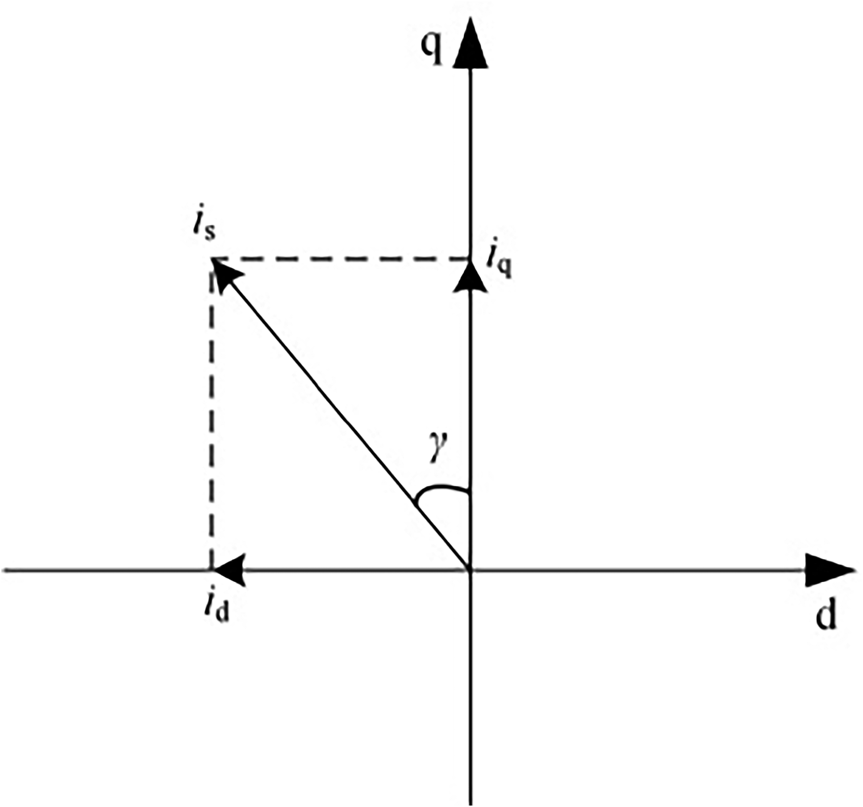
d-q axis coordinate system.
Further, the expression of permanent magnet torque T
pm
can be obtained
Similarly, the expression of the reluctance torque T
re
is as follows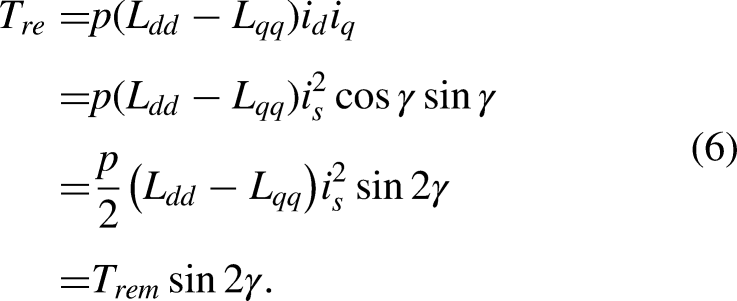
Finally, the total torque T can be expressed as follows
According to Eqs (5)∼(7), the torque waveforms shown in Figure 3 can be obtained. In the figure, the total torque, permanent magnet torque and reluctance torque are represented by T, T pm and T re . It can be found that the variation frequency of reluctance torque with current angle is twice that of the permanent magnet torque with the current angle. That is, there is a double frequency relationship between the reluctance torque and permanent magnet torque. Therefore, in the traditional symmetrical rotor structure, the difference between two current angles corresponding to the maximum value of the reluctance torque and the maximum value of the permanent magnet torque is 45°. Hence, the maximum value of the total torque is smaller than the algebraic sum of the maximum values of two torque components.
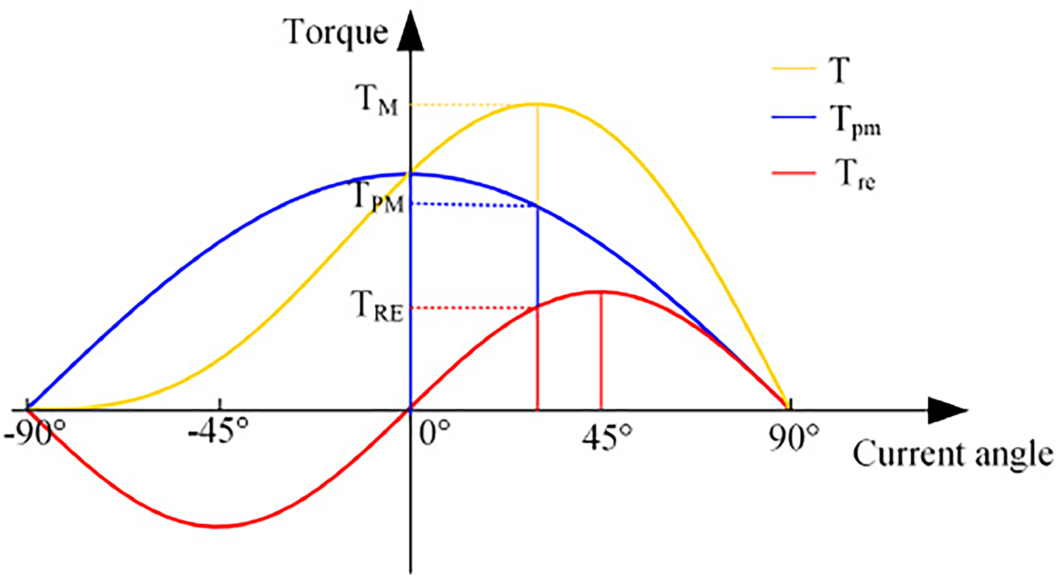
Torque waveforms.
In order to explain the relative positions of the reluctance torque and the permanent magnet torque more conveniently, the utilization ratio of permanent magnet torque k
PM
and reluctance torque k
RE
are introduced, and their specific form are as follows
In order to improve the utilization ratio of total torque to each torque component, the rotor magnetic barrier structure and permanent magnet placement position can be designed to be asymmetrical. On the one hand, asymmetric arrangement of permanent magnets under each pole can change the direction of flux lines generated by permanent magnets. Hence, the axis corresponding to the maximum value of permanent magnet torque can be deviated. If the axis shifts to the direction of the maximum value of reluctance torque by α electrical angle, the permanent magnet torque changes from Eq. (5) to Eq. (9). On the other hand, by adding asymmetric magnetic barriers between the magnetic poles of the rotor, the direction of the flux lines generated by the armature current can be changed. Therefore, the axis corresponding to the maximum value of reluctance torque can be shifted. If the axis shifts to the direction of the maximum value of permanent magnet torque by β electrical angle, the reluctance torque can be changed from Eq. (6) to Eq. (10).

According to Eqs (5)∼(10), the torque waveforms before and after shifting each torque component are obtained, as shown in Figure 4. In the figure, the torque waveforms corresponding to the traditional structure are T1, Tpm1, and Tre1. Correspondingly, the torque waveforms after shifting each torque component are T2, Tpm2, and Tre2. It can be seen from Figure 4 that the maximum value of total torque can be effectively improved by reducing the difference between the current angles corresponding to the maximum values of two torque components. Theoretically, the permanent magnet torque and the reluctance torque can reach their maximum values at the same current angle by designing the appropriate α and β. At this time, the maximum value of the total torque is the maximum.
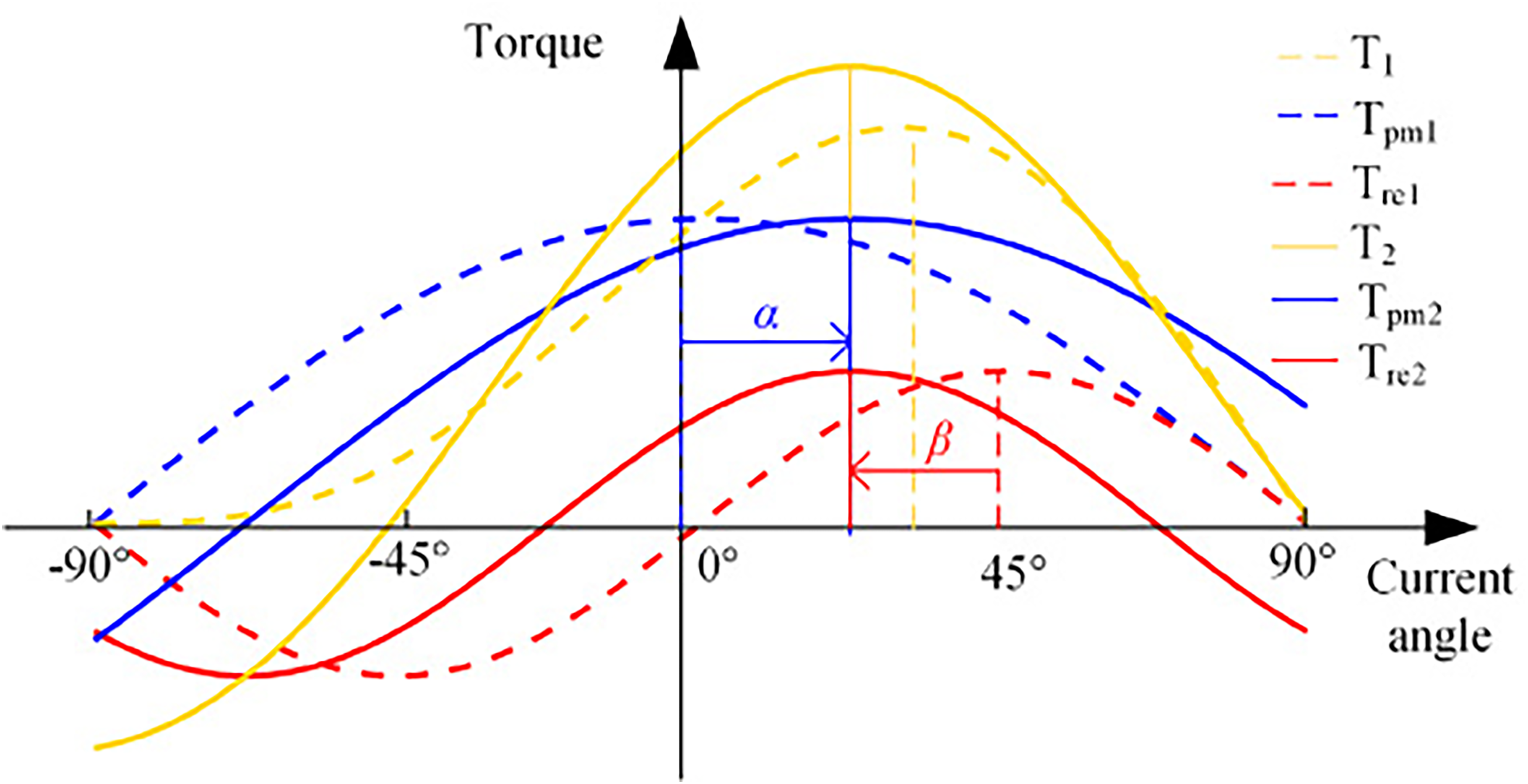
Torque waveforms comparison.
In order to improve the power density, this paper improves the traditional symmetrical rotor structure from the following two aspects. On the one hand, in order to increase the maximum value of the permanent magnet torque, the interior I-shaped permanent magnet in the outermost layer under each magnetic pole is changed to an arc-shaped embedded permanent magnet. Thereby, the magnetic flux leakage of the permanent magnet is reduced. On the other hand, in order to reduce the differences between current angles corresponding to the maximum values of two torque components, the embedded permanent magnet under each pole is asymmetrically placed on the side of the arc magnetic barrier. At the same time, the I-shaped permanent magnet in the middle of the U-shaped magnetic barrier is asymmetrically placed to both sides of the U-shaped magnetic barrier. In this way, the offset of the permanent magnet torque is realized, and the utilization rate of the total torque to each torque component is improved. The improved rotor structure is shown in Figure 5.

Improved motor structure.
The maximum value and utilization rate of each torque component can be obtained by decomposing the total torque corresponding to the traditional rotor structure and improved rotor structure. The waveforms of the total torque and each torque component are shown in Figure 6. In the figure, the waveforms of the total torque, permanent magnet torque and reluctance torque corresponding to the traditional rotor structure are T1, Tpm1 and Tre1. Accordingly, the waveforms of the total torque, permanent magnet torque and reluctance torque corresponding to the improved rotor structure are T2, Tpm2 and Tre2. It can be seen from Figure 6 that the maximum value of the permanent magnet torque becomes larger and its waveform shifts 18.5° to the direction of the maximum value of the reluctance torque. The maximum value of the reluctance torque decreases after the pole shift. The reason is that the arc-shaped magnetic barrier obstructs the magnetic line flow path and the change in the size of the outermost permanent magnet affects the magnetic line flow path. However, the waveform of reluctance torque does not shift. Therefore, the difference between the current angles corresponding to the maximum values of two torque components is reduced from 45° to 26.5°, which improves the utilization rate of the total torque to each torque component. Finally, the maximum value of total torque is increased, as shown in Table 2.
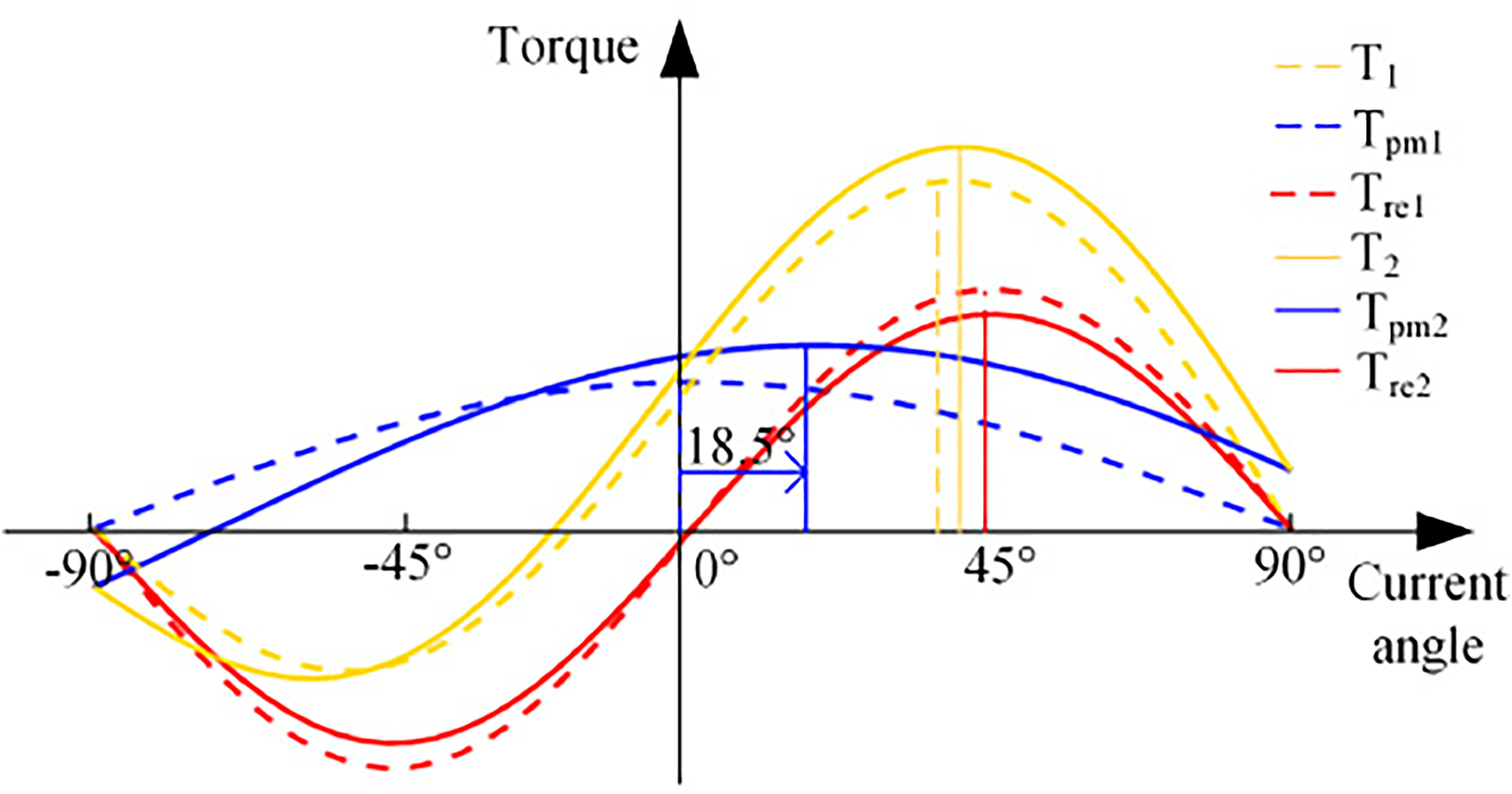
Torque waveforms comparison.
Specific data comparison.
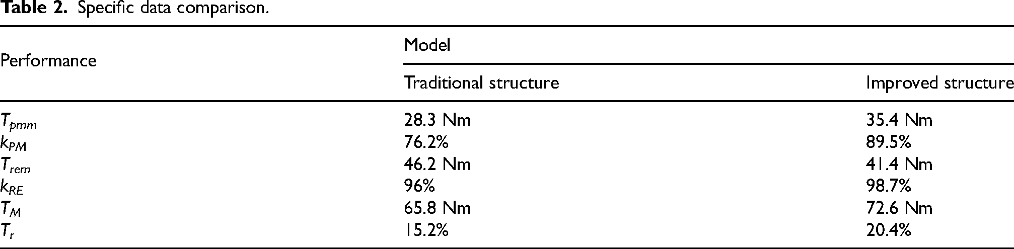
As can be seen from Table 2, the maximum value of permanent magnet torque T pmm increases by 25.1% after adopting the improved rotor structure. Due to the asymmetric placement of the permanent magnets under each pole, the permanent magnet torque is offset. As a result, the permanent magnet torque utilization k PM increases by 17.5%, and the reluctance torque utilization k RE increases by 3%. The increase of the maximum value of permanent magnet torque T pmm and the offset of the permanent magnet torque axis make the total torque T increase by 10.3%. But at the same time, the torque ripple T r also increases from 15.2% to 20.4%. The main reason is that the key parameters in the improved rotor structure do not achieve the best matching. Therefore, it is necessary to further optimize the improved rotor structure to make average torque large and the torque ripple small.
This section mainly adopts the Taguchi method to optimize the proposed improved rotor structure. The matching design of key structural parameters in the improved rotor structure is realized by analyzing the influence and relative importance of each optimization variable on torque and torque ripple.
Selection of optimization variables, optimization objectives and constraints
The optimization variables are determined according to the proposed improved rotor structure, as shown in Figure 7. The design idea of this paper is to ensure that the position of the reluctance torque waveform remains unchanged. The permanent magnet torque is derived from the permanent magnet, therefore, in order to achieve the offset of the permanent magnet torque, an asymmetric design of the permanent magnet is proposed. The paper determined the optimization variables according to the proposed improved structure, that is, the selected optimization variables can uniquely determine the improved structure. In order to facilitate the description of optimization variables, the permanent magnets under one pole are named as 1∼5, and the lengths of permanent magnets from 2∼5 are l2∼l5. The optimization variables are selected as follows: variable A is the angle between the downside of permanent magnet 1 and the positive direction of X-axis. Variable B is the angle between the upside of permanent magnet 1 and the positive direction of X-axis. Variable C is the length of permanent magnet 2. Variable D is the difference between the lengths of permanent magnets 2 and 3, as shown in Eq. (11). The relation between variable E and the lengths of permanent magnets 2∼5 is shown in Eq. (12). The optimization objectives are the maximum average torque and the minimum torque ripple. Correspondingly, the constraint condition is that the amount of permanent magnet is not greater than that of the traditional rotor structure.

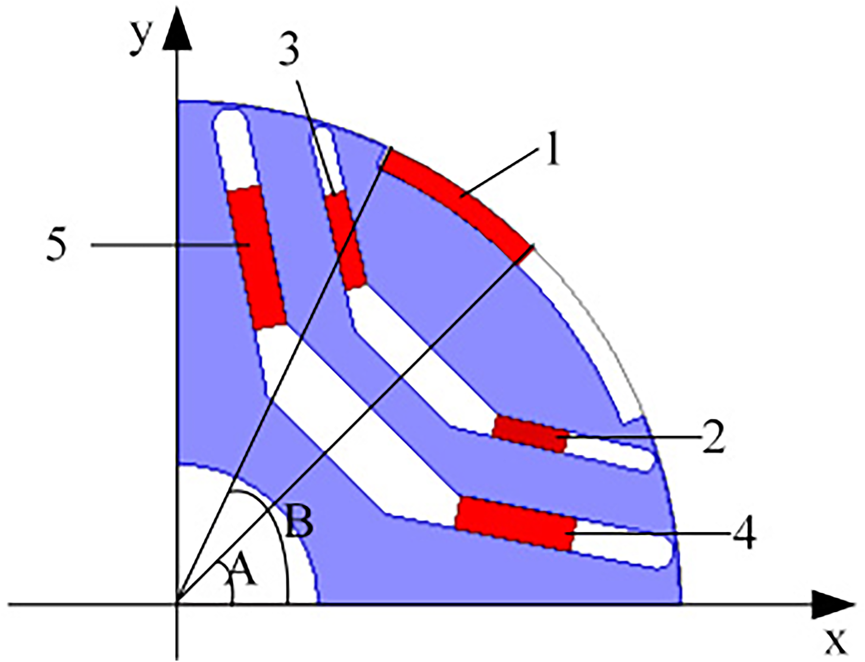
Permanent magnet schematic.
Factor level.
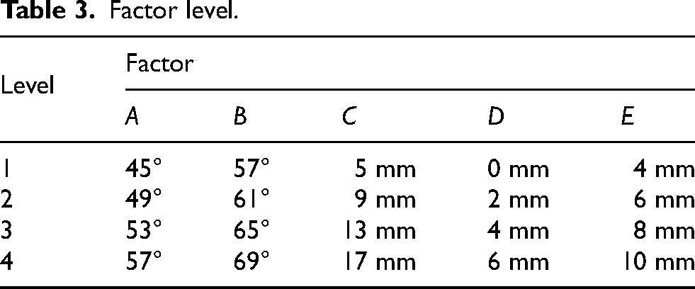
The orthogonal experiment table is a set of rules for designing tables, and the knowledge of Combination Mathematics and Probability is needed for constructing an orthogonal table. Generally, L is used as the code name of the orthogonal experiment table, n is the number of experiments, J is the number of levels, s is the number of factors, then this orthogonal table is represented by the symbol L n (J s ). Among them, the number of rows in the orthogonal experiment table represents the number of orthogonal experiments, and the number of columns represents the number of factors. The number of optimization variables determines the number of factors in the orthogonal experiment table. The values of the levels depend on the upper and lower limits of the optimization variables, and they are evenly selected in the variation range. The number of levels taken by each factor is related to the number of factors, and is needed to make the orthogonal experiment table satisfy the following characteristics:
(1) In each column of the orthogonal experiment table, each level appears an equal number of times;
(2) In any two columns of the orthogonal experiment table, the combination of each level appears and appears an equal number of times.
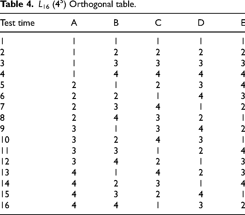
The above two points fully reflect the two major advantages of orthogonal experiment tables, that is, uniform dispersion and neat comparability. Each level of each factor touches each level of another factor once, so orthogonal tables must satisfy the above two points. The corresponding orthogonal table L16(45) is established according to the factor level table, as shown in Table 4.
L16 (45) Orthogonal table.
The mean value T and torque ripple T r corresponding to 16 orthogonal experiments are calculated by utilizing finite element software. The specific calculation results are shown in Table 5.
Test results.

Test results.
In order to analyze the influence and relative importance of each optimization variable on the average torque T and torque ripple T r , it is necessary to conduct average value analysis and variance analysis based on the results of 16 orthogonal experiments.
Overall mean analysis
Firstly, the overall average value m of each column in Table 5 is obtained, and its calculation formula is as follows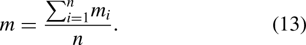
Using Eq. (13), it can be obtained that the overall average value m T of the average torque is 67.55, and the overall average value m Tr of torque ripple is 20.46.
Taking the average value of torque T under level 1 of factor A as an example, the specific calculation process is as follows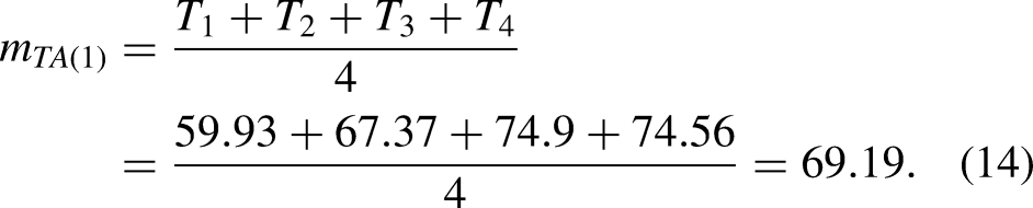
Similarly, the average value of average torque and torque ripple under each level of each factor can be obtained. The specific calculation results are shown in Table 6.
Average of factors at different levels.
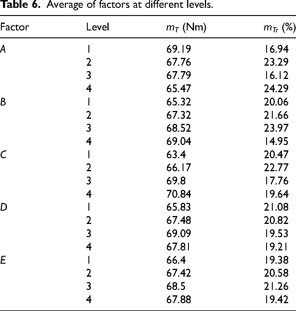
It can be seen from Table 6 that the combination of level taken by each factor to make the average torque maximum is A(1)B(4)C(4)D(3)E(3). Correspondingly, the combination of level taken by each factor to make the torque ripple minimum is A(3)B(4)C(3)D(4)E(1). However, the combinations of level taken by each factor that make the average torque maximum and the torque ripple minimum are different. Therefore, it is necessary to comprehensively consider the relative importance of each optimization variable on the average torque and torque ripple. Hence, it is needed to conduct variance analysis for the orthogonal experimental results, in order to obtain the optimal combination of level taken by each factor taking into account the average torque and torque ripple.
In order to obtain the relative importance of each optimization variable on the average torque and torque ripple, it is necessary to conduct variance analysis for the experimental results. The variance solution process of the average torque and torque ripple under each factor is as follows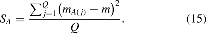
Taking the variance of average torque T under factor A as an example, the calculation process of this variance S
TA
is as follows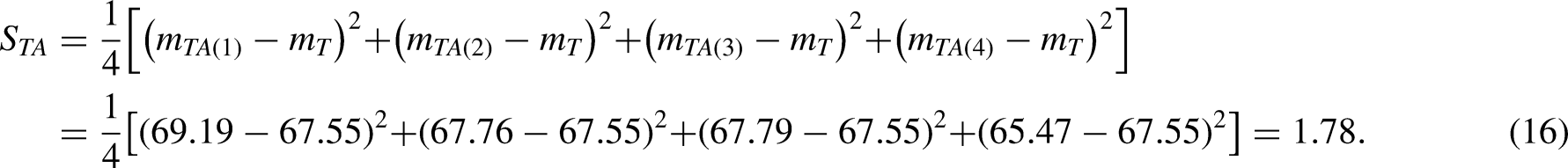
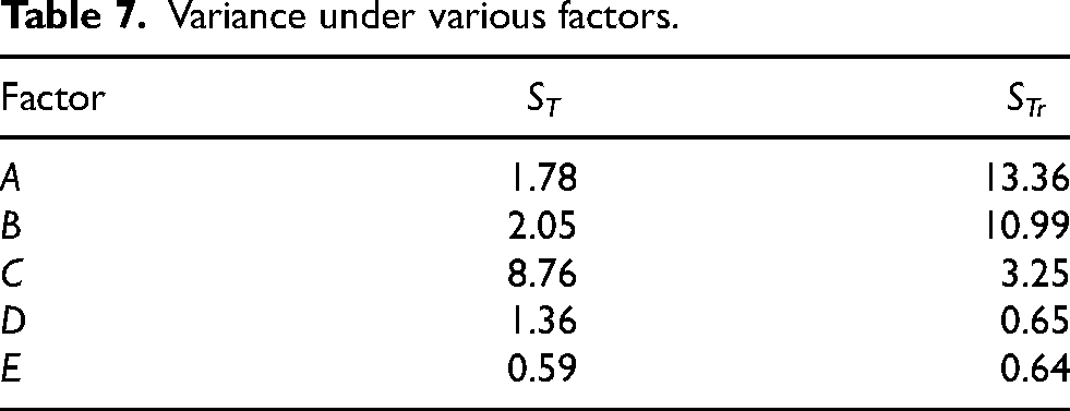
Similarly, according to Eq. (15), the variance of average torque and torque ripple under various factors can be obtained. The specific calculation results are shown in Table 7.
Variance under various factors.
In order to more intuitively obtain the relative importance of each optimization variable to the average torque and torque ripple, the variance proportion of each factor is specified. Aiming at the average torque, the variance proportion of each factor is calculated as follows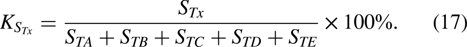
Aiming at average torque and torque ripple, the specific results of variance ratio under various factors are shown in Table 8.
Variance ratio under various factors.
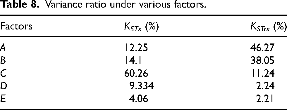
It can be seen from Table 8 that factor C has the greatest influence on the average torque. Therefore, factor C selects the level to make average torque maximum, namely C(4). Factors A and B have great influence on torque ripple, so factor A selects the level to make torque ripple smaller. Since the torque ripple under A(1) and A(3) are both smaller, A(1) or A(3) is selected. Factor B selects the level to make the torque ripple minimum, namely B (4). The importance of factor D and factor E to the average torque is more important than that to the torque ripple. Therefore, factor D and factor E choose the level to make the average torque maximum, namely D(3) and E(3). Finally, two combinations of the level taken by each optimization variable are determined, namely combination 1: A(1)B(4)C(4)D(3)E(3) and combination 2: A(3)B(4)C(4)D(3)E(3). Through the finite element simulation for the two combinations, it is found that the average torque and torque ripple of combination 1 are better than those of combination 2. Therefore, combination 1 is selected as the final optimized structure, and the corresponding rotor structure is shown in Figure 8.
Optimized motor structure.
The maximum value of total torque and the utilization rate of each torque component can be obtained by decomposing the torque of the optimized structure. The specific comparison of the torque waveforms corresponding to the improved structure and the optimized structure are shown in Figure 9. The torque waveforms of the improved structure are T2, Tpm2 and Tre2, and the torque waveforms of the optimized structure are T3, Tpm3 and Tre3. The overall comparison of the specific data corresponding to the traditional structure, the improved structure and the optimized structure are shown in Table 9.
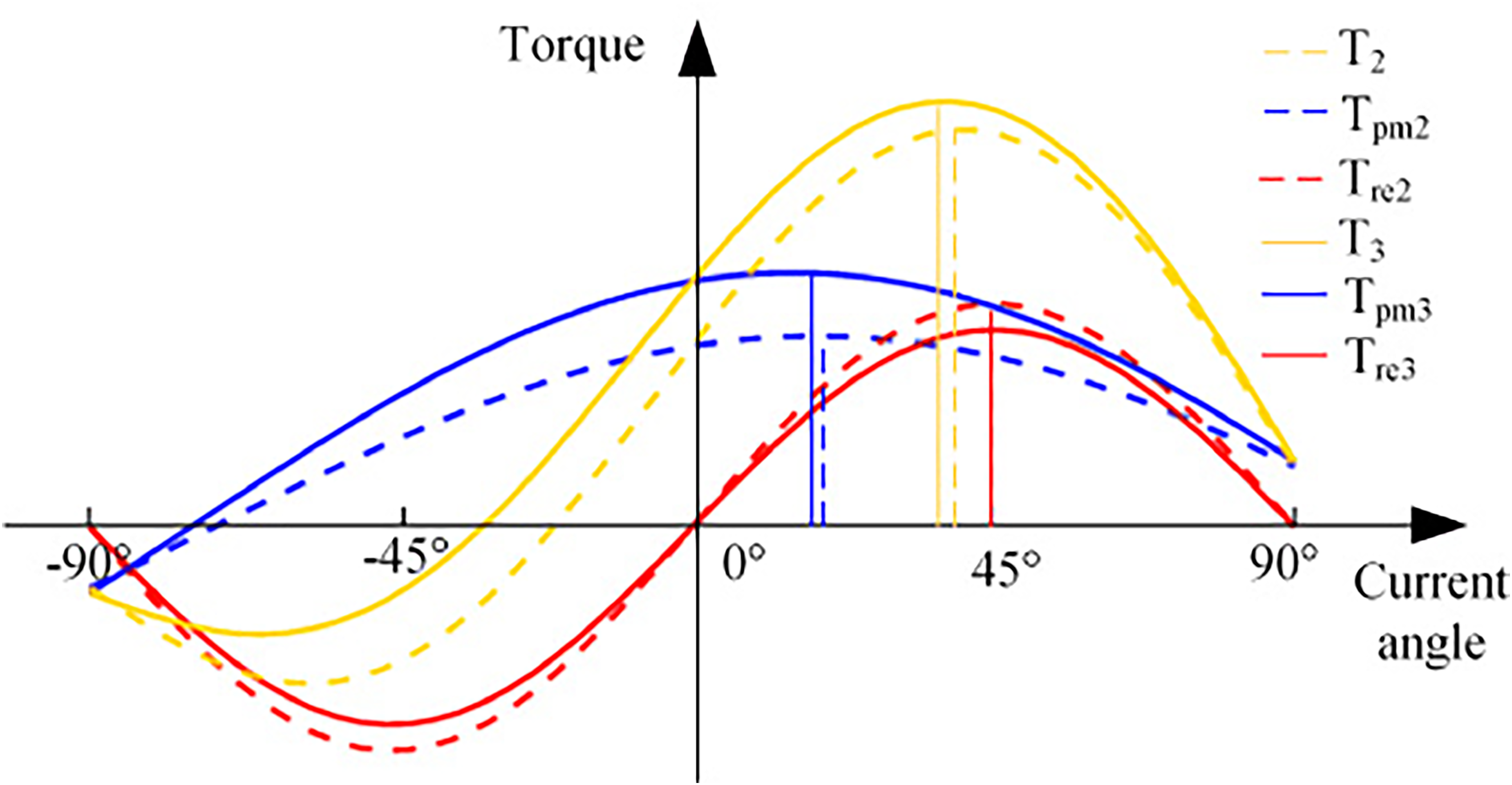
Torque waveforms comparison.
Specific data comparison.

It can be seen from Figure 9 and Table 9 that although the utilization rate of permanent magnet torque in the optimized structure is slightly lower than that in the improved structure, the maximum value of permanent magnet torque increases by 33%. Although the maximum value of reluctance torque in the optimized structure reduces by 11.6% compared with that in the improved structure, the utilization rate of reluctance torque is further improved. Hence, the maximum value of total torque in the optimized structure increases by 6.9% compared with that in the improved structure. In addition, the maximum value of total torque in the optimized structure increases by 18% compared with that in the traditional structure. Meanwhile, the torque ripple reduces by 41.45%, which demonstrates the effectiveness of the optimized structure. Meanwhile, the volume of the optimized structure of permanent magnets is smaller than that of the traditional structure of permanent magnets. The iron loss of the improved structure increases by 9% compared with the traditional structure. After optimizing the key parameters of the improved structure by the Taguchi method, the iron loss of the motor is reduced from 382.14W of the improved structure to 351.38W of the optimized structure, which is close to the iron loss of the traditional structure. This proves that the proposed optimized structure does not deteriorate the iron loss of the motor.
The new rotor structure and permanent magnet layout proposed in this paper effectively improve the power density by increasing the maximum value of permanent magnet torque and the utilization ratio of total torque to each torque component. Further, the matching design of key parameters in the improved structure is conducted by Taguchi method. The influence of each optimization variable on the average torque and torque ripple are analyzed. The optimal level value of each optimization variable is obtained, and the optimized structure is determined. Compared with the traditional structure, the maximum value of total torque in the optimized improved structure increases by 18%, and the torque ripple decreases by 41.45%. It shows that the proposed new rotor structure not only effectively improves the torque density, but also effectively reduces the torque ripple, which proves the effectiveness of the proposed rotor structure.
Footnotes
Acknowledgements
This work was supported in part by the project supported by National Natural Science Foundation of China under Grant 52077155, and in part by the project supported by the National Natural Science Foundation of China under Grant 52007132.