
Abstract
The suspension system integrating both vibration control and energy harvesting capabilities is denoted as Dual-function Suspension (DFS). The principal objectives for DFS encompass lightweight structure, high output force, extensive adjustability in damping, and minimized energy consumption. In pursuit of optimizing the linear motor and magnetorheological damper (MRD) amalgamated into the DFS, a multi-objective Particle Swarm Optimization (PSO) algorithm is conceived, emphasizing primary and secondary objectives to enhance the holistic performance of the DFS. A comprehensive mathematical model of the DFS is established, and subsequent to this modeling, the structural parameters of DFS are meticulously analyzed. Drawing upon the insights from this analysis, primary and supplementary optimization objectives are delineated, employing PSO for the refinement of the DFS structure. Following this, the Pareto solution set, derived from the optimization process, is judiciously selected utilizing fuzzy theorem principles. The outcomes reveal that, under the constraints of unaltered suspension packaging dimensions and overall energy consumption, the optimized suspension system manifests a 50% augmentation in output force, a 30% expansion in adjustable damping range, and a 39% reduction in thrust ripple compared to its pre-optimized state.
Keywords
Introduction
Suspension is an important factor in the performance of a vehicle. Traditional passive suspensions are difficult to adapt to changing road conditions due to non-adjustable stiffness damping [1]. The market share of active suspensions is gradually increasing as demand rises, but active suspensions dramatically increase energy consumption, maintenance costs, and package size to passive suspensions [2]. To overcome the problem of energy consumption, the feed-potential of the vehicle in bounce, pitch and roll modes is analyzed, assuming the damper is replaced by a lossless energy harvester that converts the kinetic energy generated by the vibration into useful energy source, such as electricity stored in batteries [3]. The result shows the necessity of energy harvesting function of vehicle suspension systems. Abdelkareem [4] comprehensively review the energy consumption of active vehicle suspensions and the associated actuator feedthrough potential, and analyzed suspension mechanisms such as suspension and pinions, ball screws, hydraulic motors and linear motors, noting that linear motors structures are simple and reliably integrated into existing vibration systems without transmission mechanism and are more suitable for vehicle vibration control than other structures.
When contrasted with a singular actuator, a hybrid actuator amalgamates various actuators in diverse configurations to enhance vehicular performance. Such hybrid systems bolster reliability, retaining functionality as passive suspensions in instances where the linear motor or the power supply system might falter. Unlike the linear motor, which often delivers diminished damping during energy regeneration, the hybrid actuator strikes a balance, diminishing total energy consumption while preserving the dynamic efficacy of the system [5]. In his study, Cai [6] delves into the intricate designs and applications of DFS, elucidating contemporary challenges and prospective avenues in the domain of vibration control research. Based on the hybrid actuators, Ding [7] has developed a mode decision and switching control to improve the vehicle’s overall performance, taking into account energy consumption and suspension performance. Wang [8] analyzed and verified suspension energy regeneration and suspension performance by paralleling a linear motor with three-stage adjustable damping as a DFS. The results show that energy regeneration is favored at lower fixed damping. However, the DFS is generally larger than a single actuator, which is not conducive to integration and needs to be optimized to achieve lightweight.
Optimization within the realm of vehicle suspension can be taxonomically segmented based on objectives, encompassing controller refinement, holistic vehicular performance enhancement, and actuator structural optimization. Addressing the inherent tension between divergent performance metrics within suspension systems, Li [9] introduced a dimensionless hybrid index rooted in safety probability as a metric to gauge suspension performance. This approach elegantly melds both ride comfort probability and handling stability probability, offering a unified dimension. In a quest to bolster both efficiency and capacity utilization, Sun [10] embarked on an exploration into the performance metrics of vehicular active suspension. This study was anchored on a seven degrees-of-freedom comprehensive vehicle model, augmented with a linear quadratic Gaussian active suspension controller. There exists a perennial tug-of-war between comfort and safety within the context of vehicle suspension efficacy, irrespective of it being a passive or active system. Taking this into consideration, Fossati [11] charted out a methodological framework geared towards the multi-objective optimization of a full-car model’s passive suspension system, particularly as it navigates erratic road profiles. Yildiz [12] considered with a non-linear suspension design for half vehicle model by using particle swarm optimization technique. The actuator’s performance is an important guarantee for the effective implementation of vehicle control. To obtain a better actuator structure, some scholars [13,14] have researched actuator structure optimization. Faramarzi [15] describes the design methodologies and optimization techniques studied in the performance improvement of line-start permanent magnet synchronous motors. And this study points out that steady-state performance and transient performance are a pair of conflicting optimization performance metrics. To solve the conflicts between the limitation of dimension [16] and the improvement of damping performance, Hu [17] proposed a new MDR structure and used an optimization method combining BP neural network and PSO to optimize the structure.
The optimization of vehicle suspension structure needs to consider a variety of conflicting performance indicators. For the multi-objective optimization of suspension performance and the selection of the optimization solution set, some scholars [18,19] have used different intelligent algorithms for the optimization of a single suspension. However, the DFS has multiple pairs of conflicting performance metrics, and how to deal with these conflicting metrics becomes an important problem in optimizing DFS. The particle swarm algorithm has a better robust performance for multi-objective optimization [20], which provides a better idea to solve this problem. Faced with the increase in the number of optimization objectives, Papaioannou [21] proposes a method for minimizing the number of objective functions for vehicle suspension optimization by dividing the objective function into main and supplementary targets for optimization as well as Pareto frontier solution set selection.
The DFS emerges as the premier solution in addressing the energy efficiency concerns of active suspension systems. To navigate the intricate balance between the DFS suspension’s overpack dimensions and its energy efficiency, this study crafts a meticulous mathematical model of the DFS. Leveraging this model, a sensitivity analysis was executed, focusing on pivotal structural parameters, encompassing aspects like the linear motor’s pole-arc coefficient, airgap thickness, permanent magnet length, slot width, MDR cylinder thickness, damping gap, and core radius. While the primary objectives targeted the maximization of output force and the minimization of pulsating force, secondary goals honed in on the damping adjustability range and minimizing the suspension overpack dimensions. The Particle Swarm Optimization (PSO) algorithm was employed for this optimization process. Subsequently, the Pareto solution was discerned through the principles of fuzzy set theory, with the resultant optimization outcomes being both resolved and corroborated using the finite element method.
Mathematical model and verification of the DFS
Structure and working principle
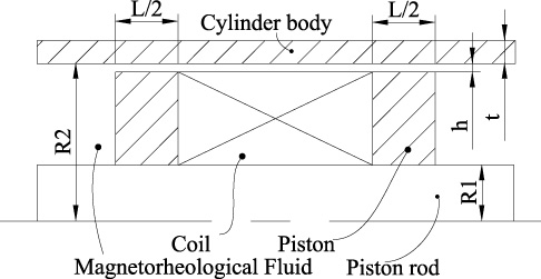
To reduce the outer packaging size of the suspension and improve the suspension performance, a parallel-type DFS was designed. The structure diagram is shown in Fig. 1, the DFS is a linear motor and MDR in parallel. The MDR provide continuously adjustable damping forces during suspension vibrations. The linear motor has two working states: generator state and motor state. When it is a generator, the suspension achieves energy regeneration, and when it is a motor, the linear motor supplements the damping force, thus improving the suspension performance.
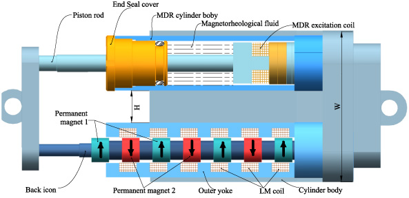
Structure of the DFS.
According to Fig. 1, to better ensure the suspension dynamics performance, the DFS should have the basic functions of large output force, large adjustable range, and better stability, and should also ensure that the suspension should meet the requirements of lightweight. To better establish the DFS mathematical model, it is necessary to establish an accurate model of a linear motor and MDR, where the linear motor measurement indexes include induced electric potential, and output electromagnetic force. The MDR force measurement index includes the maximum damping force and dynamic adjustable range. The performance parameters of the DFS are shown in Table 1, and the structural dimensions are shown in Table 2.
Performance parameters of the DFS
Where F l is the output electromagnetic force of linear motor, F um is the maximum output damping force of MDR, F lm is the minimum output damping force of MDR.
Key structure dimensions of the DFS
The DFS performance evaluation metrics include output force, electromagnetic thrust ripple, and dynamic adjustable range. To better analyze the influence of structural parameters on suspension performance, this paper sets the following rules for the DFS controller.
R1: Soft damping is beneficial to enhance the feeder potential, set F l ∕F m = u, the design of this value for control research related content, this paper selects u = 0.25.
R2:The distance between MRD and linear motor is constant to ensure that magnetic fields do not interfere with each other, this paper selects H = 10.
R3:The DFS-related structural parameters are divided into linear motor-related parameters and MDR-related parameters, and for better analysis of their performance, sensitivity analysis is performed for both of them separately, but it should be noted that they are divided into independent individuals here, which does not affect the subsequent optimization of the combined structure.
Electromotive force is an important performance parameter of the motor, and its sine degree and peak size are directly related to the effective thrust and thrust ripple of the actuator. In this study, the linear motor uses a slotted structure, and the slot opening will cause the airgap magnetic field flux leakage, which will affect the actuator-induced electric potential, so it is important to build a model of induced electric potential considering the slot opening. The partial structure of the linear motor is shown in Fig. 2.
Consider the effect of the notch and introduce the actuator coefficient K
c
.
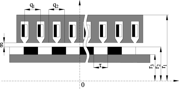
Structure of the linear motor.
The effective air gap of the actuator is shown in the Eq. (4).
At the equivalent armature radius, the single-phase winding magnetic chain can be obtained by taking the derivative of the magnetic flux density concerning the coil pitch.
The derivative of the magnetic chain concerning time yields the single-phase winding-induced electric potential E, as shown in Eq. (9).
To validate the formulated model, the finite element method was employed, and a two-dimensional model of the linear motor was constructed using ANSYS. The winding coil comprises a 1 mm diameter copper wire. The primary and secondary cores of the actuator are fabricated from 50WW800 silicon steel sheets, while the secondary permanent magnet is crafted from N35 material, characterized by a flux density of 1.2 T and a coercivity of 840 KA/m. The imposed boundary conditions adhere to the Dirichlet parallel constraints. Given the interdependence between the magnetic chain and winding relative to their initial positioning, the actuator’s starting position is designated at 0.018 m from the origin. This facilitates a comparative analysis of computational outcomes between the finite element and analytical solutions. The actuator’s traversal is aligned with a pair of poles. Figure 3(a) depicts the magnetic chain curve for the single-phase winding at an actuator velocity of v = 0.23 m∕s. Concurrently, the induced electromotive force curve across a pair of pole pitches for the actuator is illustrated in Fig. 3(b).
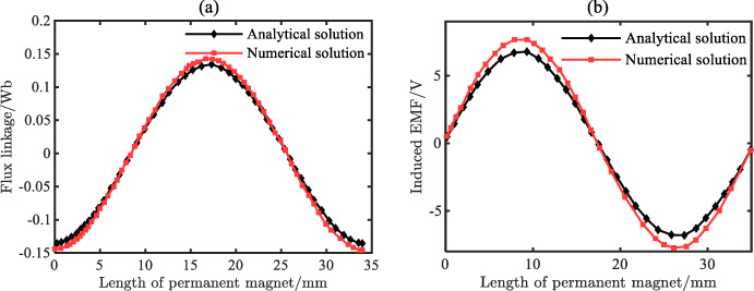
Simulation comparison of flux linkage and induced electromotive force.
From Fig. 3, the mathematical model of the induction potential of linear motor is consistent with the trend of simulation analysis. The peak error between the analytical and finite element solutions of the induced electric potential is 0.86 V in a pair of pole pitch ranges and is sinusoidally distributed. The output force of the linear motor can be adjusted in real-time by the input current and speed, and the output electromagnetic force of the linear motor component of the DFS is shown in Eq. (10) when the current excitation is applied.
The electromagnetic force simulation results and numerical analysis results are shown in Fig. 4.
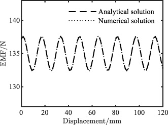
Electromagnetic force of the linear motor.
From Fig. 4, the numerical model solution results can better respond to the linear motor variation trend, and the maximum output force difference is 0.8 N, which may be due to the lower grid accuracy or lower harmonic order when solving. At the same time, it can be obtained that in the linear motor output electromagnetic force there is certain periodic thrust ripple, thrust ripple of about 10 N. The existence of such thrust ripple will reduce the reliability of the system.
The Bingham model is chosen as the MDR mechanics model, which is composed of the viscosity damping force and the field dependent damping force, as shown in Eq. (12). The partial structure of the MRD is shown in Fig. 5.
Structure of the MRD.
The magnetorheological fluid yield shear damping force can be expressed as follows.
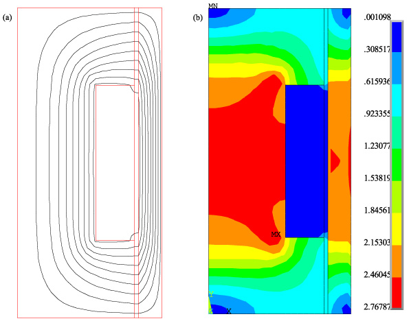
The electromagnetic field of the MRD was simulated by using ANSYS software, and the static characteristics of the magnetic field were analyzed. The winding coil is made of copper wire with a diameter of 1 mm, and magnetic material is steel 20#. The magnetic lines of force and magnetic field distribution are shown in Fig. 6(a) and Fig. 6(b), respectively. Meanwhile, to verify the reliability of the model, a vibration test platform was used to test the damping force with speed for different currents of the MDR, and the test platform and comparison results are shown in Fig. 6.
Finite element of MRD.

Test bench and results for MRD.
From the magnetic force lines and magnetic field distribution, it can be obtained that the MDR structure is reasonable, the magnetic induction strength in the effective damping channel is 0.7 T, and the magnetic force lines are perpendicular to the damping channel, which meets the design requirements. From Fig. 7, the results of the simulated solution fit better with the numerical solution, and there is some error in the simulated results compared to the experimental values when the applied currents are 0 A and 1 A, respectively. The error may be due to the existence of magnetic leakage and the deviation in the selection of the yield shear stress value of the magnetorheological fluid. Overall, the simulated and numerical solutions can reflect the MDR variation trend well and with high accuracy.
Structural parameters of linear motor
The evaluation index of linear motor components in DFS is the output electromagnetic force and electromagnetic thrust ripple. The linear motor in the ideal state can completely avoid electromagnetic thrust ripple, but it can be seen from the model that the linear motor winding induction potential contains a series of harmonic components, which under the action of the input three-phase current will cause electromagnetic thrust ripple. To facilitate the evaluation of the output electromagnetic force magnitude and the sine degree of the induced electromotive force, the amplitude of the induced electromotive force and the total harmonic distortion rate are used as evaluation criteria, respectively. THD is the sine degree of the induced electromotive force ripple, as shown in Eq. (15).
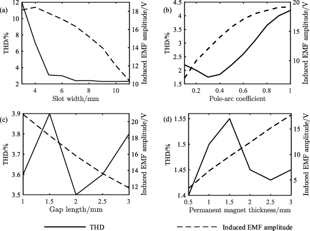
Combined with the analytical formula of induction potential, it can be seen that the factors affecting the harmonic content of induction potential are mainly the structural parameters of the motor. When the length of the motor, the number of poles, the number of slots, and the number of turns of the winding are certain, the main parameters are the pole-arc coefficient of the permanent magnet, the slot width, the permanent magnet thickness and the airgap. The effect of each parameter on the THD value and amplitude of the induced electric potential is analyzed, and the results are shown in Fig. 8.
As can be seen from Fig. 8, the value of THD decreases more rapidly with the increase of slot width, and when the slot width reaches 7 mm, the THD value remains stable. With the increase of pole-arc coefficient, the value of THD decreases first and then rises. With the increase of air gap length and permanent magnetic thickness, the value of THD varies less, which means that the value of THD has less influence on the induction potential thrust ripple. It can also be seen that the magnitude of the induced EMF amplitude tends to increase with the increase of the pole arc coefficient and the thickness of the permanent magnet, while the EMF tends to decrease with the increase of the air gap length and the slot width.
Influence of linear motor Parameters.
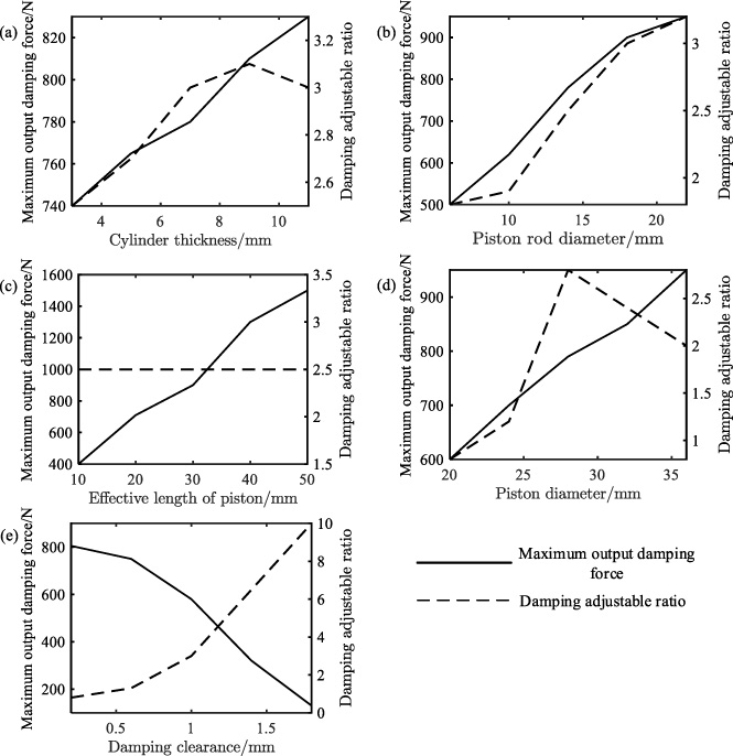
The output damping force and dynamic adjustable range are important indicators of the damping performance of MDR. Combined with the MDR dynamics model, it can be seen that the factors affecting the output damping force and dynamic adjustable range are mainly the structural parameters of the MDR. When the remaining parameters are fixed, the main parameters are damping gap, cylinder thickness, core radius, and effective damping length. The effect of each parameter on the output damping force and dynamic range is analyzed, and the results are shown in Fig. 9.
Influence of MRD Parameters.
As can be seen from Fig. 9, the output damping force increases with the decrease of cylinder aperture and damping gap, but the dynamic range decreases. When the piston diameter increases and the damping gap decreases, the output damping force increases and the dynamic range first increases and then decreases. The decrease of piston rod diameter leads to the increase of piston effective area, so the output damping force increases and the dynamic range decreases. The output damping force increases with the increase of damping effective length, but the dynamic adjustable range is independent of the piston effective length.
Linear motor electromagnetic thrust ripple, induced EMF amplitude, MDR output damping force, and the adjustable range will have a direct impact on the suspension system dynamics performance, and the optimization of the design can balance this impact. In this paper, a multi-objective particle swarm optimization algorithm based on Pareto dominance relations is used to optimize the structural parameters of the actuator from the perspective of DFS design. Considering the linear actuator optimization as a multi-objective nonlinear optimization problem with nth optimization objectives and u constraints, the multi-objective parameter optimization problem is described as follows.
Fluctuations in the output electromagnetic force can undermine the precision with which the actuator operates. Enhanced control is achieved with a more substantial maximum output damping force of the DFS and a broader adjustable range, culminating in superior suspension handling. In striving for an actuator that boasts a robust damping force output, minimal electromagnetic thrust ripple, expansive adjustability, and lightweight construction, it is crucial to strategically delineate objectives. This ensures that the optimization process is not beleaguered with superfluous solution sets stemming from a multiplicity of goals. Hence, in the schema of this optimization, substantial output force and minimal electromagnetic force oscillation are foregrounded as primary objectives. Concurrently, the adjustable range and the actuator’s weight are demarcated as secondary objectives. The main objective is articulated in Eq. (17), while the supplementary objective finds its expression in Eq. (18).
According to the parameter sensitivity analysis in Section 3, the linear motor airgap thickness, pole-arc coefficient, permanent magnet thickness, slot width, MDR cylinder thickness, piston rod radius, piston radius, damping gap, and effective length are selected as design variables, and the range of parameter values is determined according to the working requirements of a linear motor and MDR in the optimization process. The optimized design variables and constraints are shown in Table 3.
Design variables and constraints
The process of the particle swarm algorithm for finding the best can be rewritten in the form of a mathematical expression: assume that in the multidimensional space 𝛿
m
, n particles are randomly initialized as the initial particle population, then the initial position of the ith particle in the multidimensional space 𝛿
m
is vector
The complexity of particle swarm optimization can be represented by the formula:
Particle swarm optimization parameters
Take the average value after multiple runs, and the average calculation time of the particle swarm optimization algorithm is 3.1 seconds, The relevant hardware configuration is shown in the table.
Calculating hardware configuration
The program starts by determining parameters such as the learning factors C
1 and C
2, the maximum velocity v
max, the inertia weighting factor coefficient w, and the population size. In the global type optimization algorithm, a strong global search capability should be available at the early stage to locate the region where the best position is located, and a strong local search capability is required at the later stage to speed up the convergence of the optimization algorithm. To multi-objective particle swarm optimization algorithm work ideally, the inertia weight coefficients in the optimization algorithm should be made to adapt to the changes in the number of iterations by using a linearly decreasing iteration strategy as shown in Eq. (20).
The particle search speed will cause the algorithm optimization accuracy to decrease too much, and in the multi-objective particle swarm optimization algorithm, the maximum speed of the particles needs to be limited. Based on the search space of the particle population, the maximum velocity is defined as shown in Eq. (21).
For the DFS multi-objective particle swarm optimization algorithm model, the population size is selected as 50, and the parameter optimization results are obtained after 200 rounds of iterative operations, and Fig. 10 shows the Pareto optimal solution set.

Pareto optimal solution set.
From Fig. 10, The Pareto solution set consists of a series of non-dominated solutions, and the total harmonic distortion rate of the induction potential increases with the average output electromagnetic force. And the variation law of electromagnetic force is the same as the variation law of thrust ripple, so it is difficult to select the solution that best meets the requirement from the solution set. Because of subjective factors, when selecting the optimal Pareto solution, the decision maker often choose the one they think is the most optimal. To avoid the influence of such factors, fuzzy set theory is used to select the optimal Pareto solution set. Define the affiliation function as shown below.
According to Eq. (20), the dominance value of each non-inferior solution in the Pareto solution set can be calculated. The dominance value reflects the degree of superiority of the solution, and the larger the dominance value is, the better the quality of its solution is. According to this rule, the optimal solution of the solution set is selected by the dominance value. Figure 11 shows the dominance value of each non-inferior solution. The sixth particle in the Fig. 11 has the largest dominance value and is defined as the dominant solution. The design variables before and after the optimization of the DFS corresponding to this dominant solution are shown in Table 6.

Pareto optimal solution dominance function.
Design variables and constraints
According to the design variables in Table 6, the DFS finite element model of the optimized structure is established and the actuator performance before and after optimization is compared. The output electromagnetic force of the linear motor before and after the structure optimization under the three-phase AC excitation with the amplitude of 3 A in the linear motor part is shown in Fig. 12. Figure 13 shows the maximum output damping force under different current excitation before and after the DFS structure optimization. The main performance parameters before and after DFS optimization are shown in Table 7.

Linear motor output electromagnetic force before and after structure optimization.
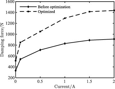
DFS structure output damping force at different currents.
In Fig. 12, the average value of the output electromagnetic force of the actuator is improved, the fluctuation of the output electromagnetic force is reduced, and the sine of the output electromagnetic thrust ripple is improved after structural optimization. The analysis shows that the DFS is optimized by the multi-objective PSO algorithm, which improves the average value of the output electromagnetic force and the amplitude of the induced EMF amplitude, and reduces the thrust ripple value of the electromagnetic force and the total harmonic distortion rate of the induced EMF. At the same time, it can be obtained that the optimized electromagnetic force is improved and the thrust ripple is reduced by about 10%, but comparing the optimized variables in Table 6, it can be seen that the outer diameter of the linear motor is expanded by 5%, which is in line with the actual and within the acceptable range. The reduction of electromagnetic thrust ripple can effectively improve suspension handling performance. At the same time, according to Table 7, the suspension outer package size did not change significantly.
Main performance parameters of DFS optimization
From Fig. 13, the MDR is optimized to increase the maximum damping force by 50%, and the adjustable range changes in a smaller range. Meanwhile, according to Table 7, the performance of the DFS suspension after combining the MDR and the linear motor is improved significantly compared with the performance of a single actuator, and the adjustable range increases by 35%, which is because the linear motor can provide the main power and reduce the minimum output damping force, which leads to a significant increase in the adjustable range. This also indirectly shows that the DFS structure has good fault tolerance and reliability.
In this paper, the analytical model of a linear motor and MDR is established for the problem that it is difficult to obtain the optimal solution because of the many factors affecting the DFS. On this basis, an active suspension mechanics model considering DFS is established, sensitivity analysis is performed on various factors affecting the suspension performance, and the structural parameters of the DFS are optimized with the help of multi-objective PSO intelligent optimization algorithm, which reduces the linear motor wave force while increasing the output damping force and improves the adjustable damping ratio of the actuator based on ensuring its lightweight. The design is verified by simulation, and the conclusions are as follows. The analytical solution model can simulate the experimental results well, and the errors between the analytical solution and the finite element solution cannot be avoided completely, but the results and trends of both are the same. The difference between the analytical and finite element solutions can be reduced when the high enough harmonic order is considered in the analytical model and the finite element software has properly meshed. The DFS gets a significant increase in output force for the same current excitation, which means that the overall energy consumption of the suspension is reduced for the same output force demand. The DFS structure is optimized by a multi-objective particle swarm, which can effectively improve the suspension performance. The maximum output damping force is increased by 50%, the adjustable range is increased by 30%, and the electromagnetic thrust ripple is decreased by 39%.
Limitations and Challenges in Research: PSO can, at times, get trapped in local optima instead of global ones, particularly in complex, high-dimensional search spaces. Typically, PSO uses the maximum iteration count as its stopping criterion, but this isn’t always the best choice, especially for computation-time-sensitive applications. In the practical utilization of DFS, there’s a higher requirement for control algorithm strategies, and the pronounced non-linearity of the magnetorheological damper presents a considerable challenge.
Footnotes
Acknowledgements
The research presented here was supported by the National Natural Science Foundation of China (51775426), Xi’an Science and Technology Development Program (21XJZZ0039), and Xianyang Key Research and Development Program (2021ZDYF-GY-0027). The authors are grateful for this support.