
Abstract
Spin-torque diode have shown great potentials and performance in many applicative fields, from microwave detectors to energy harvesters. In this work, we use micromagnetic simulations to study, at room temperature, a state-of-the-art non-resonant low-frequency-tail spin-torque diode in terms of dc output voltage as a function of the amplitude of an in-plane external field applied along different directions. We find that there exists a threshold value of the injected ac current that promotes a linear behavior of the output voltage of field down to the pT range, and we suggest exploiting such a behavior for the design of a magnetic field sensor.
Introduction
Spintronic diodes were born in 2005 [1] with the discovery that a spin-polarized microwave current can be converted into a rectified voltage in magnetic tunnel junctions (MTJs), thanks to a rectification phenomenon linked to the ferromagnetic resonance. The spin-torque diodes (STDs) are the dual effect of spin-torque oscillators [2–5]. They exhibit a number of advantages from their compatibility with the CMOS technology, which allows them to be integrated together in a chip [6], to be the smallest rectifiers developed so far (nanoscale size). STDs can operate in different regimes such as resonant, non-resonant, passive and active. For this reason, they can be used for many applications, ranging from microwave detectors to energy harvesters [7,8].
Initially, the STD effect was only exploited to measure the spin-transfer torque efficiency in MTJs [9–11], but later STDs have shown promising features for the integration in hybrid systems with better performances than the CMOS counterparts, i.e. Schottky diodes [12,13]. It has been experimentally proved that biased STDs can achieve a sensitivity (defined as the ratio between the rectified output and the input microwave power) larger than 10 kV/W, with output resistances smaller than 1 kOhm [13–17]. This is possible thanks to the excitation of strongly nonlinear dynamics, such as non-adiabatic stochastic resonance [14], out-of-plane precession [18], nonlinear resonance [15], resonant vortex expulsion [16], as well as injection locking [12]. However, for energy saving in Internet-of-Things nodes and electromagnetic energy harvesting, it is more convenient to design passive detectors that can work at ultralow power with a large signal-to-noise ratio [18,19]. The STD effect can be excited by Dzyaloshinskii-Moriya interaction [20] and spin-Hall effect [21,22], and used in probing domain wall’s dynamics in the free layer and the corresponding domain pattern [23]. It can also be employed in neurocomputing such a spin-torque nano oscillators hardware neural network [24] or sparse neuromorphic computing [25], in sensing, thanks to their very high sensitivity (up to 210 000 mVmW−1 [26]), as radiofrequency detectors [19,27–29], passive demodulation of digital signals and microwave imaging [30,31], as well as in antiferromagnets [32].
A promising application of STDs is the sensing of magnetic field due to the wide and common range of use of these sensors, such as in space [33], navigation and mechanical systems [34], automotive industry [35], industrial automation [36] and biomedicine [37]. The required characteristics of a magnetic sensor are sensitivity, field range, power consumption, costs and linearity [38,39]. In particular, linearity is crucial for a sensor output as it allows to determine the field intensity univocally, which leads to a simple circuitry, a better error propagation [39] as well as an easier optimization process compared to non-linear sensors [40].
The detection of magnetic field in the pT range is important for a wide range of industrial, homeland security, and biomedical applications [41,42]. For instance, neural activities are characterized by magnetic fields, induced by the electrical current spikes, on the order of pT and fT [43]. Similarly, the signal generated by proteins and DNA, as well as that of labels utilized to tag analyte and other cells/bacteria, is on the same order [42,44]. There have been proposals of pT magnetic field sensors based on MTJs [41,45–47], however these exploit the MTJs as magnetoresistive (MR) sensors and rely on arrays of MTJs and magnetic flux concentrators (MFCs) to enhance their detectivity and sensitivity.
In a non-resonant low-frequency STD working in the passive regime, i.e., when the magnetization is excited with an ac current with a frequency far from the ferromagnetic resonance (∼GHz), in the lower end of the spectrum, the amplitude of the generated dc voltage increases with decreasing the frequency of the input ac current. This makes non-resonant low-frequency STD appealing and promising solutions for low frequency applications. Hence, STDs can provide a higher sensitivity than traditional MR sensors, avoiding the need of arrays of MTJs and MFCs, with sub-micrometric device dimensions with respect to the millimeter to micrometer characteristic dimensions of the MR-based devices.
In this work, we propose to use a non-resonant low-frequency tail STD [48], where the interfacial perpendicular magnetic anisotropy (IPA) is compensated by the demagnetization energy, working in the passive regime as a magnetic field sensor with detectivity in the range of pT. Here we show, by means of micromagnetic simulations, that an in-plane magnetic field down to the pT range results in a linear change of the rectified output voltage generated by an input ac current at the MHz frequencies at room temperature. Our results pave the way for a novel application of this type of non-resonant STDs.
Device and model
In this section, we present the simulated device and the behavior of the rectified voltage when varying the in-plane x and y components of the applied field in the mT range. The simulated STD has an elliptical cross section of dimensions 130 nm × 46 nm, similar to previous studies on analogous systems where the IPA is balanced by the demagnetization contribution due the shape of the device [48–50]. The stack, from bottom to top is composed of PtMn(15) / Co70Fe30(2.3) / Ru(0.85) / Co40Fe40B20(2.4) / MgO(0.8) / Co20Fe60B20(1.65) (thickness in nm), where the bottom PtMn(15) / Co70Fe30(2.3) / Ru(0.85) / Co40Fe40B20(2.4) stack is the reference layer in which the PtMn layer is exchange biased to the synthetic antiferromagnetic structure Co70Fe30(2.3) / Ru(0.85) / Co40Fe40B20(2.4). Figure 1(a) shows a sketch of the MTJ structure.

(a) Schematics of the STD stack which consists of an in-plane magnetized reference layer and an in-plane magnetized free layer. (b) Time evolution of the dimensionless resistance (red curve) and normalized input current density (blue curve).
The micromagnetic model is based on the numerical solution of the Landau–Lifshitz–Gilbert equation with the Slonczewski terms [51,52]:
Effect of the in-plane magnetic field
Figure 1(b) shows the time evolution of the dimensionless resistance of the MTJ, calculated as r = 1 −〈m x 〉∕2 (with 〈m x 〉 being the normalized x component of the magnetization) and the normalized current density in the absence of an external field for a current density J = 2 MA/cm2. r describes the oscillations of the MTJ resistance R MTJ = R P + (R AP − R P )(1 − cos𝛽)∕2 and is defined to be centered in 1, with minimum value 1/2 corresponding to R P and maximum value 3/2 corresponding to R AP , for the sake of clarity in the plot. We can see that the current induces an in-plane precession of the magnetization with the same frequency as the injected current, but with a difference in its phase Δ𝜙 ≃ −80 deg, as in Ref. [48].
Let us consider now the effect of applying an in-plane magnetic field to our system. Figure 2 shows the effect of the external in-plane magnetic field applied along the x direction (Fig. 2(a) and (c)), which is the easy-axis of the free layer, and the y direction (Fig. 2(b) and (c)), on the rectified voltage V
DC
and the phase difference Δ𝜙 between the applied current and the magnetization x component. V
DC
is calculated from:

Rectified voltage plotted against the applied field along (a) x and (b) y axes, and the phase difference between the magnetization x component and the current density as a function of the applied field along (c) x and (d) y axes.
In Fig. 2(a) we can see that, by applying the external magnetic field along the x direction, we achieve an almost monotonical behavior of the absolute value of V DC , showing an increase of its value for an increasing intensity of the negative x-field, and a decrease for positive x-field. However, there is a small change in the slope around 5 mT. On the other hand, in Fig. 2(b), we can see that the effect of the field applied along the y direction has an almost symmetric trend for an increasing intensity of the field, both for negative and positive directions, with a minimum at H = 0 mT.
The behavior of the V DC when the external field is applied along x and y is accompanied by a similar trend of the phase difference, as shown in panels (c) and (d), respectively, suggesting that the effect of the magnetic field is to induce a change of the phase of the x component of the magnetization with the respect to the ac current, without modifying the frequency of the induced magnetization precession.
After characterizing the response over the mT range, we focus on the pT range by applying a positive field along the free layer easy-axis. With the aim to use the non-resonant STD as a pT magnetic sensor, we are looking for a linear response of the rectified voltage on the applied field. Then, we perform simulations for fields in the range 8 to 20 pT. The dc voltage exhibits an overall linear behavior, as shown in Fig. 3(a). We ascribe the difference from the ideal linear behavior to the effect of the thermal fluctuations which introduce a random response of the resistance when the effect of the ac current is dominated by the thermal field.
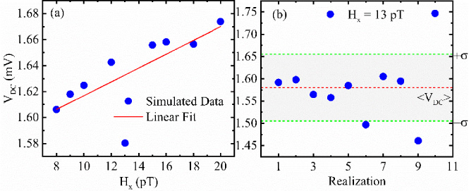
(a) Rectified voltage (blue dots) for fields applied along the x direction and the linear fit (red straight line) for J AC = 2.0 MA/cm2. (b) Output voltage for H x = 13 pT for various realization number. Red dashed line is the mean, while the green dashed one is the standard deviation. Highlighted gray area is where the data are inside the standard deviation.
To achieve a better understanding of the role of temperature, we performed additional simulations by fixing the in-plane external field to 13 pT for ten different realizations at room temperature (T = 300 K). The results are shown in Fig. 3(b), where the voltage outputs are scattered with the respect to the mean value of the voltage (red dashed line), resulting in a wide standard deviation (green dashed lines).
However, in order to obtain a linear magnetic field sensor in the pT range, it is enough to calibrate the input ac current. Indeed, by increasing the amplitude of the current density J AC from 2.0 MA/cm2 to 2.1 MA/cm2, the V DC behavior as a function of the field exhibits an excellent linear trend. This is shown in Fig. 4, where we plot the rescaled voltage ΔV DC = V DC − V DC (1 pT).
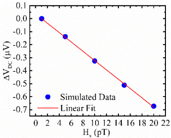
Rescaled rectified voltage (blue dots) for fields applied along the x-direction and linear fit (red straight line) of the data for J AC = 2.1 MA/cm2.
Moreover, if we measure the voltage difference between 5 pT and 1 pT, i.e. ΔV = V DC (5 pT) − V DC (1 pT) = 0.14 μV, we can see that the STD is sensitive to small changes of the external field. These results suggest that there exists a threshold current that allows to achieve a linear behavior and thus to utilize the STD as a magnetic field sensor at room temperature. This aspect is worth further investigation, and it will be object of a future work.
We have shown, by means of micromagnetic simulations, the effect of an in-plane magnetic field applied to a non-resonant low-frequency tail STD excited by an ac current at the MHz frequencies working at room temperature. The results show that it is possible to achieve a linear response of the output voltage generated by the STD as a function of the external field down to the pT range with a measurable output signal on the order of the μV. We find that there exist upper- and lower-bounds thresholds values for the input ac current for the system to yield a linear output. The lower threshold is dictated by the requirement for the external excitation to overcome thermal effects, whereas the weak amplitude of the fields determines the upper threshold. Our results prove how such a STD is a potential candidate for low-frequency magnetic field sensors down to the pT thanks to their sub-micrometric dimensions, robustness and low power. However, optimization of the device is necessary and will be object of further work.