
Abstract
Magnetic gears have attracted the attention of many scholars due to their advantages of low noise, maintenance free, high torque density and inherent overload protection. In this paper, three speed regulation methods of high power magnetic gear transmission system are summarized and proposed, and the finite element analysis of the three speed regulation methods is carried out by COMSOL Multiphysics simulation software. The results show that when the sizes of the three magnetic gears are similar, the output torque and load power of the speed regulation method of the magnetic gear using the magnetic field modulated type is the largest. On the contrary, the axial magnetic gear with air gap length regulation method has the lowest output torque and load capacity. Compared with the other two methods, the coupling length regulation method has the minimum eddy current loss and the simple speed regulation structure, which is the most suitable for high power magnetic gear.
Introduction
Magnetic gear (MG) is a kind of non-contact transmission mechanism. The magnetic drive technology and the basic model of the magnetic gear were designed based on the properties of permanent magnet materials that provide and maintain a stable magnetic field when magnetized, and the principle that magnetic fields can interact with each other. Magnetic gear is mainly used in the composition of composite motor. The combination of magnetic gear and engine ensures the compact structure and improves the efficiency of the motor [1]. At present, many mature products of magnetic gear and its composite motor have appeared in the market, and its application fields are expanding constantly. The characteristics of non-contact transmission of magnetic gear composite motor make it have development potential in medicine and food, new energy power generation, petrochemical industry and so on.
Field modulated magnetic gear is the most widely used magnetic gear at present. Field modulated magnetic gear works by transferring the magnetic field generated by a permanent magnet through a regulator [2]. The rotor in a magnetic gear consists of a different number of magnets attached to a yoke, and these rotors generate magnetic fields in opposite directions. In order for the torque generated by the rotors to be transmitted to the next stage, a magnetic field equivalent to the magnetic field generated by the rotors needs to be placed at the front of these rotors, which can be achieved by a soft magnetic assembly mounted between the inner and outer rotors [3]. Soft magnetic components are usually made of laminated steel or soft magnetic composite materials and are called regulators. The magnetic field generated by one rotor interacts with the magnetic field of the other side through the modulation of the regulator, so as to achieve the transfer of torque. The harmonic frequency of the magnetic field generated by permanent magnet in the air gap conforms to the sinusoidal law. The distribution of magnetic field in the air gap is related to the number of permanent magnets, the radius of the air gap, the thickness of the air gap, the magnetic properties of the permanent magnet synchronous motor, the number of opposite poles, the initial angle and the rotor speed [4]. Chau et al. [1] from Hong Kong University proposed a brushless motor based on magnetic field modulated magnetic gear. They transformed the inner rotor of magnetic gear into the outer rotor of permanent magnet brushless motor, realized effective integration of the brushless motor and magnetic field modulated magnetic gear, and significantly improved torque density and transmission efficiency of the mechanism [5].
Klaus Halbach discovered the Halbach magnetization method, which combines a radial arrangement of permanent magnets with a parallel arrangement. The Halbach arrangement can make the permanent magnet form a high intensity one-sided magnetic field, thus increasing the magnetoresistance and making the permanent magnet obtain higher torque density [6]. The simulation results also show that compared with the radial magnetization method, the Halbach magnetization method can improve the output torque, reduce the harmonic component in the internal and external air gap, reduce the floating frequency of the output torque, and improve the calculation accuracy of torque and loss [7]. Jian et al. [8] found that using high temperature superconducting materials to replace the ferromagnet in the magnetic modulator ring can weaken the influence of the end effect of the permanent magnet motor on the output torque and improve the structure of the magnetic gear. Rasmussen et al. [9] changed the magnetic circuit structure of the inner rotor to tangential type, improving transmission efficiency. Liu et al. [10] inserted the permanent magnet of the outer rotor into the soft-iron yoke of the outer rotor to increase the mechanical integration of the magnetic gear mechanism. Howe et al. [11] found that the degree of groove torque fluctuation is related to the number of rotors involved in magnetic coupling and the minimum common multiple of the modulating block of the modulating array. Niguchi et al. [12] studied the influence of magnetic flux density variation on torque transfer and found that the use of layered ferrite core of insulation layer as a magnetic modulating array to adjust the magnetic field can greatly reduce the eddy current effect.
Most scholars mainly study the topology of magnetic gear, but they rarely study the speed regulation method of magnetic gear. The research on the speed control method of large magnetic gears is still blank. In this paper, the speed control method of large magnetic gears is studied. Based on the analysis of magnetic coupler speed regulation method, the speed regulation method of magnetic gear is proposed. Finite element analysis is used to verify the feasibility of the speed regulation method. According to the conclusion of finite element analysis, the most suitable speed regulation method for large magnetic gear is summarized, which points out the direction for the following research.
Speed regulation method
Before the advent of new transmission devices such as magnetic gears, magnetic coupler was the traditional devices used to regulate speed. The magnetic coupler is composed of two rotors, which can realize speed regulation by changing the coupling flux density between the conductor rotor and the permanent magnet. According to its structure, magnetic couplers can be divided into cylinder type and disk type [13]. Cylinder-type magnetic coupler adopts coupling length regulation, and disk-type magnetic coupler adopts air gap length regulation. Referring to the structure of magnetic coupler, magnetic gear also has two speed regulation methods, namely coupling length regulation and gap length regulation [14]. The special structure of magnetic gear with magnetic field modulation makes the magnetic gear have another speed regulation method.
Coupling length regulation method
The coupling length regulation method of magnetic gear is similar to the speed regulation principle of cylinder-type magnetic coupler. This method is generally applicable to coaxial magnetic gear. See [15], Fig. 1 shows the basic structure of the magnetic coupler, which is mainly composed of conductor layer, permanent magnet body layer and gas gap. The outer rotor consists of a permanent magnet and its outer yoke iron, and the inner rotor conductor layer and its inner yoke iron.
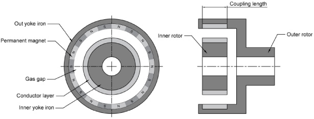
Cylindrical magnetic coupler. The basic structure of the magnetic coupler, which is mainly composed of conductor layer, permanent magnet body layer and gas gap. The outer rotor consists of a permanent magnet and its outer yoke iron, and the inner rotor conductor layer and its inner yoke iron.
Figure 2 shows the speed regulation principle of the cylindrical magnetic coupler [15]. By changing the meshing length of the inner and outer rotors, the coupling flux density between the conductor rotor and the permanent magnet remains unchanged, and the coupling flux area changes.
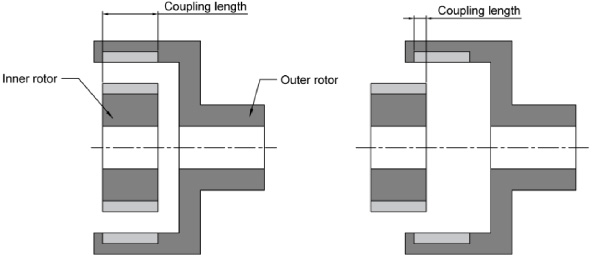
The speed regulation principle of the cylindrical magnetic coupler. By changing the meshing length of the inner and outer rotors, the coupling flux density between the conductor rotor and the permanent magnet remains unchanged, and the coupling flux area changes.
In the same principle, the magnetic gear adopts the method of coupling length speed regulation, the outer rotor can be connected to the drive shaft, and the automatic speed regulation mechanism can be set on the shaft to realize the axial displacement. The speed regulating mechanism and the outer rotor part of the magnetic gear are fixed by connecting parts and screws, and the coupling length of the outer rotor and the inner rotor is changed by adjusting the axial relative position between the inner and outer rotor, and the torque transmitted by the magnetic gear is controlled. According to the torque demand of load equipment, the coupling length between rotors can be adjusted to change the output torque and output power.
The air gap length regulation method of magnetic gear is similar to the speed regulation principle of disk magnetic coupler. This method is generally applicable to axial magnetic gear. Figure 3 shows the basic structure of the disk magnetic coupler, which consists of three parts: conductor layer, permanent magnet body layer and gas gap. The high-speed rotor consists of a conductor disk matrix and a conductor layer, while the low-speed rotor consists of a permanent magnet disk matrix and a permanent magnet body layer.
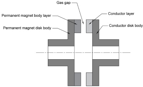
Disk magnetic coupler. The basic structure of the disk magnetic coupler, which consists of three parts: conductor layer, permanent magnet body layer and gas gap. The high-speed rotor consists of a conductor disk matrix and a conductor layer, while the low-speed rotor consists of a permanent magnet disk matrix and a permanent magnet body layer.
Figure 4 shows the speed regulation principle of disk-type magnetic coupler. When the speed regulating mechanism changes the air gap length of the high-speed rotor and the low-speed rotor, because the unit air gap flux density between the two rotors has changed, it will generate induced electromotive force and induced current, so that the output torque has changed, in order to achieve the speed regulating function.

The speed regulation principle of disk-type magnetic coupler. When the speed regulating mechanism changes the air gap length of the high-speed rotor and the low-speed rotor, because the unit air gap flux density between the two rotors has changed, it will generate induced electromotive force and induced current, so that the output torque has changed, in order to achieve the speed regulating function.
The magnetic gear adopts the method of air gap length speed regulation, the low-speed rotor and the high-speed rotor can be connected to two drive shafts respectively, and the automatic speed regulation mechanism is set on the shaft to realize the axial displacement. The speed regulating mechanism changes the length of the air gap by adjusting the axial relative position between the high-speed rotor and the low-speed rotor and the magnetic modulator ring, so as to control the transmission of torque of the magnetic gear. When the air gap length is small, the magnetic sensing lines passing through the two rotors are denser, the air gap flux density is larger, the torque generated is larger, and the working efficiency of the magnetic gear is higher. On the contrary, the magnetic sensing lines passing through the two rotors are sparse, and the air gap flux density and generated torque are small, which also leads to lower work efficiency [15].
High performance magnetic field modulated magnetic gear structure using Halbach magnetizing permanent magnet arrangement. Different from common magnetic couplers in structure, there is a layer of magnetic modulator ring structure between the outer rotor and the inner rotor. This layer of magnetic modulator ring structure can make full use of each permanent magnet in the inner and outer rotor, thus greatly improving the output torque and torque density of magnetic gear. Figure 5 shows the structure of high-performance magnetic field modulated magnetic gear [16].
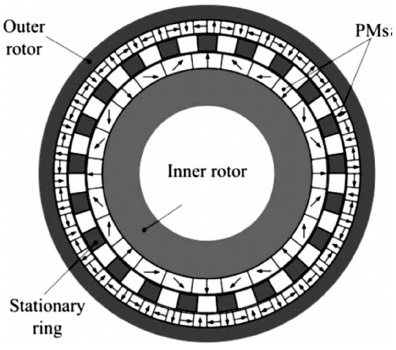
Field modulated magnetic gear. The structure of high-performance magnetic field modulated magnetic gear.
The three components of the field modulated magnetic gear can be selected to rotate any two of them, or the three components can be selected to rotate together. The third speed regulation method of the magnetic gear modulated by the field is to make the three components rotate together. When both the inner and outer rotors and the magnetic modulator ring rotate, the torque received by the inner rotors is equal to the input torque of the prime mover. In this working mode, when the prime mover drives the inner rotor of the magnetic gear to rotate, the torque on the magnetic modulator ring and the torque received by the outer rotor of the magnetic gear are only related to the input torque of the prime mover, and maintain a fixed and constant proportional relationship [16]. In other words, the electromagnetic torque between the inner rotor, the outer rotor and the magnetic modulator ring of the magnetic gear is decoupled. When the two parts of the magnetic gear are selected to rotate together, the other part is connected with the external device, and the three rotors all have an regulation effect on the output torque. This working mode is flexible and changeable, but also can improve the working efficiency of the magnetic gear.
Structure design and speed regulation by coupling length method
Structure design and model building
Coupling length regulation method is suitable for coaxial magnetic gear. As shown in Fig. 6, the inner rotor of the magnetic gear is composed of eight permanent magnets and a soft iron yoke, with two pairs of magnetic poles focusing on the rotor. The outer rotor consists of twenty permanent magnets and a soft iron yoke. Five pairs of magnetic poles focus on the rotor. The magnetic modulator ring consists of seven steel blocks with the same distance and remain stationary. This paper uses this typical structure to design and analyse the coupling length speed regulation method.

Coaxial magnetic gear. Coupling length regulation method is suitable for coaxial magnetic gear. The inner rotor of the magnetic gear is composed of eight permanent magnets and a soft iron yoke, with two pairs of magnetic poles focusing on the rotor.
In this simulation, the specific parameters of the magnetic gear are shown in Table 1. According to these parameters, we built its basic model in COMSOL Multiphysics, as shown in Fig. 7. The adjacent parts inside the inner rotor and outside the outer rotor are filled with Soft Iron Without Losses with relative dielectric constant of 1. Permanent Magnets with a conductivity of 10S/m were used to fill the inner and outer rotors. Air with a conductivity of 10 S/m is selected to fill the air part of the magnetic modulator ring, the consistent alignment part and the centre and outermost part of the magnetic gear. Linear magnet material (Steel AISI 4340) with a relative permeability of 8000 was used to fill the steel pole of the magnetic modulator ring. The magnetic poles of the magnetic gear are arranged according to the Halbach array, and the magnetic poles in the inner rotor, outer rotor and magnetic modulator ring are established into different entity domains. These are Inward Magnets, Outward Magnets, Clockwise Magnets, Anticlockwise Magnets and Steel. These are inward magnets, outward magnets, clockwise magnets, anticlockwise magnets and steel Poles). In this simulation, Ampere-loop law is adopted globally, and permeability is selected in the magnetization model of constitutive relation B-H. Inward magnet pairs, Outward magnet pairs, Clockwise magnet pairs and Anticlockwise magnet pairs, respectively the ampere-loop law was set for the adjacent parts in the inner rotor and outside the outer rotor, and residual flux density was selected for both magnetization models. Then add the force calculation of the inner rotor and the outer rotor, and the other parameters are generated by default. The free triangular mesh was used to divide the external rotor, the magnetic modulator ring and the inner rotor, and then the mesh was established in the form of sweeping. Finally, the set parameters and boundary conditions are studied, and the solver configuration is added through the steady-state solution and transient solution steps.
Specific parameters of the magnetic gear
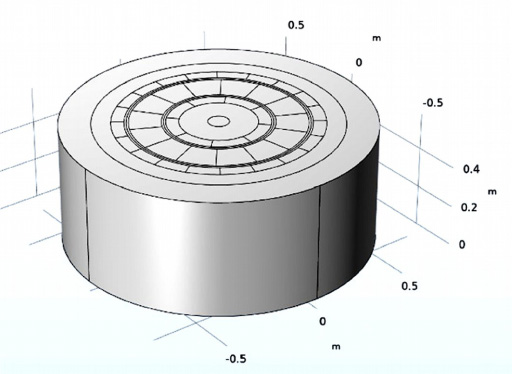
Basic model in COMSOL multiphysics.
The magnetic flux density mode image of the magnetic gear was plotted and the torque on the inner and outer rotors was calculated. The magnetic flux distribution on the surface of the gear was obtained, as shown in Fig. 8, and the variation of the torque on the inner and outer rotors was shown in Fig. 9. The maximum load power of the magnetic gear when it was fully coupled could be calculated through the torque diagram. The torque of the outer rotor is generally used as the output torque.
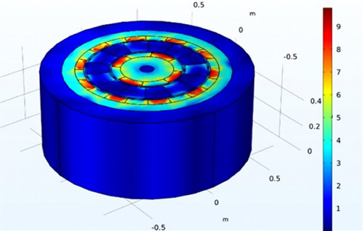
Magnetic flux distribution. The magnetic flux distribution on the surface of the gear.
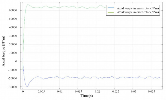
Torque on the inner and outer rotors. The variation of the torque on the inner and outer rotors was shown. The maximum load power of the magnetic gear when it was fully coupled could be calculated through the torque diagram. The torque of the outer rotor is generally used as the output torque.
Finite element simulation is based on the established physical model, adding material properties and meshing, then studying its steady-state and dynamic processes, and calculating and solving to obtain the results to be studied [17]. The coupling length between the outer rotor and the inner rotor is set as 100%, 75%, 50%, 25%, 0%, and the three-dimensional transient field finite element analysis is carried out respectively. The three-dimensional finite element models of coaxial magnetic gears with different coupling lengths are shown in Fig. 10(a–e).
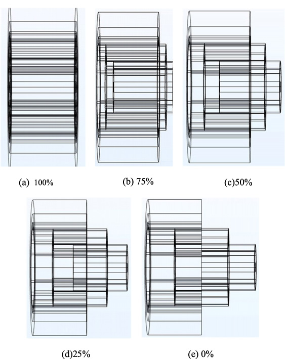
Coaxial magnetic gears with different coupling lengths. The coupling length between the outer rotor and the inner rotor is set as 100%, 75%, 50%, 25%, 0%, and the three-dimensional transient field finite element analysis is carried out respectively. The three-dimensional finite element models of coaxial magnetic gears with different coupling lengths are shown in Fig. 10(a–e).
Finite element analysis was carried out on the above five kinds of coaxial magnetic gears with different coupling lengths, and the output torques under different coupling lengths were obtained, as shown in Fig. 11. The load capacity are derived from the formula:
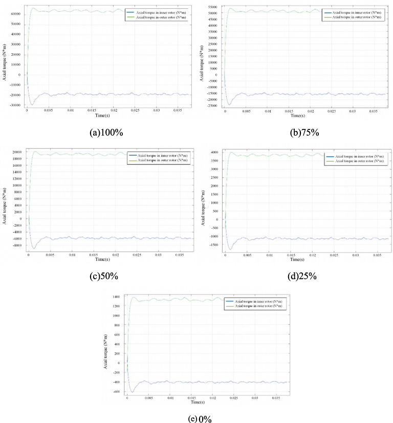
Output torques under different coupling lengths. Finite element analysis was carried out on the above five kinds of coaxial magnetic gears with different coupling lengths, and the output torques under different coupling lengths were obtained, as shown in Fig. 11(a–e).
Output torques under different coupling lengths
Structure design and model building
Axial magnetic gears include a low-speed rotor containing five pairs of magnetic poles, a high-speed rotor containing two pairs of magnetic poles, and a stationary rotor containing seven pairs of magnetic poles. In the field modulated axial flux magnetic gear, the rotors are arranged along the axis in the order of high-speed rotor, middle rotor and low speed rotor, and there is a certain air gap between them. According to the structural characteristics of axial magnetic gear, the magnetic field generated by the rotor has a larger interaction surface area, so the torque density of axial magnetic gear is higher than that of coaxial magnetic gear.
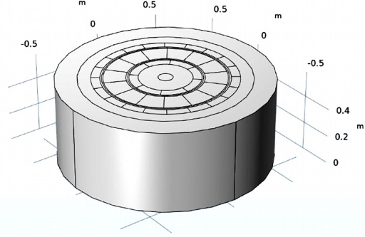
In this study, the three-dimensional model of field axial magnetic gear was first established by NX modelling software, then the model was imported by CAD import function in COMSOL software, and corresponding parameters were set similar to those of coaxial magnetic gear. The data are shown in Table 3, and the three-dimensional model of axial magnetic gear under COMSOL environment is obtained, as shown in Fig. 12. The gear material, pole arrangement, formula setting and mesh division are the same as those of coaxial magnetic gear. The magnetic flux distribution on the surface of the gear is shown in Fig. 13, and the axial torque changes of the high-speed rotor and the low-speed rotor are shown in Fig. 14. The axial torque of the low-speed rotor is used as the final output torque to obtain greater load power.
Specific parameters of the axial magnetic gear
Specific parameters of the axial magnetic gear

Model of axial magnetic gear. Three-dimensional model of axial magnetic gear under COMSOL environment.

Magnetic flux distribution on the surface of the axial magnetic gear.
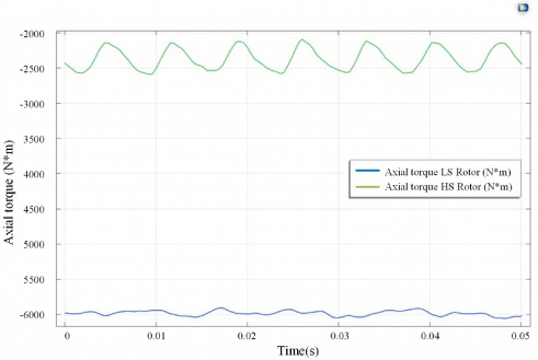
Axial torque of the high-speed rotor and the low-speed rotor.
Based on the above 3D model of axial magnetic gear with an air gap length of 0.03 m, the air gap lengths between the outer rotor and the inner rotor and the magnetic modulator ring were set as 0.03 m, 0.02 m, 0.01 m, 0.008 m and 0.006 m, respectively, and the three-dimensional transient field finite element analysis was carried out. Three-dimensional finite element models of axial magnetic gears with different air gap lengths are shown in Fig. 15.
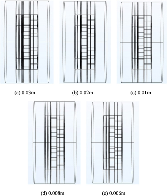
Axial magnetic gears with different air gap lengths. Three-dimensional finite element models of axial magnetic gears with different air gap lengths.
Finite element analysis was carried out on the above five axial magnetic gears with different air gap lengths respectively, and the output torque under different air gap lengths was obtained, as shown in Fig. 16. We can sort out the data and calculate the maximum bearing power, as shown in Table 4. The output torque of the axial magnetic gear model is 14000 N*m and the maximum power it can carry is about 1173 kW when the air gap length is 0.006 m.
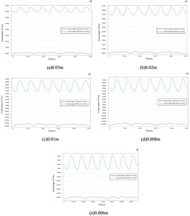
The output torque under different air gap lengths. Finite element analysis was carried out on the above five axial magnetic gears with different air gap lengths respectively, and the output torque under different air gap lengths.
Output torques under different air gap length
With the decrease of air gap length, the output torque of magnetic gear also increases. Both the magnetic field generated by permanent magnets and the induced magnetic field generated by the change of magnetic inductance line are variable. The reluctance in permanent magnets and air gaps is much larger than that in traditional cylindrical magnetic couplers, so more energy loss will occur in permanent magnets and gaps. This experimental result is also determined by its working principle. The increase of air gap thickness will lead to the increase of magnetic potential generated in the air gap, which will result in energy loss and thus lead to the decrease of output torque [2,18]. When the length of the air gap decreases, the air gap flux density between the inner and outer rotors increases, resulting in increased induced electromotive force and induced current, which makes the output torque increase, so as to achieve the control effect.
Structure design and model building
The permanent magnets of the new magnetic modulated gear adopt the Halbach magnetizing arrangement method in structure, and there is a layer of magnetic modulator ring structure between the outer rotor and the inner rotor. This layer of regulating ring structure can make full use of each permanent magnet in the inner and outer rotor, thus greatly improving the output torque and torque density of the magnetic gear. It is because of this structure that the magnetic field modulation type magnetic gear has a third method of speed regulation. The third method is to select the inner and outer rotor and magnetic modulator ring rotation mode. Table 5 shows the model parameters of the field modulated magnetic gear.
Parameters of the field modulated magnetic gear
Parameters of the field modulated magnetic gear
The magnetic gear model of the third speed regulation method is the same as that of the fully coupled state model established by the coupling length regulation method, as shown in Fig. 17. The gear material, pole arrangement, formula setting and mesh division are the same as those of coaxial magnetic gear. The inner rotor and the outer rotor rotate counter clockwise, and the magnetic modulator ring rotates clockwise. The rotation speed of the inner rotor and the outer rotor is unchanged, and the rotation speed of the magnetic modulator ring is defined to be the same as that of the outer rotor. Steady-state and transient solution studies were conducted on the set parameters and boundary conditions, and axial torques of the inner rotor, outer rotor and magnetic modulator ring were calculated, as shown in Fig. 18.
Model of the field modulated magnetic gear. The magnetic gear model of the third speed regulation method is the same as that of the fully coupled state model established by the coupling length regulation method.
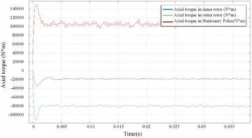
Axial torques of the inner rotor, outer rotor and magnetic modulator ring. The rotation speed of the inner rotor and the outer rotor is unchanged, and the rotation speed of the magnetic modulator ring is defined to be the same as that of the outer rotor. Steady-state and transient solution studies were conducted on the set parameters and boundary conditions, and axial torques of the inner rotor, outer rotor and magnetic modulator ring were calculated.
The axial torque of the inner rotor, outer rotor and magnetic modulator ring of the magnetic gear tends to be stable after a certain rotation time. The torque of input shaft was changed and four groups of control group were set. The output torque is shown in Fig. 19. Torque and load power are listed in Table 6. Then the ratio between the two of the three components is calculated. When the three components rotate at the same time, the output torque of the cylindrical magnetic gear model is 80000 N*m, and the maximum power that can be carried is 6684 kW. The only difference between this study and the coaxial magnetic gear is that the magnetic modulator ring also rotates, but the experimental results show that the output torque of the magnetic gear is greatly increased. With the decrease of input torque, the output torque of magnetic gear also decreases, and then the input torque is gradually reduced. Therefore, compared with the first two methods, this speed regulation mode has a variety of working modes. When the two parts of the magnetic gear are selected to rotate together, the other part is connected with the external device, and the three rotors all have a regulation effect on the output torque. This working mode is flexible and changeable, but also can improve the working efficiency of the magnetic gear.
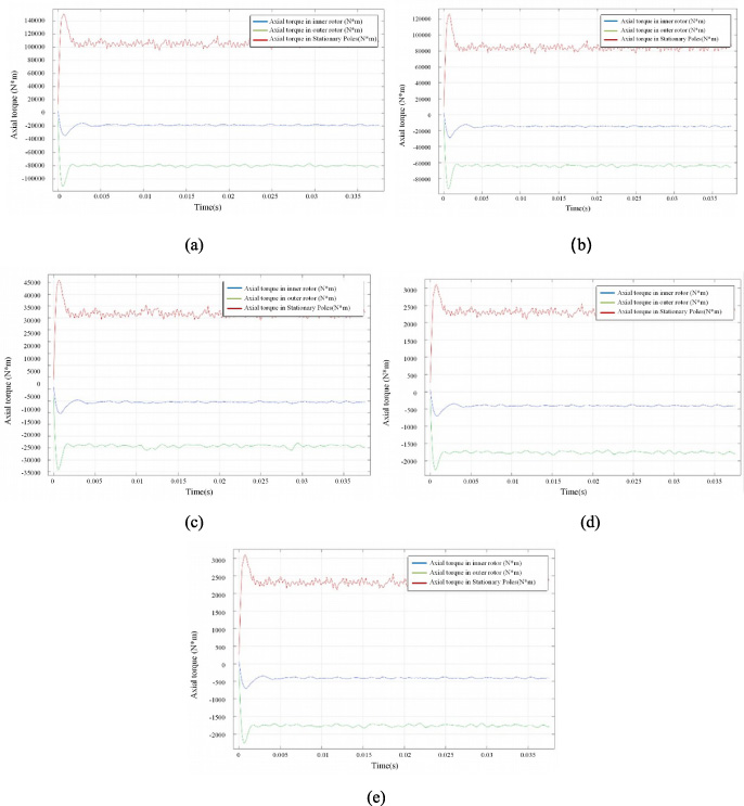
The output torque value for different input torques. The output torque is shown in Fig. 19(a–e). The axial torque of the inner rotor, outer rotor and magnetic modulator ring of the magnetic gear tends to be stable after a certain rotation time. The torque of input shaft was changed and four groups of control group were set.
Output torques under different input torques
The following results can be obtained from the experimental results of finite element analysis. Using coupling length regulation method, the output torque of cylindrical coaxial magnetic gear model with radius of about 0.5 m and height of about 0.5 m is 64000 N*m and the maximum power can be carried is about 5347 kW under 100% coupling length. Using the air gap length regulation method, the output torque of the cylindrical axial magnetic gear model with the same size is 14000 N*m when the air gap length is 0.006 m, and the maximum power it can carry is about 1173 kW. The magnetic gear has its own speed regulation method because of its structural characteristics. This method is suitable for magnetic field modulation type magnetic gear. According to the experimental results of finite element analysis, when the three components rotate at the same time, the output torque of the cylindrical magnetic gear model with this size increases to 80000 N*m, and the maximum power it can carry increases to 6684 kW.
From the above summary of the three speed regulation methods, it can be seen that, under the condition of keeping the same size of the three types of magnetic gears, the speed regulation method of magnetic gears with magnetic field modulation has greater output torque and carrying power, while the magnetic gears with air gap length regulation method have the minimum output torque and carrying power. After analysis, coupling length regulation method is most suitable for large magnetic transmission system, for the following reasons.
First, compared with coupling length regulating magnetic gear, air gap length regulating magnetic gear has some disadvantages: The permanent magnet material used in magnetic gear has strong magnetism, and axial force exists between high-speed rotor, low speed rotor and magnetic modulator ring, which will affect the stability of magnetic gear equipment. Therefore, additional mechanical structure should be added to strengthen it. When the high-speed rotor moves relative to the low-speed rotor, the variable magnetic field will be generated. Annular eddy current will be formed in the permanent magnet in the non-uniform magnetic field, resulting in energy loss, which will reduce the working efficiency of the magnetic gear. It is difficult to adjust the appropriate air gap. The smaller the working air gap between the rotor and the magnetic modulator ring, the larger the air gap flux density, which is conducive to improving the output torque and bearing power. However, too small working air gap will cause many problems in production, installation and use.
Second, compared with coupling length regulating magnetic gear, the speed regulation method of magnetic gear with magnetic field modulation also has some shortcomings: When using its own speed regulation method, the structure of the shaft is quite complex, and increases the additional power input, but also reduces the efficiency of the magnetic transmission system. We need to connect the magnetic modulator ring with the external input component as the speed regulating mechanism, and the inner rotor and the outer rotor as the input and output mechanism. This structure is equivalent to the mechanism with two inputs and one output. Adjusting magnet block in the middle of the two rotors, itself is not easy to install and fixed, but also to connect with the external parts of the rotation becomes more difficult, will also reduce stability. When the inherent speed regulation method is adopted, the eddy current loss will be twice, and the transfer efficiency will be reduced. From the energy loss and transfer efficiency of magnetic transmission system, the transmission efficiency of magnetic transmission system is related to slip rate. In common magnetic couplers, there is only a speed difference between the driving wheel and the slave wheel, which causes induced eddy current to be generated in the gear yoke, thus generating eddy current loss [19]. By adopting the speed regulation method of magnetic modulated magnetic gear, a layer of magnetic modulator ring is added to the structure. The inner rotor and outer rotor have speed difference with the middle rotor, resulting in greater eddy current loss.
Third, the coupling length speed control method, the bearing power can reach 5347kW, can achieve speed control range of about 0--98%, can meet the requirements of high power and high-performance magnetic drive system. In terms of structure, the external rotor can be connected to the drive shaft, and an automatic speed regulating mechanism can be set on the shaft to realize axial displacement. Therefore, the coupling length speed regulation method is more suitable for large magnetic drive system.
Conclusions
Combined with the research background and status quo of magnetic gear, this paper first introduces the structure and working principle of magnetic gear, and then further analyses the corresponding speed regulation method and principle according to the classification of magnetic gear, and obtains three speed regulation methods of magnetic gear, which are coupling length regulation method, air gap length regulation method and the speed regulation method of magnetic gear with magnetic field modulation. At the same time, the finite element analysis is used to verify the effectiveness of these three speed regulation methods. The basic comparison of these three methods of speed regulation, the analysis of the three methods is suitable for the scene, as well as its advantages and disadvantages. There is a certain gap in the research of speed regulation method of large magnetic transmission system, which has a certain practical significance for the development of new material transmission device.
The structure of permanent magnet magnetic gear is complicated. This paper mainly conducts finite element analysis on magnetic gear, focusing on electromagnetic field analysis. In order to improve the computational efficiency, other components with low correlation with magnetic field are ignored, so the experimental results obtained are too ideal. In order to better provide help for practical applications. In the process of simulation experiment, this paper only studies the speed regulation process of a group of magnetic gears. In order to make the experimental results more persuasive, it is necessary to carry out a number of groups of magnetic gear with different transmission ratios comparative experiment, so as to further study the speed regulation method of magnetic transmission system, for the future practical application to provide better guidance.
Footnotes
Acknowledgements
The authors would like to thank the School of Mechanical Engineering, Shanghai University for supporting this work.