
Abstract
A multi-mode wideband antenna based on multi-mode resonator is proposed with stable radiation patterns, which is composed of metal radiators, parasitic resonators, shorted patches fed by the U-shaped feedline, and a box-shaped reflector. A prototype of the proposed antenna is designed, fabricated, and tested. Measured results show that the antenna achieves an impedance bandwidth of 37.5% (0.67–0.98 GHz) for |S 11| < −15 dB, a half-power beam width (HPBW) of 67.5 ± 2.4 degree at H-plane (horizontal plane), and a gain of 8.0 ± 0.5 dBi. Furthermore, the cross-polarization discrimination (XPD) is more than 15 dB at 0 degrees and at least 11.2 dB within ±60 degrees at H-plane, respectively. The proposed antenna can be used in the modern communication systems for LTE700/GSM850/GSM900.
Introduction
With the development of modern wireless communication technology, broadband or multiband antennas are needed to be used in communication systems. Multi-mode wideband antennas are very helpful in countering multipath fading and increasing channel capacity [1–6]. Therefore, the multi-mode wideband antenna is proposed to introduce new modes with simple parasitic loading. The multi-mode theory is one of the methods to achieve broadband. Some antennas can only produce a single resonant mode, which makes it difficult to form broadband. Some antennas generate multiple resonant modes, but the frequency between the modes is large, which makes also it difficult to form a broadband. However, by controlling the movement of resonant modes, each resonant mode is moved to a close frequency point to form broadband [7,8].
In [7], wideband stub-loaded slot line antennas under multi-mode resonance operation were proposed. The second resonant mode is introduced through slot stubs. The length of slot stubs is changed to move the mode. In [8], three resonance modes are generated by introducing two pairs of slot stubs, resulting in a wide impedance bandwidth. The multi-dipole is proposed for stable radiation patterns [9]. In [10], a resonator-loaded broadband antenna is proposed, and the easily installed resonator is useful for effectively improving the impedance bandwidth. Inspired by this paper, this work is proposed. The multi-mode wideband antenna is a good method to realize the broadband requirements of wireless communication. Multi-mode technology can be used to obtain more resonant modes in the base station antenna, and can also be used in the terminal antenna with limited space to obtain wider bandwidth. To sum up, this is a kind of widely used and simple design method. In this paper, a multi-mode wideband antenna based on a multi-mode resonator for LTE700/GSM850/GSM900 is proposed. A parasitic rectangular resonator placed beside the radiator is employed to broaden the impedance bandwidth. The resonance modes can be controlled by adjusting the size of the parasitic resonator. This is a method to design a multi-mode wideband antenna and the proposed antenna with multi-mode wideband is a good choice for LTE700/GSM850 /GSM900 base stations.
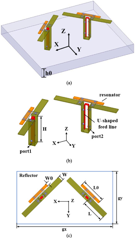
Geometry of the proposed design. (a) 3D view. (b) Antenna element. (c) Top view (H = 93 mm, h0 = 60 mm, L = 88 mm, L0 = 88 mm, W = 20 mm, W0 = 10 mm, gx = 340 mm, gy = 340 mm).
Antenna design
Figure 1 shows the geometry of the proposed antenna. The multi-mode wideband antenna is composed of two metal radiators, two parasitic resonators, two U-shaped feedlines, and a box-shaped reflector. Figure 1(a) shows an overall view of the proposed antenna. The angle between two antenna elements is placed at 90 degrees. The box-shaped reflector is introduced to increase the gain and improve the stability of the radiation patterns. Figure 1(b) shows the configuration of the antenna element. The metal radiator is fed by a U-shaped feedline, the arm of the metal radiator is in the same plane as the resonator, and they are fixed with a substrate. The resonant mode can be effectively moved by changing the length of the resonator. It is a method to design a multi-mode wideband antenna by controlling the frequency shift of resonant mode to form a broadband. The box-shaped reflector plays the role of enhancing gain and controlling beam width. The proposed antenna is simulated by HFSS.
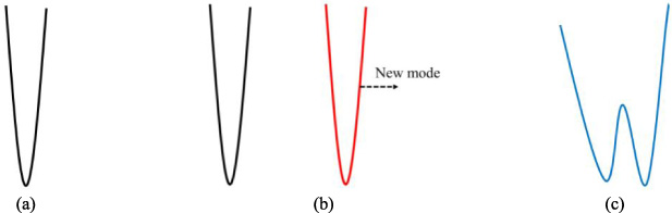
Basic mechanism of multimode wideband antenna. (a) Original resonant mode. (b) Two resonant modes. (c) Broadband resonant mode.
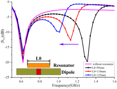
Effects of L0 on |S 11|.
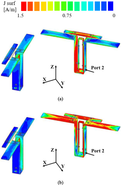
Current distribution of two modes by port 2. (a) 0.72 GHz. (b) 0.92 GHz.
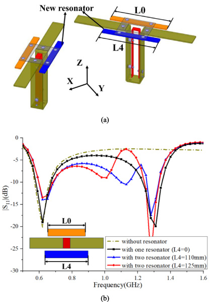
Effects of L4 on |S 11|. (a) Model. (b) |S 11|.
The principle of designing a multi-mode wideband antenna is to form multi-resonant modes and control the position of the resonant modes, finally achieving the purpose of broadband. If resonant modes are too far away from the frequency or only a single resonant mode, it will be very difficult to form a broadband. The resonator is used to generate coupling with the arm of the metal radiator, thus generating a new resonance mode. Figure 2 shows the basic mechanism of a multimode wideband antenna. Figure 2(a) shows that a conventional antenna has a resonant mode. The new resonant mode is introduced, as shown in Fig. 2(b), but the two resonant modes are too far apart to form broadband characteristics. Figure 2(c) shows that after the two resonant modes are close together, a broadband characteristic is formed compared to Fig. 2(a).
The method of generating multiple modes by loading a resonator to form a wideband antenna has been explained in Fig. 2. A new resonant mode can be produced by introducing a resonator, but controlling the position of the mode is another problem. We control the position of the new mode by adjusting the length of the resonator [10]. Figure 3 shows the effects of L0 on |S 11| simulated by HFSS. When L0 is equal to 0 (the resonator does not exist), the antenna generates one resonant mode at the operating frequency. This cannot meet our expectations of designing a wideband antenna. The resonator introduces a new mode. With the increase of L0, the new mode moves to the low frequency. The length L0 of the resonator is controlled to adjust the position of the second resonant mode independently, while the other resonant mode is not affected, so a wideband antenna is realized.
A new resonant mode is introduced by loading a resonator so that the antenna has two operating modes. In order to better understand the working mechanism of the two resonant modes, the current distribution diagram of the two resonant modes is shown in Fig. 4. When the antenna is working in the first resonant mode in Fig. 4(a), the lower end of the radiator (U-shaped) current is strong, and the resonator also has a small current distribution. The first resonant mode is mainly excited by the lower end of the radiator. When the antenna works in the second resonant mode in Fig. 4(b), the upper-end current of the radiator is strong, and the resonator also distributes a strong current. The second resonant mode is excited by the upper end of the radiator and the resonator. It also explains why the position of the second resonant mode can be controlled by changing the size of the resonator.
The previous part discussed the introduction of a single resonator. The second resonant mode can be adjusted independently. Therefore, we are interested in the influence of introducing more resonators on the antenna characteristics. Two resonators are introduced and placed on the different sides of the radiator arm as shown in Fig. 5(a). The new resonator is marked blue in the antenna model and the length is noted as L4. Figure 5(b) shows the effects of L4 on |S 11| simulated by HFSS. When no resonator is introduced, the antenna only generates one resonant mode at the operating frequency. When a resonator is introduced, a new resonant mode is introduced. When two resonators are introduced, two new resonant modes are introduced. The change of the length resonator L4 can adjust the second resonant mode independently, while not changing other modes. The introduction of multiple resonators can increase and adjust the resonant modes, which provides a method for the design of multimode wideband antennas.

Phototype of the proposed antenna.
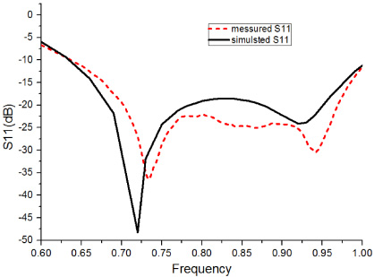
Measured and simulated |S 11| of the proposed antenna.
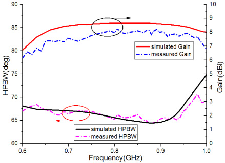
Measured and simulated HPBW and gain of the proposed antenna.
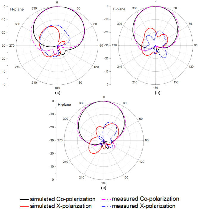
Radiation patterns of the proposed design at port 1. (a) 0.7 GHz. (b) 0.85 GHz. (c) 0.95 GHz.
The proposed antenna is fabricated to verify the proposed design. The phototype is shown in Fig. 6. The reflecting plate is composed of an aluminum plate, and the U-shaped feedline is connected to the coaxial cable. The proposed antenna was measured by two ports Agilent N5230A network analyzer and anechoic chamber. Figure 7 shows the measured and simulated |S 11| of the proposed antenna. The measured impedance bandwidth covers from 0.67–0.98 GHz (the relative bandwidth is 37.5%) for |S 11| < −15 dB. The measured and simulated HPBW and gain of the proposed antenna can be seen clearly in Fig. 8. The measured gain is 8.0 ± 0.5 dBi, and the simulation gain is 8.82 ± 0.82 dBi. Due to the inevitable loss of the coaxial cable, the measured result is slightly lower than the simulation result, but the curve trend is generally the same. The tested HPBW is 67.5 ± 3.5 degrees, which can be seen that the measured and simulated results are very consistent. The radiation patterns at H-plane are shown in Fig. 9 when port 1 is excited. The XPD within ±60 degrees is less than 11.2 dB, and a stable radiation pattern is achieved.
Table 1 shows the physical characteristics of the proposed antenna compared with some recent antennas. The impedance bandwidth of the proposed antenna is 0.67–0.98 GHz, and the relative bandwidth is 37.5%. Compared with other recent antennas, the bandwidth of our antenna is the widest. At the same time, the XPD within ±60 degrees is better than several recent antennas. The radiation pattern of the proposed antenna in the far field is very stable. Metal materials are used to form this antenna, which is a practical plan.
Physical characteristics of the proposed antenna compared with some recent antennas
Physical characteristics of the proposed antenna compared with some recent antennas
In addition, the idea of building a multi-array antenna is proposed. Figure 10 shows the design scheme for the multi-array antenna. The position of the star represents the position of the higher band element. Based on the principle of multi-mode antenna, it can be applied to a multi-array antenna to achieve wider bandwidth and higher gain.
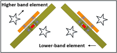
Design scheme for multi-array antenna.
A multi-mode wideband antenna with a stable radiation pattern and high XPD has been proposed. The proposed antenna consists of metal radiators, U-shaped feed lines, resonators, and a boxed-shaped reflector. An impedance bandwidth of 37.5% (0.67 to 0.98 GHz) for |S 11| < −15 dB has been achieved, and HPBW is 67.5 ± 2.4 degrees at the H-plane, while the radiation pattern is very stable. The example of loading two resonators also has been discussed through HFSS simulated results, and this antenna generated three resonant modes. The possibility of loading multiple resonators has been further verified, and a method of constructing multi-mode wideband antennas has been provided. The proposed antenna is a good choice for LTE700/GSM850/GSM900.
Footnotes
Acknowledgements
This work was supported in part by the National Nature Science Foundations of China under grant 61901176, in part by the Dean Project of Guangxi Wireless Broadband Communication and Signal Processing Key Laboratory under grant GXKL06220204, in part by the China Postdoctoral Science Foundation under Grant 2019T120730, and in part by the Research and Development Project in Key Field of Guangdong Province, China under grant 2022B0701180001.