
Abstract
It is necessary to detect subsurface defects for a key metallic structural component especially a multilayer coating to ensure its structural integrity. In this paper, an imaging algorithm using the synthetic aperture focusing technique (SAFT) is developed for processing surface wave signals of array pickup electromagnetic acoustic transducer (EMAT) to improve its signal-to-noise ratio and detectability of subsurface defects. In addition, an array pickup unit of surface wave EMAT with gap configuration is proposed to receive multi-channel surface wave signals and is optimized by adjusting its coil configuration such as number, spacing and detection distance in order to obtain better SAFT imaging result. Both simulation and measured EMAT surface wave signals are used for the defect imaging and all the results verified the validity and the efficiency of the proposed method.
Introduction
Defects nearby the surface of a metallic structural component are possibly propagating into the deep material or causing debonding of surface layer due to alternative mechanical or thermal load [1]. It is important to detect subsurface defects in a metallic structure nondestructively to ensure its structural integrity. Water immersion ultrasonic testing technology can be used to detect subsurface defects in structural component. The challenge is that the used bulk waves may cause overlap of the defect echo and the interface echo. Extracting the defect echo and quantifying it requires complex signal post-processing procedure. Moreover, the application of piezoelectric transducer and requirement of water coupling agent make it not suitable for in-service inspection and high-temperature environment [2]. Laser induced phased arrays UT is a couplant-free ultrasonic inspection technique using bulk waves that can image near-surface defects. However, the presence of multi-mode waves easily leads to crosstalk and artifacts [3]. Infrared thermal imaging technique has high accuracy in near-surface defect detection and imaging, but requires cleaning the surface of the specimen before inspection, as surface blots can be treated as defects, leading to missed detections [4,5]. The surface acoustic wave is sensitive to the subsurface defects as the wave energy is mainly concentrated in the near-surface zone [6,7]. The EMAT is a non-contact and efficient technique to generate surface wave for detecting subsurface defect in a metallic structure. It has low requirements for the surface of specimen and does not require coupling agents. While its low energy conversion efficiency and weak detection signal cannot be ignored [8]. It is necessary to develop a method to improve the performance of surface wave EMAT in order to detect small subsurface defects.
The SAFT can improve signal-to-noise ratio (SNR) of defect echo through superposition of defect echoes in signals at different detection positions, and has been successfully applied to bulk wave ultrasonic testing (UT) [9,10]. Kou et al. employed the SAFT to deal with the multiple signals obtained by the laser ultrasonic testing and enhanced the detectability and imaging accuracy of thick metallic component [11]. Lv et al. used the SAFT to visualize subsurface defects in additive manufactured structural components. The ultrasonic signals were acquired through laser-ultrasonic raster scans and the imaging results were well consistent with the actual values [12]. Qin et al. applied the SAFT to detect submillimeter flaws in strongly scattering metallic materials. The SNR were improved and the defects with size of 0.2 mm and 0.3 mm in a 304 stainless steel specimen were imaging properly [13]. As an efficient signal processing method based on multiple UT signals, SAFT can be applied to surface wave EMAT if multi-channel surface wave signals can be acquired. To enhance energy conversion efficiency, excitation unit of EMAT usually chooses large-sized meander or racetrack coils to generate surface wave of higher wave energy [14,15]. Because of the larger size and fewer channels of the excitation unit, the number of received signals is small and the improvement of SNR after SAFT superposition is not significant if the excitation coils are also used as pickup unit. A transmission and receiving (TR) type array pickup EMAT with multiple pickup coils has potential to collect better EMAT signals.
Under these backgrounds, this paper proposes an imaging algorithm using SAFT based on multiple surface wave signals of an array pickup EMAT to enhance its detectability of subsurface defects in metallic structures. The SAFT is updated for the surface wave signals excited by a linear racetrack coil excitation unit and received by an array pickup unit to improve the signal SNR and defect imaging results. Through optimizing the number of effective coils, coil spacing, and detection distance, an array pickup unit with gap configuration is designed for the surface wave EMAT to enhance the defect imaging results. Both simulation and experimental surface wave signals of subsurface cracks in an aluminum plate are used to check the validity of the proposed method. All results reveal that the imaging algorithm and the transducer can improve inspection signal significantly, and can give location and size of the defects of higher accuracy.
Method
SAFT based imaging algorithm for surface wave EMAT
The essence of SAFT is to use virtual focusing algorithm to process the multiple inspection signals in order to obtain enhanced defect echo for better imaging. Figure 1 shows the schematic diagram of the conventional SAFT for piezo UT signals. A certain grid is selected as focusing target where the virtual focus is conducted by subdividing the imaging area into regular mesh. The ultrasonic echo signal scattered at the target focus point is received with the multiple pickup sensors, but the echo time is adjusted based on that the echo reaches to the position of the pickup sensor. The key of the SAFT is to calculate the echo time and select the echo amplitudes of the target focus point received by each pickup sensor and to superimpose them based on the calculated echo time to obtain echo signal of enhanced amplitude. By taking each grid node as the target virtual focus point and calculating the enhanced echo amplitude respectively, an image with defect highlighted can be realized by illustrating the area nearby the grid nodes with color contour according the enhanced signal amplitudes.

Schematic diagram of conventional SAFT.
Because of the higher energy conversion efficiency, the piezoelectric ultrasonic transducer used for signals acquisition is usually small and can be treated as a point acoustic source. In addition, the piezoelectric transducer usually serves as both excitation and pickup unit, and the multiple signals are obtained through a linear scan as shown in Fig. 1. The distance of wave traveled from excitation unit to pickup unit is twice the distance between the transducer and the target focus point. In this case, the echo time tn, m traveled from position of the nth pickup sensor (x
n
, y
m
) to the position of the jth row and ith column focus point (x
i
, y
j
) and then return to the nth pickup sensor as shown in Fig. 1 can be extracted by using
In order to improve the low energy conversion efficiency of EMAT, a linear racetrack excitation unit is selected to transmit surface wave and an array pickup coil unit is adopted to receive multiple ultrasonic wave signals, i.e., a TR type array pickup surface wave EMAT as shown in Fig. 2 is efficient for surface wave EMAT inspection. Each detection coil represented by yellow circles in the Fig. 2 is designed as a small pancake coil to detect secondary magnetic field signal due to the motion induced eddy current of ultrasonic particle vibration and to reduce the global size of the transducer [16]. Although the racetrack linear excitation unit can generate strong surface wave due to its small diffusion and attenuation in given direction, it cannot be treated as a point acoustic source because of its feature of wave field. Figure 3 shows a typical image of incident wave field of the linear excitation unit. The incident wave has almost no diffusion during propagation perpendicularly to the coil length direction, and therefore, the excitation unit can be regarded as a line acoustic source. Due to the propagation of surface waves along the surface of the specimen, the selected imaging area is distributed in the direction of wave propagation, after the array pickup unit. Similarly, a certain grid is selected as focusing target where the virtual focus is conducted by subdividing the imaging area into regular mesh. As shown in Fig. 2, the area of blue grid represents the selected imaging area, and each node in the grid represents a focus point. The echo signal scattered at the target focus point is acquired with the multiple detection coils. The echo time is adjusted based on the propagation path of surface waves. The travelled distance of wave from excitation unit to the target focus point is only related to increment of x coordinate (perpendicular to the coil length direction as shown in Fig. 2), while the distance from the target focus point to a pickup coil is related to both their x and y position coordinate. Therefore, the formula to calculate the echo time is different from the conventional SAFT for bulk wave and has form of
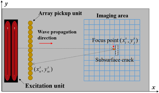
Schematic diagram of surface wave EMAT and SAFT.
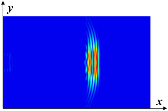
Snapshot of incident wave field.
In Eqs (2) and (3), the enhanced amplitude is related to the number of the pickup coils, the detection distance between pickup unit and target focus point, and the spacing of the pickup coils, in addition to the diameter and number of turn of the pickup coils. As the diameter of pickup coil d has to be taken as the wave length 𝜆 of the surface acoustic wave in order to make the motion induced eddy currents within a wavelength range being just superimposed [16], to enhance the signal amplitude I at focus point, the detection distance, spacing and number of coils have to be optimized.
An EMAT numerical code developed by authors based on the A-𝜙 formulation for eddy current simulation and a step by step time domain integration algorithm for particle vibration is adopted for the detectability evaluation and optimization of surface wave EMAT [17]. Numerical calculations are conducted for different detection distance, spacing and number of pickup coils in order to clarify their influence on the SNR of surface wave EMAT signals and SAFT imaging results. In simulation, the inspection target is selected as an aluminum rectangular plate of 150 mm × 110 mm × 8 mm size. A slit air region of 4 mm length, 4 mm depth and 0.2 mm width is set to the model as a typical subsurface crack. The crack is set at position 35 mm from the excitation unit and 0.5 mm beneath the upper surface of specimen as shown in Fig. 4. The excitation unit is chosen as two racetrack coils with length of 90 mm and width of 2.9 mm. The excitation unit is driven with pulsed sinusoidal current under bias magnetic field of 0.5 T flux density in vertical direction. The pulsed sinusoidal current has one cycle and its frequency f is 1 MHz. The array pickup unit consisting of 32 pancake pickup coils arranged densely in a row on the right side of the excitation unit is adopted to collect surface wave signals. As shown in Fig. 4, the center of the array pickup unit and the excitation unit are aligned with the center of the subsurface crack. The size of the finite element mesh is less than 𝜆∕10, and the calculation time step is less than 0.1∕f.
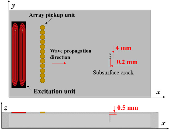
Schematic diagram of simulation model.
A rectangular area at specimen surface covering the subsurface crack is taken as the imaging area, and subdivided into a rectangular grid as shown in Fig. 2. A node in the grid just nearby the crack center is selected as the target focus point. Signals from two of the detection coils at typical location are simulated and compared in Fig. 5. Figure 5(a) shows the signal from coil located near the center of array unit, which is closest to the focus point, has stronger defect echo. While the defect echo almost cannot be recognized in the signal from the coil far away from the center of the array unit as shown in Fig. 5(b). In this way, the effective coil, i.e., the coil which can pick up the echo of target focus point efficiently, are numerically studied systematically.
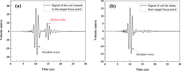
Signals from two coils with different distance from target focus point: (a) signal of coil near the center of array coils, (b) signal of coil far away from the center of array coils.
At first, the influence of number and the detection distance of effective coils are studied. Surface wave signals are calculated for array pickup unit at distances of 20.25 mm, 17.75 mm, 15.25 mm, 12.75 mm, 10.25 mm from the target focus point respectively. 32 surface wave signals measured with each detection distance are processed for selected target focus point by using the updated SAFT. The superimposed amplitudes at the target focus point with different number of coils and different detection distances are shown in Fig. 6. When the number of coils is enlarged over a certain number, the signal amplitude becomes saturated or even decreased. The SAFT processed signal results at different detection distances exhibit the same feature. This means that there is an optimized number of pickup coil as the ineffective coils will increased when total coil number is too large. The best number of effective coils at different detection distances between array pickup unit and target focus is shown in Fig. 7. The number of effective coils and the detection distance are linearly correlated in form of

Superimposed amplitudes vs. number of coils.
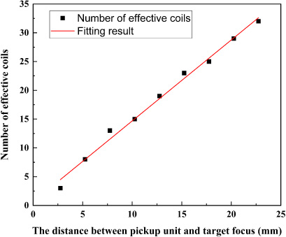
Number of effective coils at different detection distance.
Second, the influence of the coil spacing on the SAFT enhanced amplitude is investigated through numerical analyses. Surface wave signals due to array pickup EMAT of coil spacing (d, 2d, 3d, 4d, 5d, d is the coil diameter) are calculated with the code and model described above. The other parameters of the model are consistent with those used for different coil numbers given at the beginning of this subsection. Figure 8(a) to (c) give schematic diagrams of typical models for coil spacing 2d, 5d and 0.5d. As the size of excitation unit is given, the size of pickup coil and total region of pickup unit are fixed, i.e., different coil spacing means different number of pickup coils. The enhanced amplitudes resulted by using the updated SAFT based on signals from the array pickup coils with different coil spacing are given in Fig. 9. It can be found that a smaller coil spacing gives a better amplitude enhancement. Based on the results shown in Figs 7 and 9, we can find that large number of pickup coils and smaller coil spacing are prefer for the pickup unit to get better SAFT results.

Schematic diagrams of array pickup units with different coil spacing: (a) 2d, (b) 5d, (c) d∕2.

Enhanced amplitudes with different coil spacing.
Based on the simulation results above, an optimized array pickup EMAT of gap coil configuration is designed as that shown in Fig. 8(c). 32 pancake coils are densely arranged in two rows, each coil in one row is located at just the middle of the two coils in the other row. In this way, the coil spacing is reduced to half of the coil diameter. Figure 10 shows comparison of the SNR for surface wave signal results of single pickup coil (black line), the enhanced signal from the array unit with coil spacing d (blue line), and the enhanced signal from the array unit with gap configuration (red line). The enhanced signal with the optimized pickup unit EMAT gives the best SNR. It reveals that the combination of the optimized array pickup EMAT with gap configuration and the updated SAFT can further improve the SNR of defect signal echo. The gap configuration can efficiently reduce the coil spacing and increase the number of effective coils. In this case, the number of effective coils M becomes the summation of those in two coil rows, i.e.
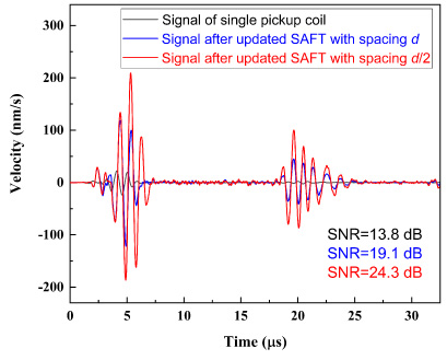
Comparison of SNR for different coil spacing.
The developed method is validated with simulated signals at first. Three numerical models with different subsurface cracks were built for cracks of 2 mm, 4 mm and 6 mm length respectively. The designed TR type array pickup EMAT of gap configuration and 32 detection coils is used to detect surface wave signals. The other parameters of models are consistent with those used in Section 2. The multiple signals from each coil of the array pickup unit are processed by using the updated SAFT. The enhanced imaging results of surface wave are illustrated in Fig. 11, where all the cracks can be clearly recognized. From the images, even the location and the length of the cracks can be properly measured with high precision. The detailed evaluation results of the 3 subsurface cracks are given in Table 1. The relative error is defined as the percentage of the absolute size difference of measured and true values in the total defect size. The error of 6 mm crack is a little larger than that of 4 mm crack, which may be caused by the relative larger grid size of the simulation model. Overall, the relative error is less than 5%, which gives good support to the validity and efficiency of the imaging algorithm and the surface wave EMAT system.

Enhanced imaging results of subsurface cracks.

Enhanced imaging result of 1 mm crack.
The location and length of three subsurface cracks
In addition, numerical simulations for a 1 mm length subsurface crack were also conducted to check the detectability of the developed method. Figure 12 shows the enhanced imaging result of updated SAFT, where the 1 mm subsurface crack can be recognized clearly from the image. The SNR comparison of defect echo is shown in Fig. 13. Comparing the enhanced signal with the signal from single pickup coil, the SNR of enhanced signal is improved about 15 dB, which is significant from signal imaging point of view. Therefore, it can be concluded theoretically that the developed imaging method can detect subsurface crack as small as 1 mm that is difficult for conventional method.
SNR comparison of 1 mm crack.
The validity and efficiency of the developed imaging method and optimized transducer is also demonstrated with measured surface wave EMAT signals. Based on the design given in Section 2, a prototype array pickup EMAT with gap configuration is fabricated to check its efficiency to obtain multiple surface wave signals and for further image processing with the updated SAFT. Figure 14 shows a photography of the prototype array pickup unit with 32 detection coils of 2.9 mm diameter. The coils are wound with enameled wire, and fixed in a flexible polyethylene board. The developed array pickup unit is adopted to acquire multi-channel signals of surface acoustic wave at each sampling time instant.
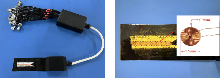
Photos of array pickup unit for surface wave EMAT.
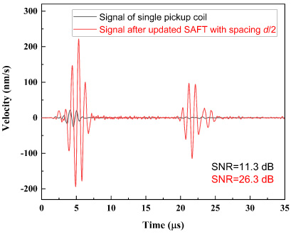
Figure 15(a) shows a photograph of the phased array EMAT system developed in author’s lab. The testing EMAT system includes a 16-channel excitation unit, a 32-channel receiving unit including filter, amplifier and A/D convertor, controlling/processing software and a computer. The maximum excitation voltage of each channel can reach 1000 Vpp, and the maximum sampling rate can reach 120 MS/s. The excitation module can drive excitation unit with 16 coils and realize phased array excitation. The receiving module has function of 32 channels signal receiving, i.e., and signals of 32 pickup coils can be collected and conditioned simultaneously. The excitation unit with 16 racetrack coils developed by authors in [14] is adopted for the transition of surface wave with 1 MHz. The excitation voltage is 800 Vpp, and the driving current amplitude in excitation coils is about 23 A. As shown in Fig. 15(b), an aluminum plate with 4 mm length subsurface crack located 145 mm from the excitation unit was inspected with the prototype transducer and the EMAT instrument. The size of the aluminum plate specimen is 450 mm × 200 mm × 20 mm. The crack was fabricated 0.5 mm beneath the upper surface of the test-piece plate with electrical discharge machining. The signals due to the crack are collected by using the array unit displayed in Fig. 14 and processed with the updated SAFT for signal enhancement and defect imaging. A magnet consisting of two pieces of permanent magnet is adopted to provide a horizontal bias magnetic field for the array pickup unit to detect surface wave signals. The imaging result with the measured signals is shown in Fig. 16, where the location and size of the subsurface crack can be properly recognized. The predicted length of crack is 4.3 mm and its location is assessed as 145.7 mm, which is of good agreement with the true values within an error less than 7%. Figure 17 displays the signals from a single pickup coil and the array pickup EMAT processed with the updated SAFT. Same as the case with simulated signals, the SNR is also significantly improved for the measured signals. All these results reveal that the proposed surface wave imaging method can improve the SNR and detectability of subsurface crack significantly.
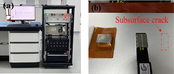
(a) EMAT experimental system and (b) specimen with excitation and pickup units.
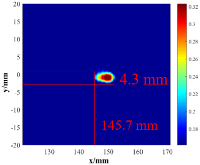
Experimental imaging result.
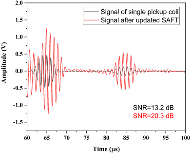
SNR comparison of experimental signals.
In this paper, an imaging method for multi-channel surface wave signals is proposed and validated to detect the subsurface defects in a metallic structure. The imaging algorithm is developed based on the SAFT for visualizing surface wave and improving the SNR of defect signal echo. In addition, the array pickup unit of gap configuration is optimized through numerical analyses by adjusting the number, spacing and detection distance of the pickup coil in order to get better surface wave signals and defect images. The proposed imaging method and developed array pickup EMAT are proved of high detectability and efficiency for detection and evaluation of subsurface cracks with both simulated and measured EMAT signals. It is proved with simulation results that a 1 mm subsurface crack can be properly detected by using the SAFT technique. In experiment, the fabricated 4 mm subsurface crack was clearly recognized, and its size and location were evaluated with almost the same high accuracy of the simulated results. In the future, the signal processing method and array pickup unit can be applied to detect delamination defects in coating structures of large attenuation of acoustic energy.
Footnotes
Acknowledgements
This work was supported by the National Science Foundation of China under Grant 11927801 and the National Major Science and Technology Project 2019-VII-0007-0147.