
Abstract
In this paper, a novel embedded double air gap electromagnetic hydraulic composite retarder (ED-EHR) is proposed. It has the advantage of high braking torque in the full-speed range compared with existing eddy current retarder, hydraulic retarder and electromagnetic hydraulic composite retarder (EHR) of the same size. However, the ED-EHR has the problem of mismatch between electric excitation and braking torque, i.e., the electric excitation is too large. In order to solve this problem, a multi-objective optimization design of the electromagnetic model (ED-EHR-E) of the ED-EHR is carried out with the objectives of minimum electrical excitation and maximum braking torque. Firstly, the working principle of the ED-EHR is introduced. Secondly, a multi-objective optimization method (FKNG-II) combining the full factorial design of experiment, the Kriging surrogate model (KSM), and the non-dominated sorting genetic algorithm II (NSGA-II) is established for the ED-EHR-E. Finally, the optimized the finite element analysis (FEA) results are compared with the FEA results and the experimental results of the initial design prototype. The results show that the optimized electrical excitation is reduced by about 29%, and the braking torque of the electromagnetic part is increased by 3%–16% in the full speed range. And the braking torque of the hydraulic part is increased by 10% by the optimization. In addition, the advantages of the ED-EHR are validated by comparison with the EHR.
Keywords
Introduction
With the development of auxiliary braking technology, auxiliary braking devices such as eddy current retarders (ECR) and hydraulic retarders (HR) are widely used in heavy-duty vehicles. They can consume most of the kinetic energy of the vehicle before friction braking, thus effectively improving driving safety and continuous braking performance [1–3]. Based on these advantages, retarders are increasingly favored by the industry. The ECR has high torque characteristics at low speed. And it has the advantages of short response time and simple control [4–8]. However, the thermal degradation caused by high temperature and the skin effect at high speed are unavoidable drawbacks of the ECR. The braking torque of the HR is directly proportional to the square of the speed, therefore it has the characteristic of high torque at high speed [9–13]. However, the long response time of the braking torque and insufficient torque at low speed are inherent defects of the HR. In 2020, our research team first proposed the electromagnetic hydraulic composite retarder (EHR), which addressed the shortcomings of the ECR and the HR. However, the EHR overamplifies the hydraulic part, resulting in low braking power in the full speed range [14].
This study proposes a novel embedded double air gap electromagnetic hydraulic composite retarder (ED-EHR). Compared with eddy current retarders, hydraulic retarders, and the EHR, in the same design space, it has the advantage of high braking torque in the full speed range. The ED-EHR consists of electromagnetic and hydraulic parts. In the full speed range, the ED-EHR mainly provides braking torque through the electromagnetic part, and the hydraulic part serves to compensate the braking torque and cool the electromagnetic part. However, the excessive electrical excitation leads to the problem of mismatch between electrical excitation and braking torque.
To solve this problem, the optimization method is crucial. The optimization objective of the ED-EHR is to minimize the electrical excitation and maximize the braking torque, which, however, encountered mutual conflict under limiting conditions. Some scholars have proposed to convert the multi-objective optimization problem into the single-objective optimization problem to reduce the processing difficulty [15–18], but this also leads to a significant reduction in the optimization accuracy. Multi-objective global optimization algorithms can achieve simultaneous optimization of multiple objectives. Common multi-objective global optimization algorithms include multi-objective particle swarm optimization [19], NSGA-II [20] and multi-objective efficient global optimization algorithm (MEGO) [21].
For the electromagnetic model (ED-EHR-E) of the ED-EHR, this paper establishes a multi-objective optimization method (FKNG-II) that combines the full factorial design of experiments (FFD), the kriging agent model (KSM), and the non-dominated sorting genetic algorithm II (NSGA-II). The electrical excitation of the optimized ED-EHR is reduced and the braking torque is improved. The rest of the paper is organized as follows. Section 2 describes the working principle of the ED-EHR. Multi-objective optimization of the ED-EHR-E is performed in Section 3. Section 4 presents the comparative analysis between the optimization results and the 3D-FEM analysis results and experimental results of the initial design prototype, and verifies the advantages of the ED-EHR by comparing with the ECR, HR and EHR. Section 5 summarizes the paper.
Structure and principle
The structure of the ED-EHR is shown in Figure 1. The electromagnetic part and hydraulic part are arranged radially, and the hydraulic part is integrated into the inner ring of the electromagnetic part. The excitation coil is wound on the inner side of the stator slot to provide a constant annular magnetic field


The ED-EHR structure diagram.
The hydraulic part uses hydraulic oil as the working medium. The hydraulic oil flows from the hydraulic part to the electromagnetic part to cool it down, which further inhibits its thermal degradation. The main specifications of the electromagnetic part of the initial experimental prototype of the ED-EHR are shown in Table 1.
Main specifications of the ED-EHR-E.

During the working process, the excitation coil of the ED-EHR is energized, and hydraulic oil enters the hydraulic part through the inlet. The electromagnetic part generates the braking torque that hinders the rotation of the rotor. At the same time, the rotor drives hydraulic oil circulation and vortex flow to impede rotor movement. According to the principle of conservation of energy, the kinetic energy of the rotor is converted into Joule heat by the electromagnetic part, and the other part is converted into the thermal energy of hydraulic oil by the hydraulic part. The hydraulic oil flowing out from the outlet is cooled by the radiator and returned to the oil tank. It can be seen from this that the braking torque of the ED-EHR is equal to the sum of the braking torque of the electromagnetic part and the hydraulic part.
The optimization flowchart is shown in Figure 2. In general, the optimization process can be summarized as follows.

The optimization flow chart of the ED-EHR-E.
Step 1: Construct optimization model. Determining the optimization objective and design parameters are included in the step. The electrical excitation of the initial design prototype is too large, resulting in the mismatch between the electrical excitation and the braking torque. Therefore, the minimum electrical excitation and the maximum braking torque are set as optimization objectives. Next, the optimization variables are determined according to the basic law of magnetic circuit and the working principle of the ED-EHR-E.
Step 2: Establish surrogate model. Based on the optimization model established in Step 1, the full factorial DOE incorporating 3D-FEM is used to establish surrogate model. Based on this, the KSM is established, and the comparative analysis using the stepwise regression surrogate model (SRSM) and the neural network surrogate model (NNSM) is conducted to verify the accuracy and effectiveness of the KSM.
Step 3: Multi-objective optimization. Two optimization algorithms NSGA-II and MEGO are established in the step. They are optimized iteratively with KSM to obtain the corresponding Pareto front solutions respectively. The superiority of NSGA-II is verified through comparative analysis.
Step 4: Performance Evaluation. Firstly, the static magnetic flux density and air-gap magnetic density of the optimized and initial design prototype are compared respectively to illustrate the advantages of the optimized ED-EHR-E in principle. Finally, the braking torque of the optimized and initial design prototype at different speeds are compared to verify the advantages of the optimized ED-EHR.

Design parameters of the ED-EHR-E.
The simplified ED-EHR-E model is shown in Figure 3. In the previous study, it is known that the increase of the excitation coil part will make the electrical excitation stronger, but the oversized excitation coil will cause the increase of the outer diameter R2, the decrease of the inner diameter R3 and the decrease of the left side width H2 of the stator slot, which will eventually lead to the increase of the stator reluctance. Excessive outer diameter R7, inner diameter R8 and tooth width H6 of the rotor teeth will cause the stator reluctance to increase and the electrical excitation F to become smaller. In addition, the increase of the upper tooth thickness W1 and the lower tooth thickness W2 of the rotor will cause the serious leakage of magnetic flux between the rotor and the stator. Meanwhile, the optimization objectives of this paper are to reduce the electrical excitation F and increase the braking torque T as much as possible, so the coil width H4, rotor tooth width H6, rotor tooth outer diameter R7 and rotor upper tooth thickness W1 are set as optimization parameters and defined as independent variables.
The inner diameter R3 and outer diameter R2 of the stator slot are changing as the inner diameter R8 and outer diameter R7 of the rotor teeth change. When the inner diameter R3 and outer diameter R2 of the stator slot are changed, the inner diameter R6 and outer diameter R5 of the excitation coil are changed accordingly. The change in excitation coil width H4 and rotor tooth width H6 causes the change in stator slot left side width H2. The lower tooth width H7 and the lower tooth thickness W2 of the rotor change with the upper tooth width H6 and the upper tooth thickness W1. Therefore, the inner diameter R3, outer diameter R2 and left side width H2 of the stator slot, inner diameter R6 and outer diameter R5 of the excitation coil, inner diameter R8 of the rotor teeth, lower tooth width H7 and lower tooth thickness W2 are designed as dependent variables.
The total width H1, outer diameter R1 and inner diameter R4 of the stator are space boundary constraints, that is, the dimensions of the initial prototype. The distance H3 between the excitation coil and the left side of the stator slot, the distance H5 between the excitation coil and the rotor teeth, the upper and lower air gaps g1, g2, and the outer diameter R9 and inner diameter R10 of the connecting bars between the rotor teeth are used as constants. Structural parameters and initial values of the ED-EHR-E are shown in Table 2. The principle of the range of values of the independent variables is that when the maximum and minimum values are taken, there is no interference between the parts.
Structural parameters and initial values of the ED-EHR-E.
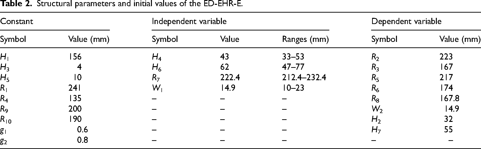
Structural parameters and initial values of the ED-EHR-E.
The optimization model can be defined as follows:
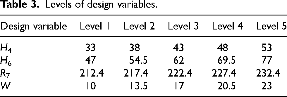
Levels of design variables.
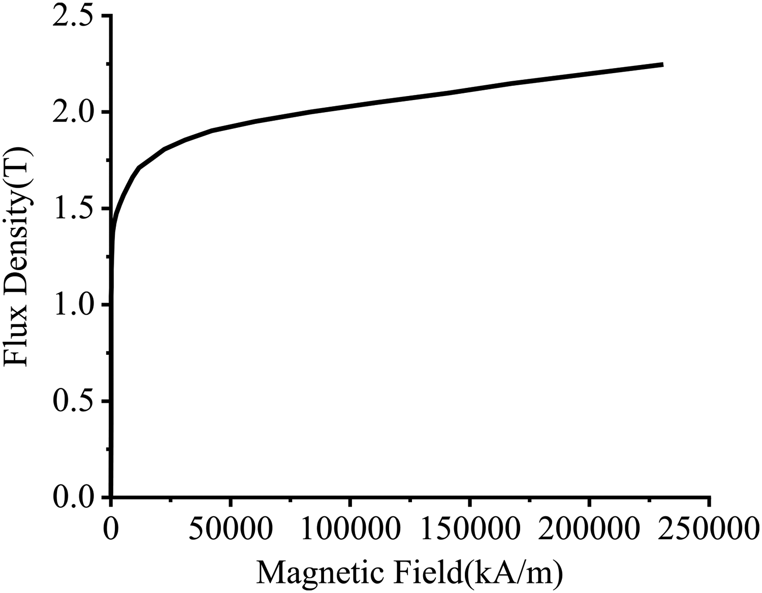
The B-H curve of 20# steel.
At present, the main DOE methods commonly used are full factorial design (FFD), central composite design (CCD) and Latin hypercube design (LHD). The FFD allows all combinations of all variables to be experimented at least once at all levels, and main effects and interaction effects can be calculated for all variables. Compared to other DOE methods, FFD can be used to obtain accurate and reliable results when there are few variables [22]. In this study, the FFD method incorporating the 3-D FEM (FF-FM) is used to establish the sample data space. The ED-EHR-E includes 4 independent variables, each variable level being defined as 5, so there are a total of 625 sample points. Then, the 3-D FEM is used to solve the sample points, and finally the sample data space is established. Table 3 shows the levels of the design variables. The DOE project is constructed using the multi-objective optimization software modeFRONTIER2020. Each sample point is solved using the electromagnetic simulation software JMAG-Designer17.1. The material of the stator and rotor is 20# steel. During the solution process, the conductivity of the material is set to 4 MS/m. The B-H curve of the material is shown in Figure 4.
In order to determine the impact of design parameters on the optimization objectives, the sensitivity index S (x, y) is introduced to measure the impact of design parameter x on the optimization objective y.
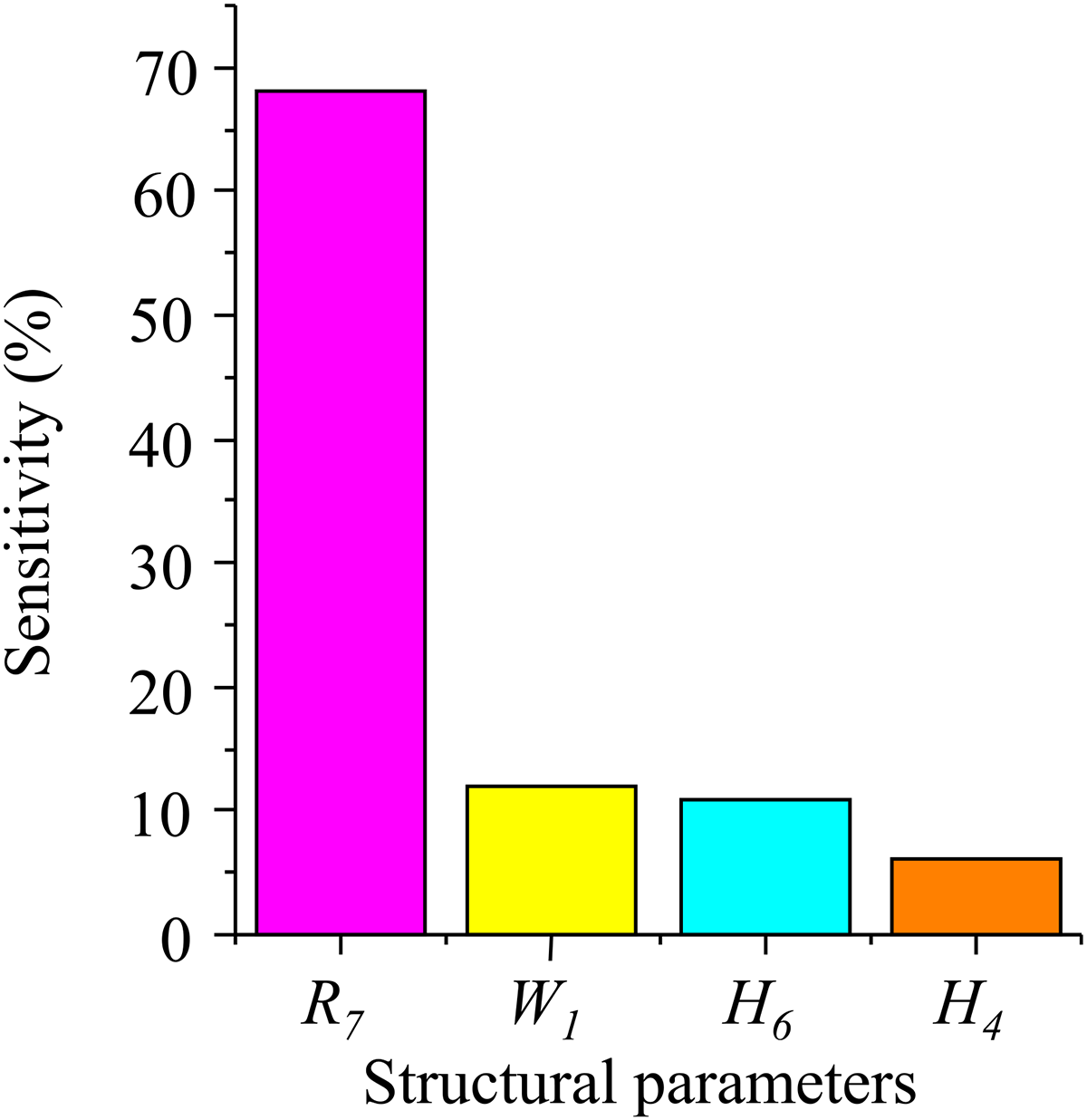
Sensitivity analysis results.

The KSM verification.
The sensitivity analysis is shown in Figure 5. The sensitivity value reflects the degree of influence of the design parameters on the optimization objective. From the figure, it can be seen that the outer diameter R7 of the rotor teeth has the greatest impact on the braking torque, followed by the rotor teeth thickness W1 and the rotor teeth width H6. This provides experience and basis for future design.
Surrogate models can be used as the alternative to FEM, thereby reducing the computational burden. In the process of multi-objective optimization, the relationship between the objectives and the optimized parameters can be represented by a surrogate model. For an input x, the response Y (x) of the KSM can be expressed as:


The ED-EHR-E is trained on the sample data space established by the FF-FM to obtain the KSM of the braking torque. In order to verify the accuracy and superiority of the KSM, the validation datasets with partial samples are established for the ED-EHR-E through the FF-FM, and the SRSM and the NNSM are also created for comparison. Figure 6 shows the response surface model of the KSM, the SRSM, and the NNSM. The REAL represents the results of the 3D-FEM simulation. As can be seen from the figure, the results of the KSM prediction are more consistent with the results of the 3D-FEM simulation.
Levels of design variables.

Response surface view of the KSM.
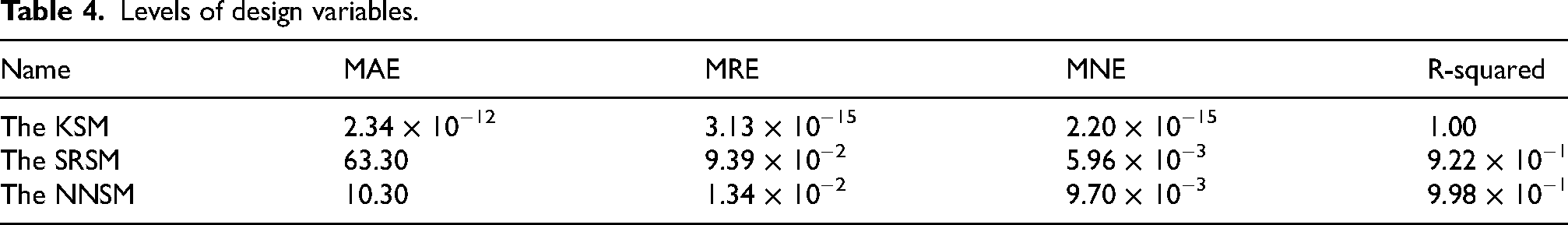
The mean absolute error (MAE), mean relative error (MRE), mean normalized error (MNE), and R-squared of the three surrogate models are shown in Table 4. As can be seen from the table, the MAE, MRE, and MNE of the KSM are the smallest, and the R-squared is 1, which indicates that the predicted results of the KSM have high accuracy and strong generalization ability.

Flow chart of the NSGA-II.
Figure 7 shows the response surface view of the KSM, which shows that all response surfaces have high gradients. Figure 7(a) shows the relationship between the outer diameter R7 and the tooth width H6 of the rotor teeth and the braking torque T. Figure 7(b) represents the relationship between the rotor tooth thickness W1 and the excitation coil width H4 and the braking torque T. From the figure, it can be seen that the braking torque T exhibits the non-linear relationship with the design variables. Therefore, the maximum value of the braking torque T can be achieved only in the range of the appropriate variable area.
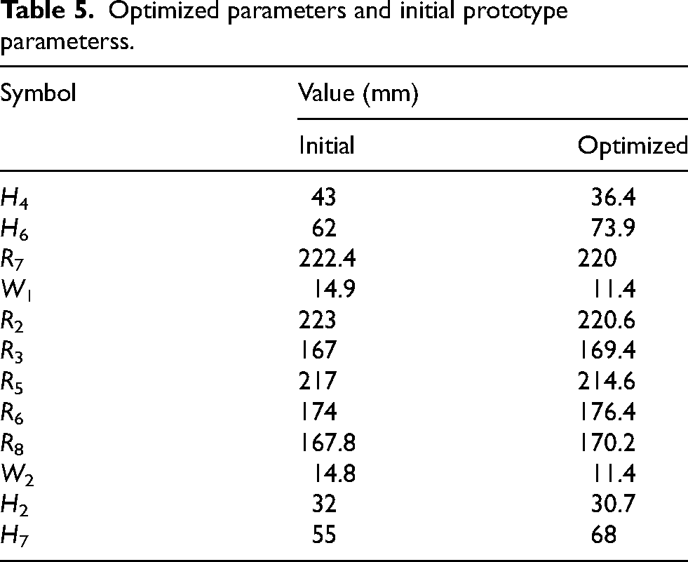
The multi-objective optimization work is completed in the multi-objective optimization software modeFRONTIER2020. The NSGA-II processes constraints by applying the constraint dominance algorithm in the software. The constraint dominance algorithm follows the following principles: (1) feasible designs are ranked according to the Pareto dominance criteria. (2) Feasible designs are always ranked better than unfeasible designs. (3) Unfeasible designs with a lower sum of constraint violations are ranked better than those with a higher overall constraint violation. The flowchart of the NSGA-II is shown in Figure 8. Based on experience, the parameters involved in the algorithm are set as follows: population size set to 5000, algebra set to 500, crossover probability and mutation probability set to 0.95 and 0.4, respectively. Figure 9 shows the optimization results and the Pareto front solutions obtained by the NSGA-II for two optimization objectives. The D1 point in the figure is the optimal point selected according to the optimization objectives, which represents the braking torque of 1545 Nm and the electrical excitation of 10570 AT. The design parameters represented by the D1 point and the initial prototype parameters are shown in Table 5.

Optimization results and the Pareto front solutions obtained by the NSGA-II.
Optimized parameters and initial prototype parameterss.

Optimization results and the Pareto front solutions obtained by the MEGO.
In order to verify the superiority of the NSGA-II, the MEGO is specifically introduced for comparison. The MEGO is a surrogate-assisted multi-objective optimizer based on Gaussian Processes. It can effectively solve design optimization problems under multiple constraint conditions and significantly reduce computational time compared to traditional algorithms [21]. The parameters settings of the MEGO are the same as the NSGA-II. Figure 10 shows the optimization results and the Pareto front solutions obtained by the MEGO for two optimization objectives. D2 point is the optimal point, representing the braking torque of 1524 Nm and the electrical excitation of 10570 AT. Under the same electrical excitation conditions, the braking torque obtained using the NSGA-II is greater than that obtained using the MEGO. Moreover, it can also be seen that the convergence and diversity of the Pareto front solutions obtained by the NSGA-II are better than those obtained by the MEGO. In addition, the time required for the MEGO is approximately 30 min. The time required for the NSGA-II is about 5 min. Therefore, it can be seen that the NSGA-II is superior to the MEGO.
To verify the effectiveness of the multi-objective optimization, the 3D-FEM simulation is conducted based on initial and optimized design parameters using the JMAG-Designer17.1, and the optimized simulation results are compared with the simulation results and the experimental results of the initial design prototype. Furthermore, the braking performance and the electromagnetic characteristics of the ED-EHR-E are evaluated.
Figure 11(a) shows the static magnetic flux density cloud map of the ED-EHR-E under the initial design parameters. Figure 11(b) shows the static magnetic flux density cloud map of the optimized ED-EHR-E. From the figure, it can be seen that after optimization, the volume of the excitation coil and stator slot is significantly reduced, the width H6 of the rotor teeth, and the thickness of the upper and lower parts of the stator are significantly increased, which makes the magnetic field distribution more uniform. From Figure 12, it can be seen that after optimization, the air gap magnetic flux density of the ED-EHR-E has increased from 2 T to 2.08 T, which is conducive to generating greater eddy current braking force.

Contours of magnetic flux density of the ED-EHR-E.

Static air gap magnetic flux density of the ED-EHR-E.
The values of R
i
and R
o
in Figure 11 are 145 mm and 148 mm, respectively. They represent the outer radius of the hydraulic part of the initial design and optimized the ED-EHR-E. The R
o
is 3 mm larger than the R
i
. The braking torque of the hydraulic part can be obtained by the following formula [23]:
It can be seen from (9) that after optimization, the braking torque of the hydraulic part has increased by about 10%.
Figure 13 shows the air gap magnetic flux density of the initially designed the ED-EHR-E and optimized the ED-EHR-E at 1000 r/min. From the figure, it can be seen that the air gap magnetic flux density has also increased.

The air gap magnetic flux density of the ED-EHR-E at 1000 r/min.
Figure 14 shows the bench experiment of the initial design prototype. Figure 14(a) shows the composition of the experimental bench. Figure 14(b) shows the ED-EHR. Figure 14(c) shows the experimental bench, mainly composed of a drive motor, gearbox, transmission shaft, and the ED-EHR. The ED-EHR is installed in the gearbox. A torque sensor is installed between the gearbox and the drive motor, and the measuring device records torque in real-time. The excitation coil of the ED-EHR is powered by a 24 VDC power supply, and the inlet flow rate of the hydraulic section is 2 LPS. During the experiment, the braking torque is first tested when the excitation current is 0, and the result obtained is the braking torque of the hydraulic part. Secondly, the braking torque of the ED-EHR is tested by applying a current of 100 A to the excitation coil, at which time the electric excitation is 14900 AT. The braking torque of the electromagnetic part is equal to the difference between the braking torque of the ED-EHR and the braking torque of the hydraulic part.

Bench test of the initial design prototype.
Figure 15 shows the comparison of the braking characteristics between the initial design ED-EHR-E and the optimized ED-EHR-E at different speeds. When the speed is below 1000 r/min, the experimental results of the initial prototype are higher than the 3D-FEM calculation results of the initial prototype, and there is a certain error between them. The maximum error is about 10%. When the speed is higher than 1000 r/min, the experimental results are in good agreement with the 3D-FEM calculation results. Overall, the experimental results have certain reference value.

The comparison of braking characteristics between the initial design prototype and the optimized ED-EHR-E at different speeds.
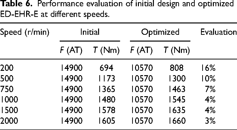
After optimization, the electrical excitation F of the ED-EHR-E decreased from 14900 AT to 10570 AT, a decrease of 29%. It can be observed from the figure that the braking torque at different speeds has increased through optimization. The comparison of the 3D-FEM calculation results of the initially designed ED-EHR-E and the optimized ED-EHR-E is shown in Table 6. Within 500 r/min, the braking torque has increased by more than 10%. As the speed increases, the proportion of increase gradually decreases, increasing by 3% at 2000 r/min. From the above analysis, it can be seen that the matching of the electric excitation and the braking torque of the optimized ED-EHR-E is more reasonable.
The optimized ED-EHR prototype is not fabricated due to the good agreement between the 3D-FEM calculations and experimental results of the initial design prototype of the ED-EHR, as well as considering the cost of the experiment. The comparison of the braking torque and the braking power of the ED-EHR, the HR, the EHR and the ECR of the same size is shown in Figure 16. As can be seen from the Figure 16(a) and Figure 16(b), at high speed, the braking torque and braking power of the optimized ED-EHR increase significantly. Compared with the EHR, the HR and the ECR, the ED-EHR has a larger braking torque and braking power in the full speed range.
Performance evaluation of initial design and optimized ED-EHR-E at different speeds.

Comparison of the braking torque and power for the ED-EHR, the EHR and the ECR of the same size.
For the problem of low braking power in the full speed range of the existing eddy current retarder, the hydraulic retarder and the EHR, this paper proposes a novel ED-EHR with high braking power in the full speed range. In order to match the electrical excitation and the braking torque of the ED-EHR more reasonably, a multi-objective optimization method (FKNG-II) combining the FFD, the KSM, and the NSGA-II is established with the optimization objectives of the minimum electrical excitation and maximum braking torque. During the optimization process, the accuracy of the KSM is verified by comparing with the SRSM and the NNSM. And the MEGO is introduced to validate the accuracy of the NSGA-II. The optimization results are compared with the 3D-FE calculation results and experimental results of the initial design prototype. The results show that the optimized electrical excitation is reduced by about 29% and the braking torque of the electromagnetic part is increased by 3%–16% in the full speed range. In addition, the braking torque of the hydraulic part is increased by 10% after optimization. Finally, the advantages of the ED-EHR in the full speed range are verified by comparing with the EHR and the ECR.
Footnotes
Acknowledgement
This work was supported by the Beijing Natural Science Foundation under Grant 3212028.