
Abstract
This paper conducts the structural design and a fuzzy PID control for the hybrid excitation eddy current recoil absorber (HE-ECRA) aimed at mitigating the impact of instantaneous intensive load on the artillery mount. Firstly, a structurally simpler HE-ECRA is designed to replace the traditional hydraulic recoil absorber. It not only circumvents issues such as liquid leakage and maintenance difficulties associated with the traditional hydraulic structure but also enables real-time control of resistance. Subsequently, equivalent subdomain (analytical) and finite element models are established for the HE-ECRA. By inputting the artillery launch load, the operational performance, as well as the relationship between structural parameters and the resistance law, are investigated. Finally, a stable resistance control method for the HE-ECRA based on a fuzzy PID strategy is proposed. A co-simulation platform was developed to facilitate bidirectional dynamic data transmission between the recoil motion parameters and excitation current. The research indicates that the controlled HE-ECRA can mitigate the ’saddle’ effect, enhance the stability of recoil resistance, and reduce the impact effect of launch load on the artillery mount. This paper provides a universal buffering solution for structures subjected to transient high-impact loads and offers a feasible method for real-time resistance control.
Keywords
Introduction
Artillery is a core weapon system that safeguards national territory and addresses wartime threats. When the artillery is fired, the gas pressure generated by the burning artillery powder in the barrel propels the projectile forward while causing the barrel to move backward, i.e., recoil motion [1]. The instantaneous intensive impact load acts on the artillery frame through the recoil absorber, causing the artillery frame to flip, jump, etc. action. Increasing the projectile’s kinetic energy inevitably worsens the stability of the artillery carriage. A high-performance recoil absorber is an effective way to solve this issue [2,3]. Essentially, the recoil absorber is an enegy-absorbing buffering device. Enhancing the stability of mechanical systems under load using buffering devices is also a significant area of research in mechanical engineering [4–6].
Traditional hydraulic buffering devices for artillery have complex structures, are difficult to maintain, and may experience issues such as fluid leakage and cavitation effects during long-term use. Additionally, accurately calculating the resistance characteristics is also a challenging task. To solve these problems, electromagnetic buffering devices, which have a higher energy dissipation rate and lack liquid components, have emerged as a solution [7,8]. According to the different primary excitation sources, electromagnetic dampers can be divided into three types: permanent magnet type [9–11], electromagnet type [12], and hybrid excitation type [13]. In the hybrid excitation eddy current recoil absorber (HE-ECRA), the magnetic field at the air gap is produced by both permanent magnets and excitation windings. This design combines the advantages of both permanent magnet and electromagnet types, mitigating performance degradation caused by demagnetization effects [14,15] while avoiding issues such as large size and complete failure in case of power loss. However, the HE-ECRA has various structural forms, each with its own magnetic circuit distribution and resistance characteristics. Currently, there is no mature design theory system for this technology.
In the study of hybrid excitation electromagnetic dampers, Reza et al. [16] designed a hybrid excitation radial magnetic flux eddy current recoil absorber using a magnetic equivalent circuit. They investigated the influence of air gap length and conductor plate on the resistance characteristics. Wang et al. [17] proposed a new V-shaped hybrid excitation electromagnet for low-speed magnetic levitation trains and calculated the force characteristics considering the influence of eddy currents at different velocities. Sang et al. [18] introduced a dual-sided hybrid excitation eddy current damper to suppress the vibration of a linear motor during the decelerating and stopping stages. Li et al. [19] developed a hybrid excitation rail eddy current brake system based on the principle of electromagnetic fields, aimed at meeting the safety and reliability needs for large braking power consumption in high-speed trains. However, the analytic methods for hybrid excitation eddy current dampers predominantly rely on the equivalent magnetic circuit method, which cannot accurately calculate the magnetic field intensity at high velocities. Thus, it is not suitable for recoil motion in artillery. Therefore, in this study, the equivalent magnetic circuit method is used to calculate the magnetic field magnitude at the air gap. Then, a subdomain model is employed to calculate the electromagnetic damping force [20,21].
The main control strategies used in electromagnetic dampers include fuzzy control [22–25], sliding mode control [26], neural network control [27], and others. Fuzzy control, in particular, does not require accurate analytical models and can effectively compensate for the effects of end-effects, magnetic saturation, skin effect, and other phenomena impacting the electromagnetic damper. Arunesh et al. [22] developed a fuzzy controller to improve the braking performance of eddy current brakes for high-speed operating systems. He et al. [23] designed a fuzzy controller to enhance the response speed of an eddy current hydraulic hybrid brake system and reduce the wear and temperature of the brake disc. Qi et al. [24] proposed a fuzzy control method for eddy current braking based on an ideal braking curve, achieving the goal of stopping the train within a specified range. Cao et al. [25] designed an adaptive controller with fuzzy logic systems for an electromagnetic actuator servo system to address the stability problem of a vehicle suspension under stochastic disturbance.
This paper highlights three main contributions. Firstly, it introduces the structural form of a hybrid excitation eddy current brake and performs a magnetic circuit analysis. The expression for electromagnetic resistance is derived by establishing an equivalent subdomain model. A finite element model is developed to validate its accuracy. Secondly, based on the firing load of the artillery, a preliminary design of the HE-ECRA is conducted using the analytical model. Its performance is analyzed, and the influence of structural parameters on resistance characteristics and recoil displacement is investigated, laying the groundwork for structural optimization. Thirdly, a fuzzy PID control strategy is proposed for the HE-ECRA to mitigate the effects of magnetic saturation and demagnetization on damper performance. Bidirectional dynamic data transmission between recoil motion parameters and magnetic current is achieved by establishing a co-simulation model. The results demonstrate that energy consumption during recoil and the stability of the resistance are improved through real-time control.
Design and modeling of the hybrid excitation eddy current recoil absorber
Structural design
The HE-ECRA designed in this paper can be regarded as a dynamic primary-type linear electromagnetic damper. Figure 1 illustrates its structural configuration, which consists of a primary and a secondary component. The primary component includes the brake rod, excitation coil, permanent magnet, and magnetic shoe, while the secondary component comprises the inner cylinder and outer cylinder. The coil and permanent magnet are coaxially arranged between the magnetic shoes. The coil is wound on the inner side of the brake rod, with adjacent coils having opposite current flow directions. The permanent magnets are positioned on the outer side and magnetized along the axial direction, with adjacent magnets having opposite polarities.
The HE-ECRA structure schematic.
According to Lenz’s Law, when the artillery experiences recoil, a relative motion occurs between the primary and secondary parts. This relative motion generates electromagnetic forces on the secondary component, which acts to oppose its movement.
The magnetic induction line distribution of the HE-ECRA is illustrated in Fig. 2. The magnetic flux path generated by the coil consists of the main circuit: brake rod - magnetic shoe - air gap - inner cylinder - outer cylinder - inner cylinder - air gap - magnetic shoe - brake rod, and the secondary circuit: brake rod - magnetic shoe - coil - magnetic shoe - brake rod. The magnetic flux path generated by the permanent magnet is: permanent magnet - magnetic shoe - air gap - inner cylinder - outer cylinder - inner cylinder - air gap - magnetic shoe - permanent magnet. The magnetic fields generated by the coil and the permanent magnet converge at the magnetic shoe’s end, increasing the magnetic field density at the air gap.
Magnetic induction line distribution.
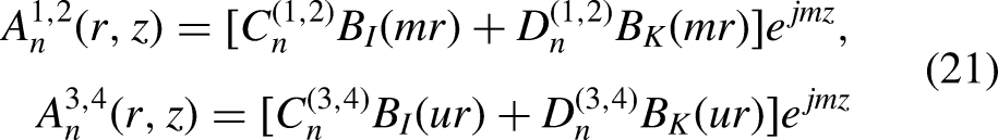
The equivalent subdomain method is adopted to derive the analytical model of the HE-ECRA. First, the magnetic field in the air gap under static conditions is analyzed. Considering the schematic diagram of magnetic flux direction within one pole pitch, as shown in Figs 3 and 4, along with its equivalent magnetic circuit.
Schematic diagram of magnetic flux flow direction.
Where, τ is the pole pitch. b is the axial thickness of the permanent magnet. c is the axial thickness of the magnetic shoe. r1 is the inner diameter of the coil. r c and r pm refer to the inner and outer diameters of the permanent magnet, respectively. r mb is the outer diameter of the magnetic shoe. r ag and r cp refer to the inner and outer diameters of the inner cylinder, respectively. r bi is the outer diameter of the outer cylinder.

Equivalent magnetic circuit diagram.
Then, the calculation equations for each element in the equivalent magnetic circuit model are provided.
The amperage-turns of the excitation coil is

The magnetic potential of the permanent magnet is
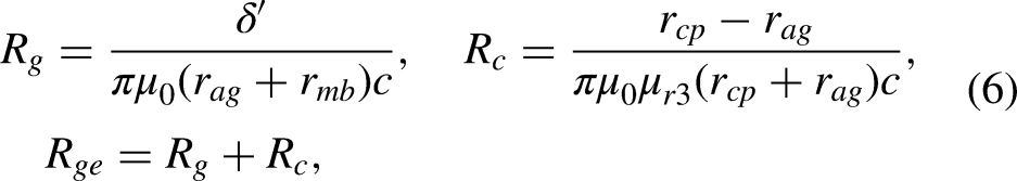
The magnetic resistance of each part is
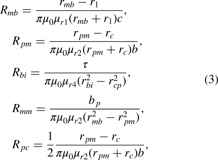
Considering that the structure of the HE-ECRA has grooves, the air gap length δ needs to be corrected using the Carter coefficient K
c
[28]. The revised air gap length is


According to the superposition principle, the magnetic flux for the individual effects of the permanent magnet, coil, and eddy current can be separately solved, and then combined to obtain the total magnetic flux.
When the permanent magnet acts alone,
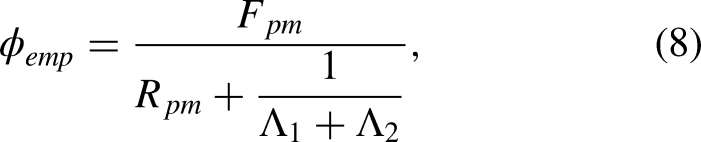
When the coil acts alone,

When the eddy current acts alone,
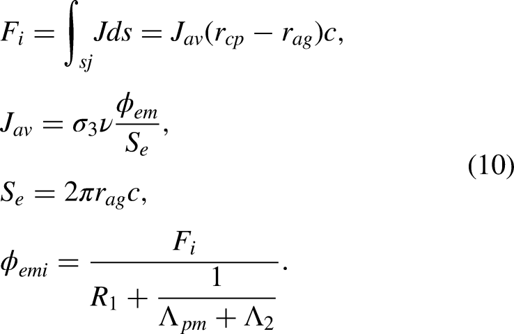
Then, the total magnetic flux is

To reduce the complexity of the subdomain model, a simplification of the HE-ECRA is performed, as shown in Fig. 5. According to the equality of magnetic potentials, the coil and the permanent magnet are equivalently represented as an infinitely thin current layer on area 1. The following assumptions are made for ease of analysis:
(1) All four areas are infinitely long in the x-direction. Eddy currents are only generated in the inner cylinder, and the skin effect is not considered.
(2) The magnetic induction intensity in the air gap is constant in the z-direction, and end effects are neglected.
(3) The relative permeability between the inner cylinder and the permanent magnet is assumed to be 1.

Subdomain model.
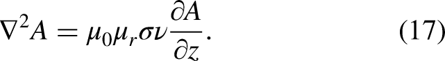
According to Maxwell’s equations, we have

Since the conductivity at the equivalent area and the air gap is 0, it can be obtained from Eq. (13),


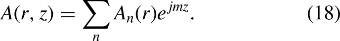
Assuming that the electromagnetic quantities in the subdomain model are periodic functions with a period of 2τ, then
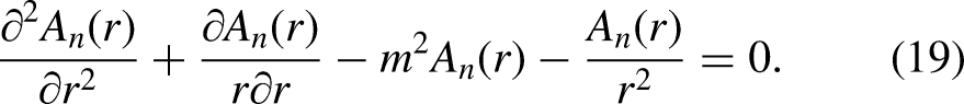

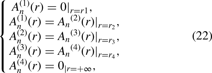
Solving Eqs (19) and (20), we have,
The values of

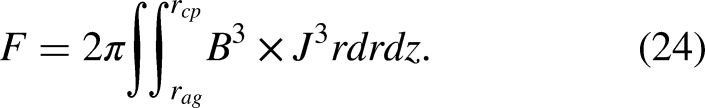
Therefore, the expression for electromagnetic damping force at the inner cylinder is
In the calculations that follow, a shooting angle of 0° is used unless otherwise stated.
Figure 6 illustrates the finite element model of the HE-ECRA, which is established to validate the accuracy of the analytical solution (24). The specific structural parameters are shown in Table 1. The HE-ECRA designed in this paper has a rotationally symmetric structure. Therefore, a two-dimensional axisymmetric calculation model is selected.

Finite element calculation model.
The results of the calculations for both models are shown in Figs 7–9. Figure 7 depicts the distribution of magnetic induction lines when the system moves at different velocities. It can be observed that the magnetic induction lines are guided by the magnetic shoes and enter the inner cylinder through the air gap. As the velocity increases, the tilt angle of the magnetic induction lines also increases, accompanied by a certain degree of reduction in the magnetic field strength at the inner cylinder. The reason is that with higher velocity, the armature reaction becomes stronger, leading to a greater weakening effect on the main magnetic field and a more pronounced tilt of the magnetic induction lines.
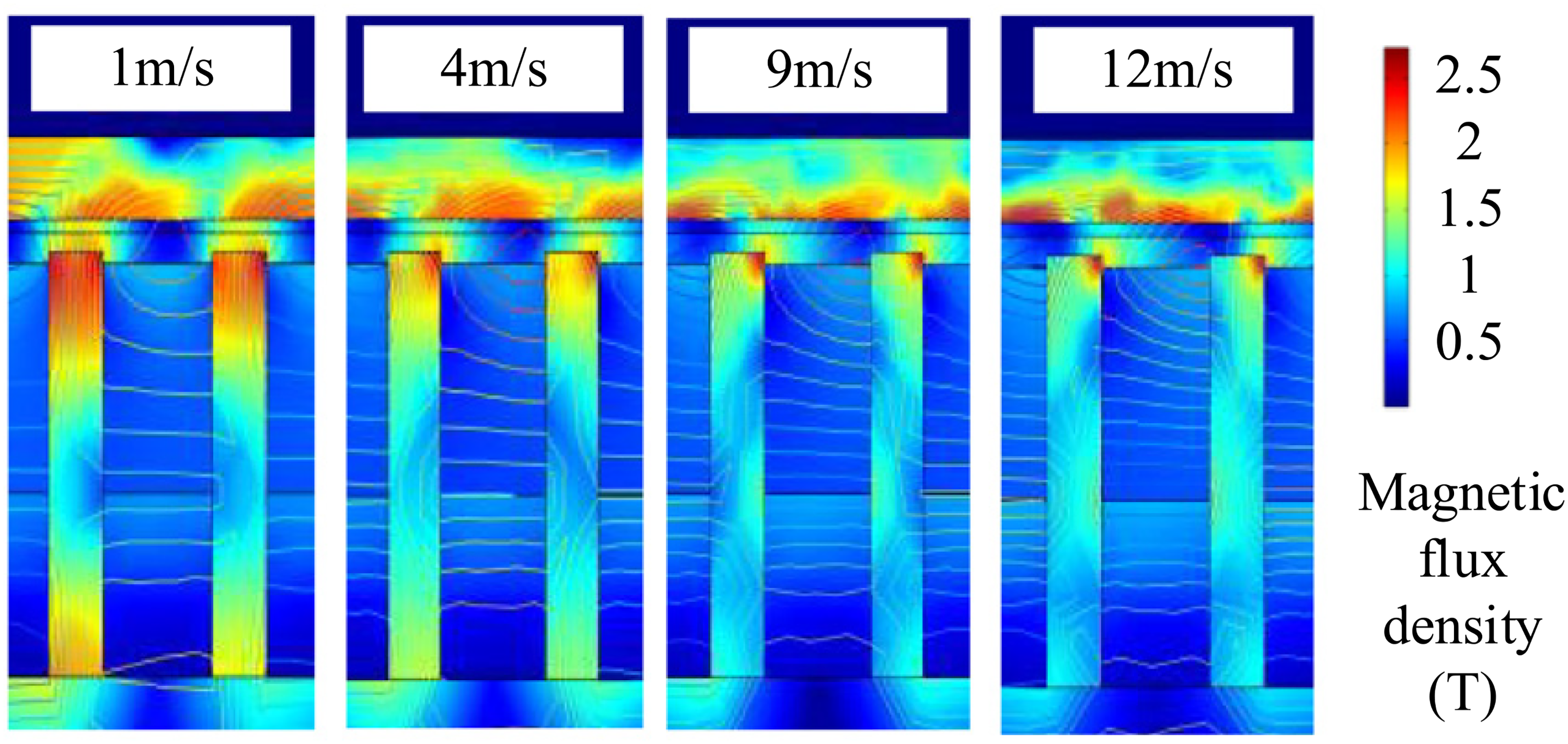
Magnetic field distribution at different velocities.
Analyzing Fig. 8, it can be obtained that the results of the radial magnetic induction intensity at the inner cylinder calculated by both models are in good agreement. The analytical model can accurately describe the electromagnetic characteristics of the HE-ECRA in static conditions.
Main specifications of the HE-ECRA.

The relationship between electromagnetic damping force and velocity is shown in Fig. 9. The analytical model neglects phenomena such as armature reaction and magnetic saturation, which can lead to solving errors when compared to the finite element model. But, the maximum error of 5.78% falls within an acceptable range. Additionally, it is found that once the velocity reaches a critical value, the electromagnetic damping force does not continue to increase with further velocity increment. This also provides a basis for structural design.
Radial magnetic induction at the inner cylinder as a function of position.

The relationship between electromagnetic damping force and recoil velocities.
Recoil motion analysis
For a specific artillery firing load, the resistance characteristics of the HE-ECRA during operation are analyzed in this subsection. The layout diagram of the HE-ECRA and the force analysis during artillery firing as Fig. 10. The HE-ECRA is installed on the cradle and has a gap between the barrel. When the barrel undergoes recoil motion due to the resultant force F pt , the HE-ECRA generates a resistance force F e , and the recuperator generates a resistance force F f . At the same time, the front and rear liners provide support force FN1 and FN2, and generate frictional force. Here, Q0 is gravity, f represents the friction coefficient. φ0 denotes the firing angle, and e represents the eccentricity distance.
The resultant force in the bore curve during recoil process and the recuperator force curve are shown in Fig. 11. The calculation recoil displacement, velocity and electromagnetic damping force curves for the HE-ECRA are shown in Figs 12–13.
It can be concluded that under the action of the HE-ECRA, the artillery recoil displacement is 900 mm, which meets the operational requirements of the artillery.

Resultant force curve.
Resultant force and recuperator force.
Recoil displacement and velocity profile.
Electromagnetic damping force curve.
The maximum recoil velocity is 12.7 m/s, which is lower than the critical velocity. Therefore, the operation of the HE-ECRA is reliable.
The analytical model and finite element solution exhibit similar trends, but there is a significant difference in their maximum values. This is because the analytical model is fitted based on the values Fig. 9, and the velocity changes are relatively smooth. As a result, the variation of the electromagnetic damping force appears smoother. When using the finite element model for calculations, the recoil velocity can experience a sudden increase, resulting in an instantaneous enhancement of the electromagnetic damping force. This, in turn, intensifies the armature reaction and leads to a rapid decrease in the electromagnetic damping force. Consequently, the characteristic ‘saddle’ shape shown in Fig. 13 is formed. Although there are local differences, the damping force curves, the work done by the damper, and the recoil displacement indicators calculated by both methods are approximately similar. Therefore, the analytical model is credible and convenient during the theoretical analysis and structural design phases.

Percentage of recoil energy consumption at different shooting angles.
Figure 14 and Table 2 respectively illustrate the energy dissipation ratios and recoil parameters at different firing angles. We can conclude that the recoil energy increases with the firing angle, which is mainly due to the gravitational component given the same propellant parameters. Additionally, the recoil displacement also increases with the firing angle. The energy dissipation ratio of the damper is approximately 80%.
Recoil parameters at different shooting angles

The structural dimensions of the HE- ECRA determine its air gap, shape, volume, and cost, all of which are closely related to its performance. Analyzing the influence of these parameters on performance can guide structural design and lay the foundation. The results of this subsection are obtained by the finite element method
Pole pitch
A smaller pole pitch results in increased magnetic flux leakage between poles, leading to reduced magnetic field intensity in the main flux and the air gap. It also is unfavorable for heat dissipation and fabrication of the structure. A larger pole pitch can enhance the magnetic field intensity at the air gap. However, it would decrease energy utilization efficiency and increase the mass and volume of the structure.
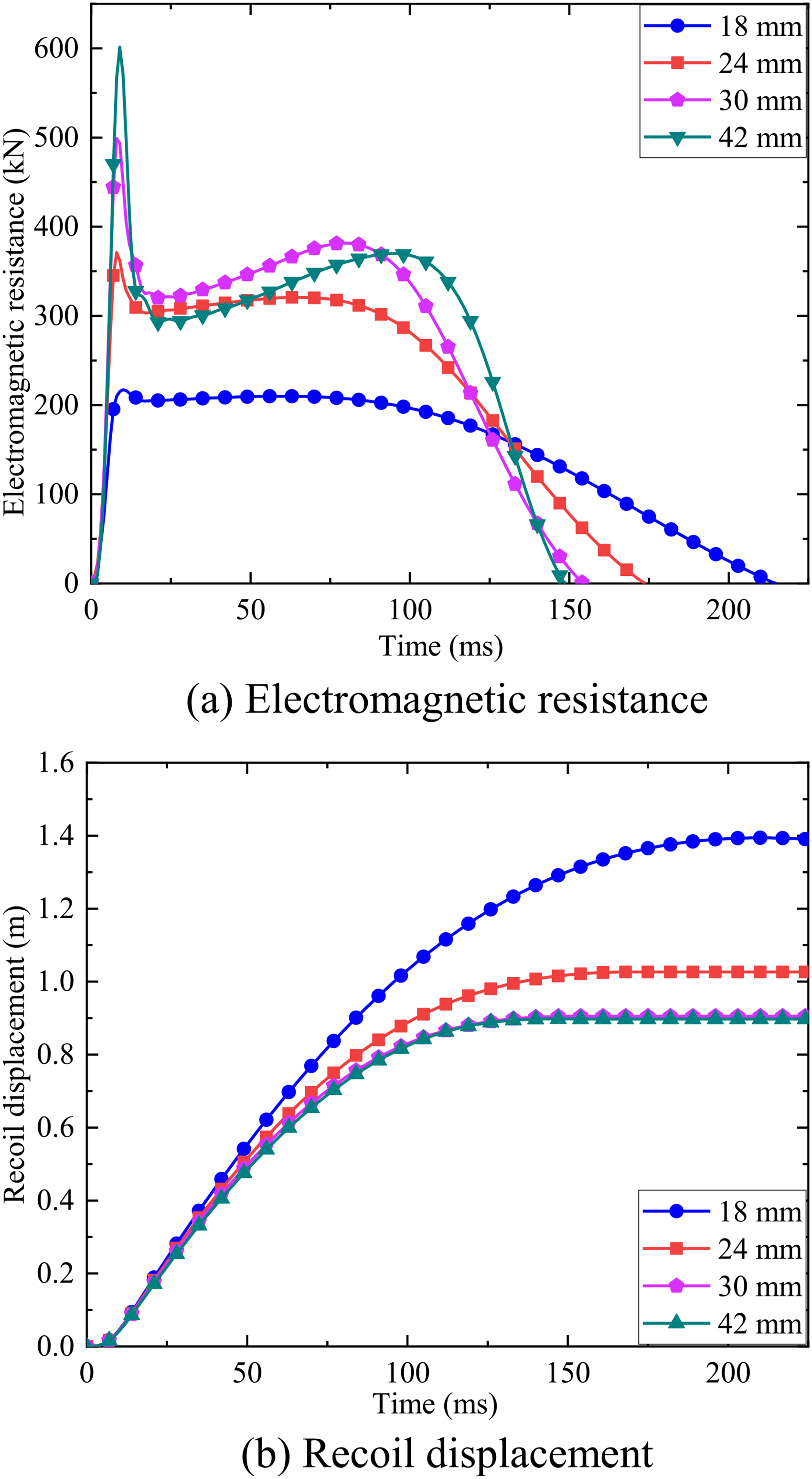
Variation of recoil performance with the pole pitch.
The results for different pole pitches, respectively 18, 24, 30 and 42 mm, are illustrated in Fig. 15. The results indicate that within a certain range, the electromagnetic damping force increases significantly with the increase in pole distance. However, when the pole pitch continues to increase beyond a certain threshold value, although the peak value of the electromagnetic damping force continues to rise, the curve of the electromagnetic damping force and the displacement in the opposite direction (work done by the resistance) remains essentially unchanged.
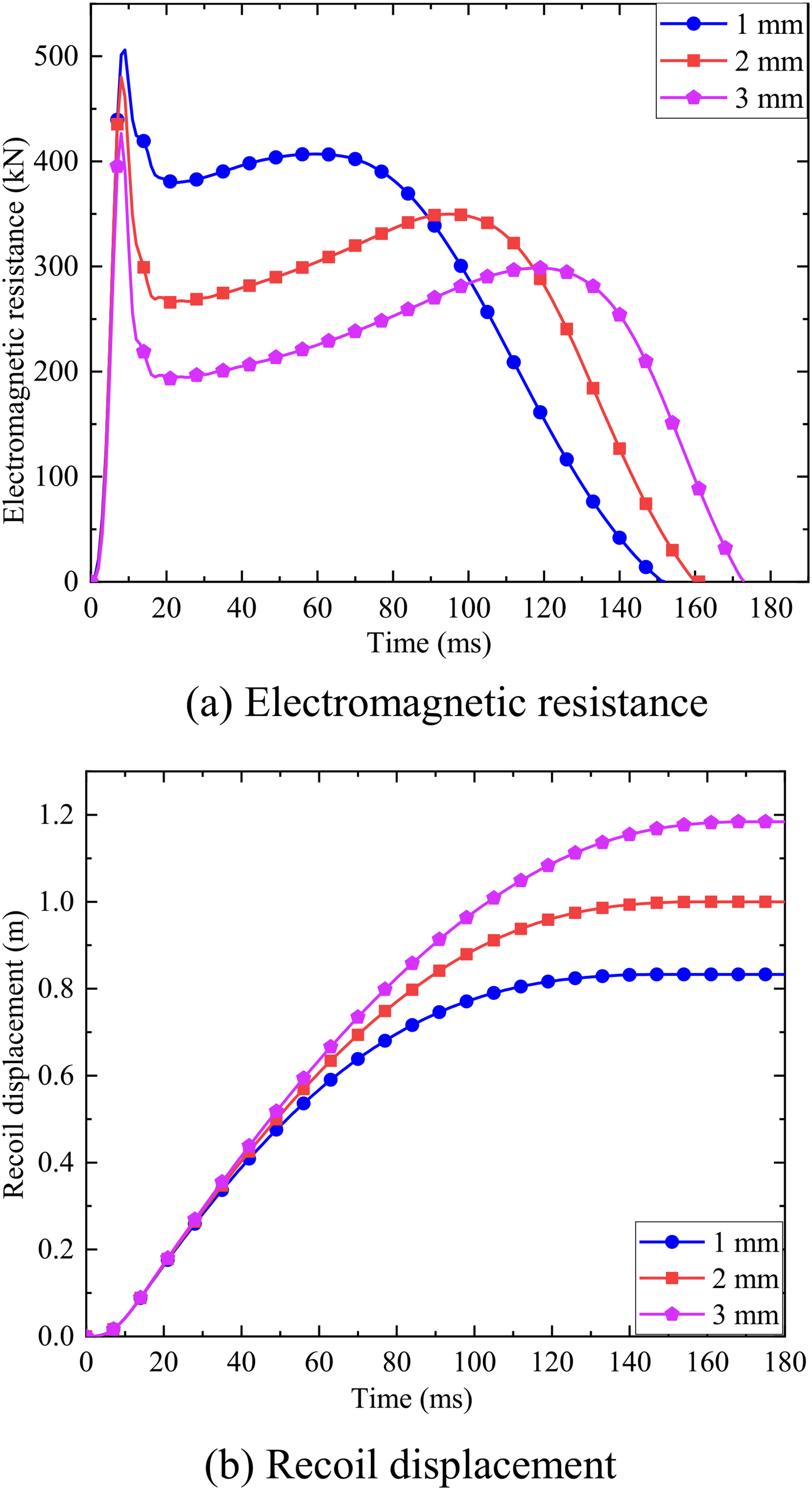
The results for different air gaps, respectively 1, 2, and 3 mm, are illustrated in Fig. 16.

Variation of recoil performance with the air gap.
It is easily obtained that the electromagnetic resistance increases with the decrease of the air gap, as shown by the analytical model and Fig. 16. This is because the magnetic resistance in the air is directly proportional to the distance and is much greater than the magnetic resistance in the conductor. Therefore, when the air gap increases, it leads to a decrease in the magnetic field intensity and electromagnetic damping force at the air gap. Theoretically, the smaller the air gap, the better. However, the chosen size of the air gap in the HE-ECRA is 1 mm, considering factors such as thermal expansion of the metal, heat dissipation, and manufacturing considerations.
The HE-ECRA in this study has a cylindrical structure, where the dimensions of the inner cylinder include thickness and length. The inner cylinder length does not affect the recoil performance, so only the inner cylinder thickness is considered.
Variation of recoil performance with the inner cylinder thickness.
The inner cylinder not only serves as a part of the magnetic circuit but also acts as a medium for generating eddy currents. As the thickness of the inner conductor increases, it has two effects: on one hand, it increases the total magnetic resistance in the magnetic circuit, leading to a decrease in the magnetic field intensity at the air gap; on the other hand, it reduces the electrical resistance of the inner cylinder, resulting in an increase in the amplitude of eddy currents and a more significant demagnetization effect.
The results for different the inner cylinder thickness, respectively 1, 2 and 3 mm, are illustrated in Fig. 17. It is easy to observe that as the thickness of the inner cylinder increases, the electromagnetic damping force decreases, and the recoil displacement increases.
According to Fig. 7, the magnetic source emits magnetic field lines that are guided vertically through the air gap by the magnetic shoe. The appropriate ratio of the axial length of the magnetic source to the magnetic shoe (b:c) can increase the magnetic flux density of the eddy current brake and achieve the goal of low power loss. Similar to the inner cylinder, we only consider the effect of outer cylinder thickness on the HE-ECRA performance.
The results for different ratios with keeping τ = b + c = 30 mm are illustrated in Fig. 18. The explanation in Fig. 18 states that both excessively large and excessively small values of b:c are not beneficial for improving the HE-ECRA performance. Although increasing b will indeed result in more magnetic field lines, the number of magnetic field lines that can be guided and converged by the magnetic shoe will decrease. The excess magnetic field lines are difficult to converge, leading to a loss of magnetic field energy. Conversely, increasing c will lead to a decrease in magnetic field intensity, which is also unfavorable the braking.

Variation of recoil performance with b:c.
Co-simulation modeling
The HE-ECRA can prevent resistance fluctuations caused by phenomena such as armature reaction and magnetic saturation by adjusting the excitation current. Moreover, it enables the adjustment of resistance characteristics, thereby improving the stability of artillery recoil motion. The co-simulation of the HE-ECRA is achieved through the numerical computation software COMSOL and MATLAB /Simulink, and the simulation process is illustrated in Fig. 19.
In the COMSOL, the HE-ECRA structural model is created, and parameters such as material properties, boundary conditions, loads, and magnetic field are set accordingly. The electromagnetic field calculations are performed. In MATLAB/Simulink, the PID controller and fuzzy rules are configured to calculate the excitation current based on the motion state feedback from COMSOL. The resistance is adjusted in real-time by using bidirectional data transmission.
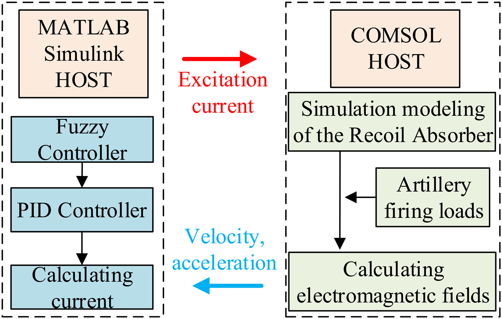
The co-simulation process.
In the design of the fuzzy PID control system for the HE-ECRA, fuzzy rules can be organized based on expert knowledge systems and are presented in Tables 3–5.
For fuzzy system adjustment variables Δk
p
, Δk
i
, Δk
d
, their fuzzy subsets can be defined as {Negative Big (NB), Negative Medium (NM), Negative Small (NS), Zero (ZO), Positive Small (PS), Positive Medium (PM), Positive Big (PB)}. Adjustment variables are determined based on the system error e and its derivative ec. Then,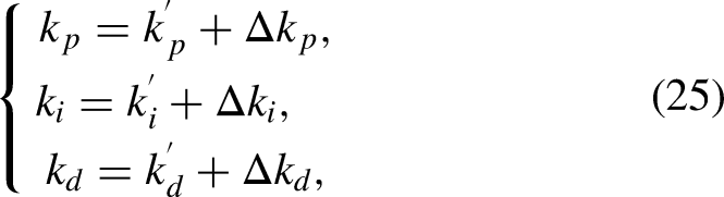
Fuzzy logic table for Δk p
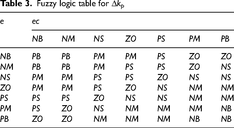
For the proportional coefficient k p , a larger value is chosen in the early stage to improve the response speed of the system, a smaller value is used in the middle stage to reduce the overshoot, and a larger value is chosen in the late stage to reduce the steady-state error.
Fuzzy logic table for Δk i

For the integral coefficient k i , a small value or even zero is chosen in the early stage to avoid the integral saturation phenomenon, a moderate value should be chosen in the middle stage to maintain the stability of the system, and the later stage can be appropriately enlarged to reduce the steady-state error.
Fuzzy logic table for Δk d

For the differential coefficient k d , a larger value should be selected to reduce the overshoot at the beginning of system regulation. It should be appropriately reduced and stabilized during the middle period. In the later period, it should be further reduced to weaken the braking effect of the controlled object.
In summary, a PID controller based on fuzzy inference rules is designed.
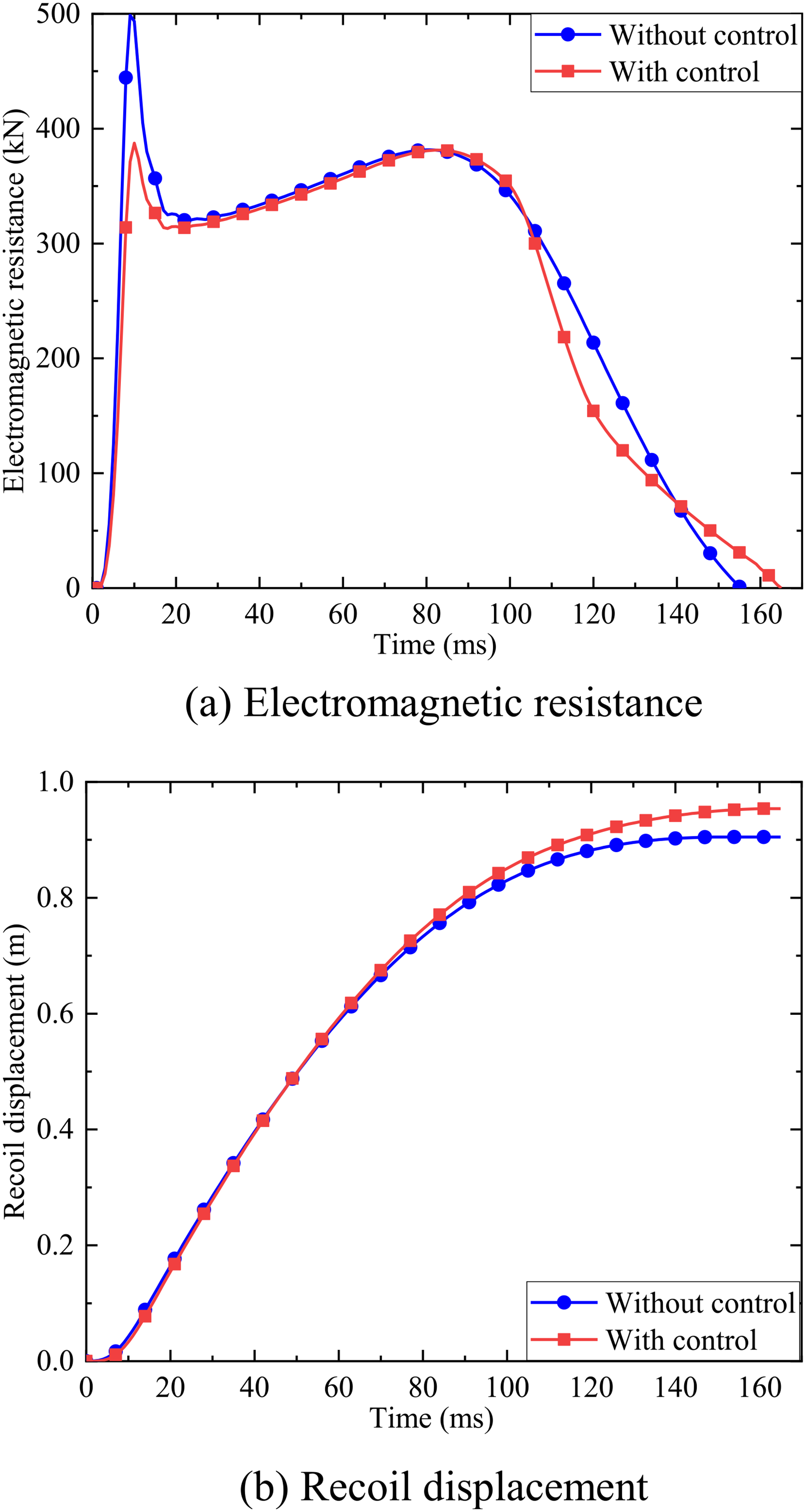
The magnetic field at the air gap can be adjusted by controlling the excitation current, which helps to weaken the ‘saddle’ effect and improve resistance stability. This is a core performance of the hybrid excitation eddy current brake. The cause of the ‘saddle’ effect is detailed in Section 3.
The calculation results are shown in Fig. 20. Figure 20 presents the results of the controlled electromagnetic resistance computed using a finite element model. It is evident that the ‘saddle’ effect is noticeably mitigated, with the peak resistance decreasing from around 500 kN to 370 kN.
Recoil performance with controlled.
Figure 20 compares the recoil displacement, which is a core indicator for measuring the performance of the braking system. It is observed that with the addition of control, the recoil time increased from 157 ms to 165 ms, and the recoil displacement increased from 900 mm to 950 mm, representing a 5.56% increase. Although there is an increase, it still falls within an acceptable range, indicating that the HE-ECRA can achieve the desired performance.
This paper focuses on reducing the impact of instantaneous intensive loads on mechanical structures. Resistance characteristics analysis and control design were conducted for a hybrid excitation eddy current recoil absorber used in large-caliber artillery. The device offers advantages such as a simple structure, controllable resistance, and high reliability. Firstly, the structural design of the HE-ECRA was undertaken. An analytical expression for electromagnetic resistance was derived based on the equivalent subdomain model and validated through finite element analysis methods. Next, a performance analysis was conducted on the HE-ECRA under the intensive impact load environment of artillery firing, discussing the influence of structural parameters on electromagnetic resistance. This provides a theoretical foundation for the subsequent design and optimization of the HE-ECRA. Finally, a control strategy for the HE-ECRA based on fuzzy PID was proposed to mitigate the effects of magnetic saturation and eddy current demagnetization effects on the recoil performance. A co- simulation model was developed to enable bidirectional dynamic data transfer between motion parameters and control parameters. The designed device has effective recoil performance while allowing real-time control of the excitation current, reducing the impact of the ’saddle’ effect, improving energy utilization, and damping force stability. This makes it suitable not only for harsh conditions with instantaneous intensive loads but also for buffering and braking in general mechanical structures.
Footnotes
Acknowledgements
This research was financially supported by the “China National Postdoctoral Program for Innovative Talents” [No. BX20230493], the “Postdoctoral Fellowship Program of CPS” [No. GZB20240979], the ``National Natural Science Foundation of China'' [No. 52305155, No. 52105106], the “Jiangsu Province Natural Science Foundation” [No. BK20230904, No. BK20210342], the “Jiangsu Province Excellent Postdoctoral Program” [No. 2023ZB318].