
Abstract
The internal parameters is one of the important calibration parameters of visual measurement, which shows the accurate corresponding relation of the space point and the imaging point in computer image coordinate. Based on fiber optic imaging characteristics, the paper proposed the circular array targets and sub-pixel threshold segmentation algorithm to extract target feature points as to help the follow-up the accurate calibration of camera internal parameters. In contrast to some commonly uesd algorithm to extract the sub-pixel edge contour using interpolation and fitting, the proposed sub-pixel threshold segment algorithm is more small computational complexity and execution time. The experimental results show that the camera internal parameters have been obtained precisely with low execution time, which provides important guarantee for subsequent fiber length measurement based on visual measurement.
Keywords
Introduction
Fiber coil is a sensitive component of Fiber Optic Gyro used to provide the light path generating the Sagnac effect. The fiber coil is comprised of several hundred meters or several kilometers of fiber optic. From Sagnac effect and the basic principle of interferometric fiber optic gyroscope, the phase difference caused by time difference between two beams light propagating in fiber coil is proportional to the average diameter and winding length of fiber coil [1]. We know that the longer fiber coil winding length, the greater the average diameter, the higher the sensitivity of the FOG. According to the different application, the sensitivity of the FOG can be changed by changing the fiber coil winding length.
In general, the diameter of fiber optical used as sensing coil is 125
Traditional calibration requires some expensive apparatus,which is gradually eliminated [4]. Self-calibration. The method does not use any calibration object. It uses the constraints on the cameras’ internal parameters to solve internal and external parameters of camera imaging model. Self-calibration method is suitable to some special circumstance where do not place calibration target. But many parameters need to be estimated, so the method is used rarely [5]. Planar-object-based calibration. The method uses a planar calibration pattern that provides mark points with good precision. The camera is fixed and take pictures of the pattern placed at several different orientations. The method was proposed by Zhang zhengyou first. In the paper, zhang uses the squares array as the calibration pattern and uses the corners of squares as the mark points. Intelligent-algorithm-based calibration. The method applies some intelligent algorithm on camera calibration. Bouchouicha et al. [6] apply genetic algorithm on calibrating non-linear model. The calibration method is suitable to solve those problems which are difficulty to establish assured mathematical model or no-formal model and can correct nonlinear distortion of camera. But the disadvantage of the calibration method is huge computation.
The remainder of this paper is structured as follows. Section 2 includes some analysis on camera model. In Section 3, we give a calibration pattern and feature extraction algorithm precisely. Section 6 shows the experimental facility and results. Conclusions are drawn in Section 5.
The principle of vision measurement is the use of the detected object images captured to calculate the geometry of the object in three-dimensional. In the process of vision measurement, the camera model is used to build the mathematical relation of the point between world coordinate and camera coordinate. Ideal imaging model is central projection imaging model which is linear model of imaging relationship. In practice, the non-linear factors need to be added in linear model to describe accurately the imaging process.
The linear model
In practice, camera can be placed anywhere in which the target image can be captured. In the workplace, we can choose a reference coordinate system to describe the location of the camera and any other objects. Figure 1 illustrates how a camera projects a 3D world point
The projection model.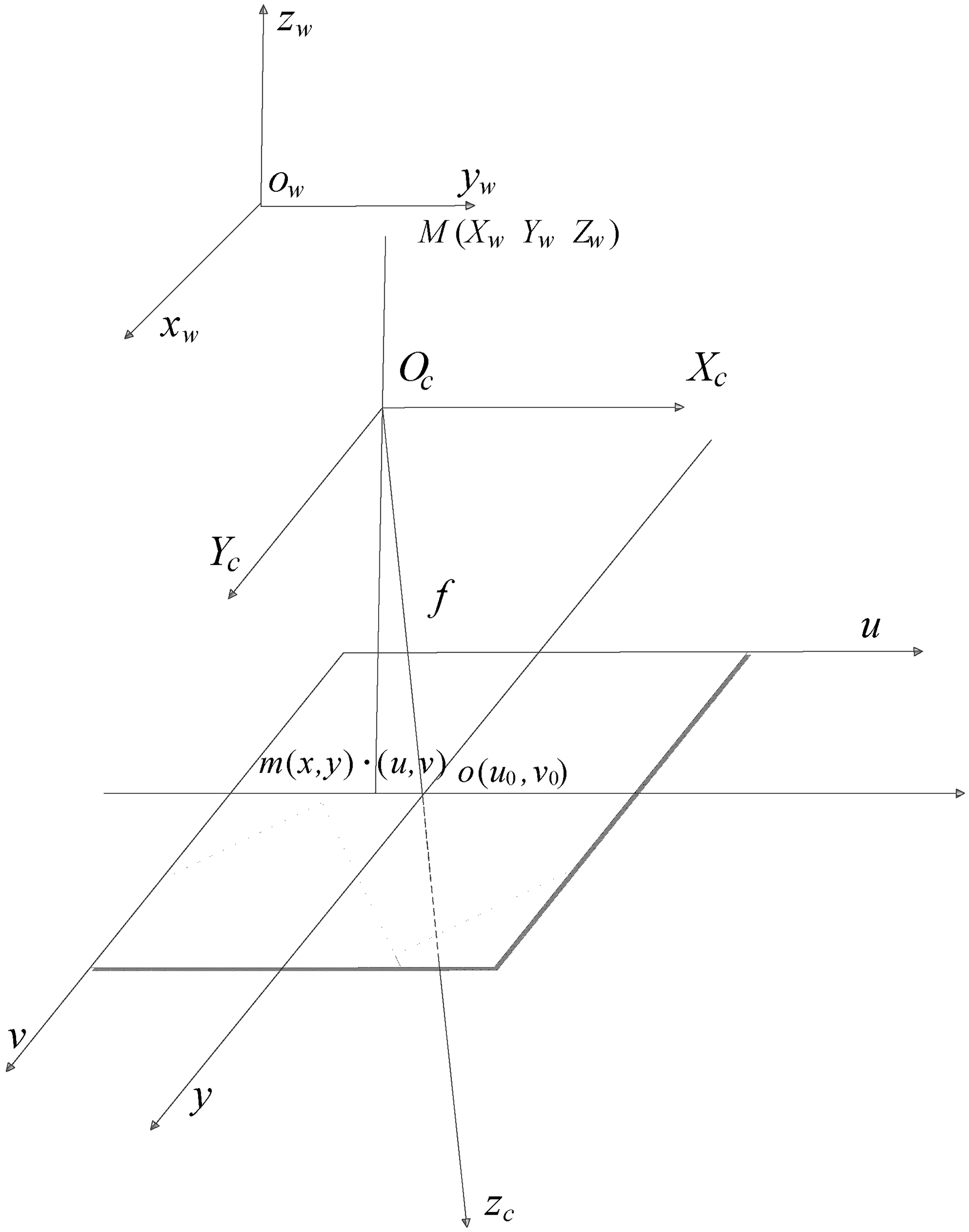
The transformation relation of world coordinate system and camera coordinate system can be built by rotation matrix
Where,
From Fig. 1 and the principle of central projection imaging, the relation of camera coordinate and image coordinate can be described as Eq. (2) in homogeneous form.
Where,
The image coordinate and the pixel coordinate of 2D point
Where, dx, dy is respectively the physical dimensions of pixel in
According to the relation of Eqs (1)–(3), the camera can be modeled linearly by Eq. (4).
Where, the matrix
Planar target point
Where, homo-graphic matrix
The Eq. (6) shows that each pair of calibration feature points and its image point can provide two linear equations about the homographic matrix, which can be shown as Eq. (7).
Take at least four groups on the planar target points can build eight linear equation, we can obtain the homographic matrix.
Fundamentally, the radial, tangential and thin prism distortions exist in every camera lens [7]. Owing to distortion errors, the image coordinate of 3D point is not located at
Where,
The primary distortion is radial distortion which is caused by imperfect lens shape. In general, the other distortions are ignoerd because of the smaller influence to the result [8]. In practice, the radial distortion is enough to describe the non-linear distortion. Radial distortion can be expressed as Eq. (9).
Where,
From Eq. (5), the relative quantity of distortion (
In the case of considering the lens distortions, the coefficient of non-linear distortion
Calibration pattern
In practice, in order to improve the accuracy of industrial vision measurement system, the calibration feature point in calibration pattern should be considered that their shape and the scope is as close to the shape and the scope of detected object as possible. According to the imaging feature of fiber, the calibration pattern we use is a planar circular array board. We take the center point of every circular in calibration pattern as calibration feature point. In order to obtain the accurate coordinate of calibration feature points in world coordinate system, we build the world coordinate system shown in Fig. 2.
Planar circular array board and its coordinate system.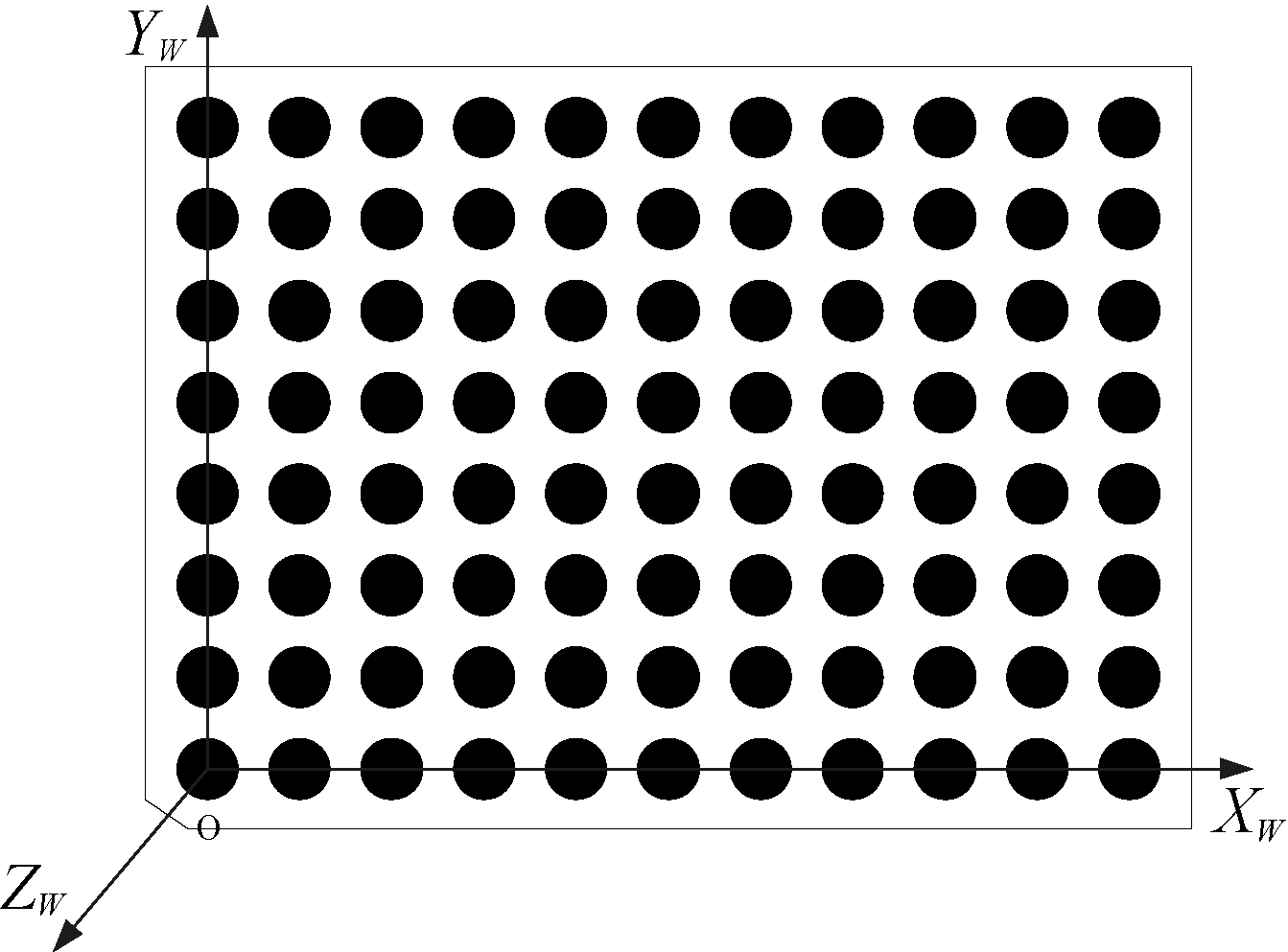
In the coordinate system, the coordinate of all calibration feature point in the world system is known. We take multiple images of the calibration pattern along different orientations by a fixed camera as raw data to calibrate camera. These images were shown in Fig. 3.
The planar circular array board in the different position.
Image analysis and processing of visual measurement is a complicated process, which need reduce the complexity of the algorithm and the amount of calculation to simultaneously meet the requirements of high reliability, high precision and real-time performance [9]. In view of the poor positioning accuracy of pixel edge detection algorithm and the great computational complexity of subpixel edge detection algorithm, the paper put forward the subpixel accuracy threshold segmentation algorithm and least square ellipse fitting method to accurately calculate the circular array calibration feature points of targets.
When the obvious gray difference occur between interest areas in the image and the background, we can set the appropriate threshold for segmentation pixel object edge [10]. Sub-pixel level edge can be successively formed from the horizontal and vertical directions by the linear interpolation. So sub-pixel threshold segmentation can be obtained by the intersection of the constants function
The Eqs (12) and (13) can be obtained by the horizontal linear interpolation.
Where,
The Eq. (14) can be obtained by the vertical linear interpolation.
With Eqs (12)–(14) get the gray value of the interpolation points
The Eq. (15) can be shown with matrix as following Eq. (16).
Obviously, the weight of the four pixels
We establish visual measuring system to verify the proposed algorithm by which, we verified that target location accuracy and the execution time of sub-pixel threshold segmentation algorithm and the other sub-pixel edge detection algorithms based on Sobel and Canny operator in extraction of elliptic contour precision. The results shows subpixel threshold segmentation algorithm in feature points calibration is accuracy and rapid.
The apparatus and experiments
The experimental equipment include the following parts: the industrial digital CCD camera with 1292
From Fig. 4, we use the least squares ellipse to fit ellipse center (shown in Fig. 4b) according to the contour of circular array targets (shown in Fig. 4a). The standard deviation of position accuracy among the three algorithms is shown in Table 1. At the same time, the enlarge figure of edge contour (shown in Fig. 4c) can show the difference of three algorithms. The accuracy of the proposed algorithm is directly affected by the threshold. The threshold can be selected according to the histogram of the image. Because the fiber image has obvious gray difference between object and background, so the histogram will have two distinct peaks. The threshold is the minimum value between the object and background. But usually, due to the minimum value is not particularly evident, we need smooth histogram with Gauss filtering function, then find the two peaks. The minimum value between two peaks can be shown in Fig. 4d. We can get threshold
The standard deviation of part center coordinates
The standard deviation of part center coordinates
The algorithm validation and gray histogram.
Under the same experimental environment, we select 5 target images in the same position seen in Fig. 3 and take advantage of the proposed algorithm to calculate the center coordinates and the corresponding standard deviation, the results are shown in Table 2.
The center coordinates and standard deviation in
According to the standard deviation of three algorithm (sub-pixel algorithm based on canny operater, sub-pixel algorithm based on sobel operater and the proposed algorithm with
For rapidity of three algorithm, we use the “cputime” in Matlab to calculate the execution time. These algorithms is executed by Intel Core i3-3240 CPU, running at 3.2 GHZ with 2 GB RAM under win 7. The propossed images of 1245
The execution time of three algorithm extracting edge contour
The execution time of three algorithm extracting edge contour
From Table 3, we can see that the execution time of proposed algorithm is the shortest. So, we verify the performance of proposed algorithm is optimal. Through the feature point coordinate in world coordinate system and extracted feature points in target images (see Table 2), we obtained ellipse center coordinates. According to the Eqs (8) and (9), the homo-graphic matrix is obtained and the homo-graphic matrix is optimized by the nonlinear optimization algorithm, then the camera internal parameters can be calculated and their standard deviations are shown in Table 4.
The camera internal parameters with distortion
The camera internal parameters and the standard deviations are shown in Table 4. The results are obtained taking one of the most close to the average calibration results using the calibration five picture. From Table 4, we can verify the stability of the calibration algorithm.
The camera parameters calibration is an important process of visual measurement. However, the camera calibration method is different with different measured targets. Therefore, the novelty and contribution in this work is a rapid and computationally effective sub-pixel threshold segmentation algorithm and circular array targets with low errors for fiber length measurement based on vision. The proposed algorithm is used to extract the planar circular array images. The expenrimental results can show that the sub-pixel threshold segment is optimal in the accuracy and rapidity of extracting feature point comparing with the other two classical aigorithm such as sub-pixel canny opertor and sub-pixel sobel opertor. Its practical advantages was proved by these data shown in Tables 1 and 2, the low computational time also was proved by the data shown in Table 3.
The most significant drawback of the proposed algorithm is that it can handle only the images with obvious gray level difference between region of interest and the background. On the other hand, when the image is not clear, the selected threshold will produce very big effect to outline the edge of the planar circular array. we should pay attention that each algorithm has its applicable range and the most suitable applications.
The usability and high performance of the proposed technique for the camera internal parameters calibration is demonstrated by the obtained results from experiment. The proposed algorithm can also be used for non-contact measurement process of flexible material. In engineering applications, we should collect consider the influence of main shaft beating degrees for visual measurement in the later research we will complete this part.
Footnotes
Acknowledgments
This work was supports in part by the Shanxi province foundation for science and technology research (2015021104) and science and technology research projects (2015031007-1) and the research foundation in NUC.