



Abstract
With the continuous research and development of remote sensing, it has become the consensus of the industry that spectral and polarization remote sensing can provide more information than ordinary imagery. In particular, it has obvious advantages in the analysis of the changes in “water bodies”, “gases” and “vegetation”, it also can be used for more accurate detection and analysis, so it is increasingly used in remote sensing and military investigations. Based on the study of polarization imaging mechanism, this paper proposes a single polarizer time-lapse imaging method to acquire polarization images, we complete the control of polarization imaging and polarization image processing using LabVIEW, achieve polarization information fusion, and finally improve the contrast between the target and the background.
Introduction
According to the electromagnetic theory of light waves, the main characteristics of light waves are: light intensity, wavelength, phase and polarization state. Optical radiation imaging is used to acquire the image by acquiring the light wave characteristics of the target and inverting the target nature parameters. Among them, the polarization property is closely related to the material properties and is the main information parameter to be acquired by remote sensing. In the optical band, whether it is visible light or other spectral bands, different targets have their own respective polarization characteristics. In recent years, the use of this feature to obtain the measured target information, and then the polarization imaging research has become a hot spot.
Polarization imaging has passive work and active work [9]. Passive work has the advantages of good covertness, but the imaging effect and distance are subject to meteorological conditions, the target temperature contrast, sky background illumination and other factors. Active work uses the laser illumination polarization imaging technology. Relative to passive imaging, this technique relies on emitted laser light as a source of illumination, independent of the target’s own radiation and target’s reflection of secondary light sources such as the sun or the moon. Extracting target information by reflecting or scattering photons from the detected target. It overcomes the shortcomings of passive imaging and is not affected by meteorological conditions, target temperature and background illumination. It has wide application prospects into long-distance dark target detection, underwater detection, remote sensing and military target recognition [9].
After years of development, both passive and active working methods based on imaging sensors and working principle of polarization imaging can be broadly divided into five categories [13]: (1) Mechanical rotating polarization optics imaging technology; (2) Sub-amplitude polarization imaging technology; (3) Liquid crystal tunable filter polarization imaging technology; (4) Sub-aperture polarization imaging; (5) Focal plane and channel modulation polarization imaging technology.
In this paper, using a virtual instrument development platform, a rotating polarization polarimetric polarization imaging system for passive imaging of polarization imaging is designed and fabricated. The sensor uses a mechanically rotating polarizer to project the polarization state of the measured target’s information to the CCD camera. The computer uses the computer to combine the polarization image with the extracted image Stokes parameters to mine the polarization information of the image and provide more dimensional goals. Information eventually reaches the goal of improving the detection and identification capabilities of photodetection equipment.
Polarization imaging basic principle
The light wave is a transverse wave, its electric vector vibration plane and the propagation direction perpendicular to each other, the electric field vibration direction relative to the propagation direction asymmetry is called polarization, the polarization of light can be defined by the polarization degree
Define the degree of polarization,
In the field of optical polarization remote sensing, Stokes vector method is usually used to express the polarization state of light [7]:
Degree of polarization is
Polarization azimuth angle is
In the formula,
When the beam interacts with the material, the four Stokes parameters of the outgoing beam are linearly related to the four Stokes parameters of the incident beam. Writing in matrix form is
Considering that the Stokes parameter is a quaternion vector, at least four equations are needed to solve for the complete Stokes parameter of a target point to be measured. When incident light passes through an ideal polarizer, the Miller matrix of an ideal polarizer that forms a p-angle with the reference direction is
The Stokes parameter
The intensity of transmitted light can be derived as
In this way, three independent equations can be obtained in 0
Light polarization state is divided into non-polarization, circular polarization, linear polarization, partial polarization and elliptical polarization [15]. In order to reverse the multi-angle polarization reflection by using two-way reflection, the polarization state and the light intensity of these five polarization states after passing through the polarizer can be obtained. According to Marius’s law, the intensity of two polarized light through the analyzer, the transmitted light intensity is
Among them,
A typical polarization imaging system consists of a rotating polarizer (mechanical rotating polarizer), an optical lens, a CCD camera and a polarization analyzer, as shown in Fig. 1. According to different polarization methods, the polarization imaging system can be divided into time-sharing polarization imaging system and synchronous polarization imaging system [11], this article uses the time-sharing polarization imaging system.
Polarization imaging principle.
The polarizer is a film made by artificial method, and special selective crystal particles with strong selective absorption are regularly arranged in the transparent adhesive layer, which allows the light transmitted through the polarization direction to absorb the light with its vertical vibration, and has dichroism. Therefore, after the natural light passes through the polarizer, the transmitted light becomes substantially plane polarized light. Obtaining an angle image requires the use of a polarizer. As the rotating polarizer adopts a mechanical rotating structure, the stepping motor is used to control the rotating angle of the deflector. Polarization analyzer takes advantage of the software methods to analyze and process the image information collected by CCD camera. Imaging circuit block diagram shown in Fig. 2.
Polarization imaging circuit block diagram.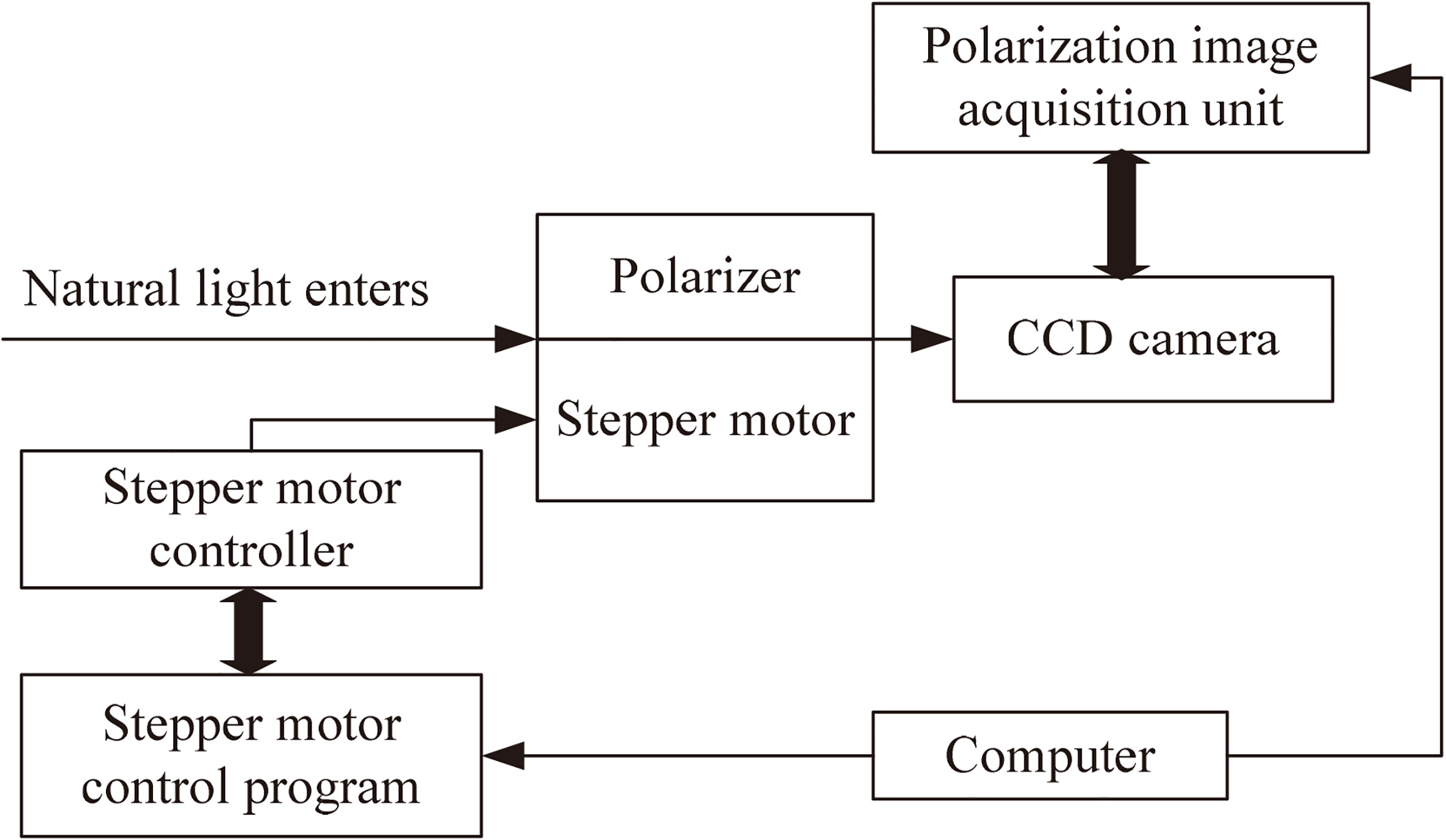
The measurement of light polarization can be done with the Stokes parameter, measurement accuracy depends on the space and time resolution of the measurement. According to the response speed of the detection system, the polarization analysis methods are mainly divided into two categories: one is the polarization modulation method, the introduction of the polarizer and the phase retarder in the optical path to be measured; the other is the sub-amplitude, sub-aperture or sub- Focal plane imaging method.
System calibration method
Calibration is the use of the known parameters of the polarized light measurements to obtain the matrix of the instrument. Each working wavelength need only be calibrated once, and after calibration the instrument matrix will be stored for later use in the measurement of the polarization state. The system will be placed in the standard state of polarization measuring instrument at the CCD camera at a rotational angle control of the rotating polarizer horizontal, vertical, 45
Rotary polarizer control
In this paper, the rotating polarizer is PRM1/MZ8 rotating polarizer manufactured by THORLABS company, as shown in Fig. 3.
Rotary polarizer.
The rotating polarizer is controlled by a stepping motor. The principle and procedure of the stepping motor control are shown in Fig. 4.
Stepper motor control block diagram.
Polarization imaging system software design
In this paper, the final PC platform is built by designing the program based on LabVIEW platform for image acquisition, Stokes image calculation, polarization image preprocessing and image fusion. LabVIEW is a virtual instrument simulation application with multiple functions. LabVIEW uses a graphical editing G language program, and the resulting program is in the form of a block diagram. LabVIEW has a wealth of library functions for signal processing, real-time control, and data acquisition. Based on the above characteristics of LabVIEW, it is used to write software to realize the driving control of the rotating polarizer, subsequent image acquisition and image processing.
Polarimetric imaging system software block diagram is shown in Fig. 5, which divided into four parts: image acquisition, image preprocessing, polarization image computing (Stokes parameter extraction) and image fusion.
Polarization image acquisition system design block diagram.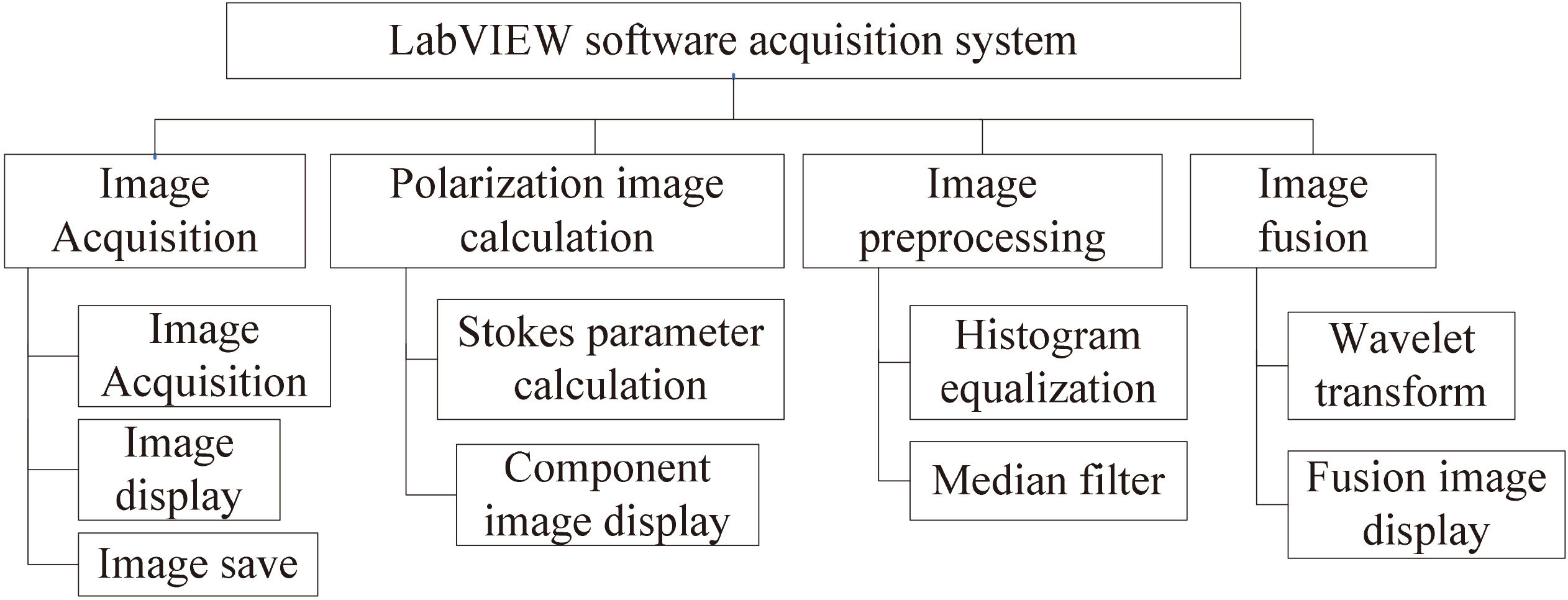
The image acquisition is the first step in the entire system. It is mainly to make the image of polarized light which contains measured polarization information on the CCD camera by adjusting the rotating polarizer and the Stokes parameters at 0
Get S0 image flow chart.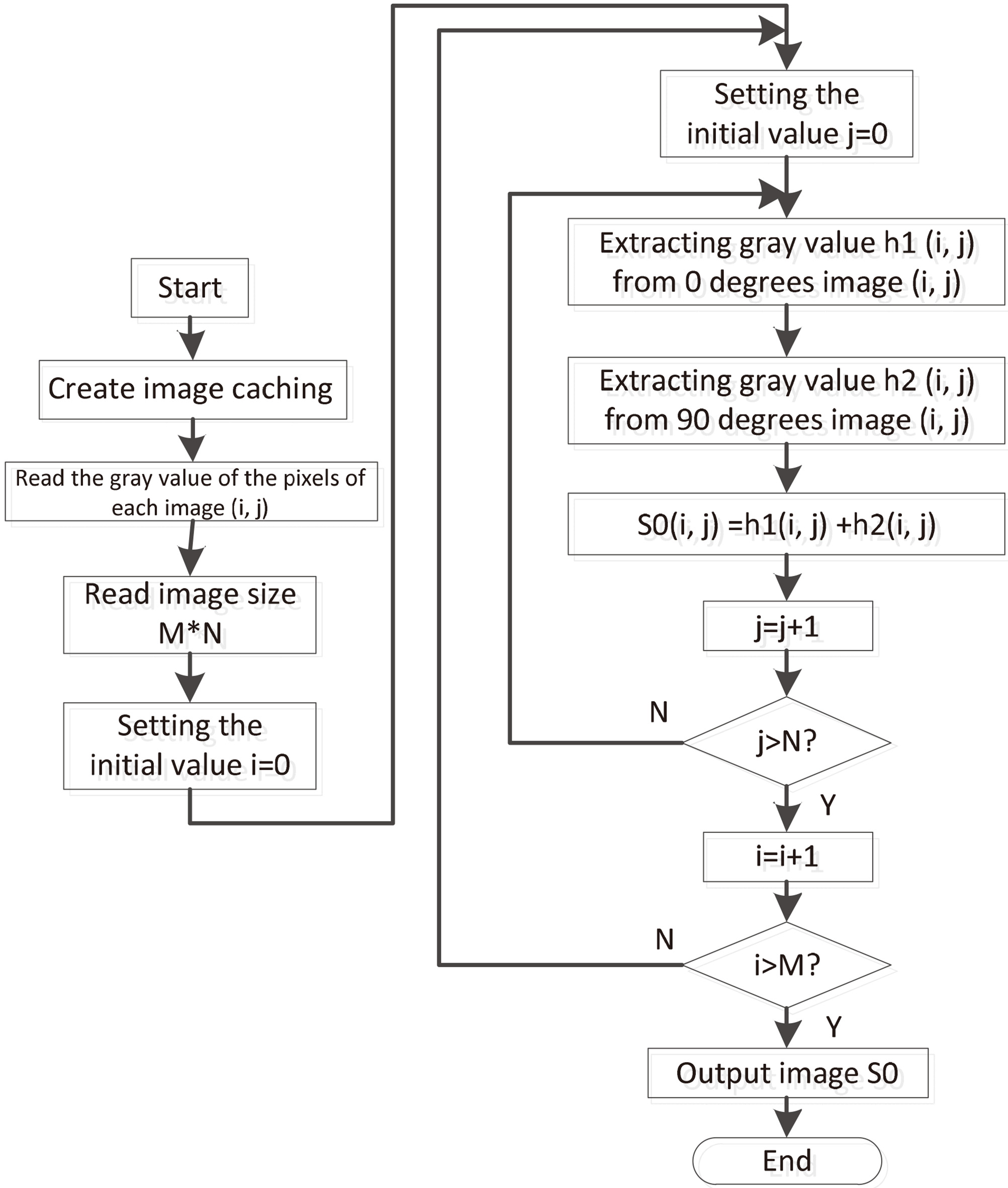
The polarization degree image DOLP and the polarization angle image AOP are obtained by calculation. Polarization parameter images are mainly based on the Eqs (6)–(8) derived Stokes vector four parameters of the calculation equation, through the joint solution can be calculated S0, S1, S2, and then get the polarization image and polarization angle of the image.
Taking the S0 image as an example, the process of obtaining S0, S1 and S2 images is illustrated. The S0 image is obtained by adding the 0
This article uses the corner of the laboratory as a scenario and experimented with the LabVIEW platform, the results are shown in Fig. 7. S0, S1, S2, DOLP and AOP images are obtained after the images are acquired, where S1 and S2 contain the more abundant polarization information in the target object. DOLP and AOP are more obvious description of the target contour. Using the results obtained, the next step based on wavelet transform image fusion.
Polarization image display.
Compared with traditional optical imaging, polarized target imaging can provide more information about the surface roughness, texture, physical and chemical properties of materials, but it is easy to lose the details of the image information and does not fully reflect the polarization information of the target reflected light. By using information redundancy and complementarity between polarized images, the obtained image polarization information and intensity information are fused to enhance the contrast of the image and improve the original target information.
Firstly, obtain the P image though fusion the polarization degree image and the polarization angle image, then fusion polarization information. Secondly, the P image and the S0 image are read for wavelet transformation, then fusion the polarization information and the intensity information. Figure 8a and b are the flow charts of P image and wavelet transform respectively.
(a) Find P image flow chart; (b) Find Y image flow chart.
The actual effect after fusion is shown in Fig. 9, and the P image is compared with the S0 image as shown in Fig. 10. The S0 image contains intensity information, the P image contains polarization information, and the Y image is a fused image. The result shows that the details of the image are presented.
Wavelet transform fusion image display.
S0 image, polarization fusion image and wavelet transform image display.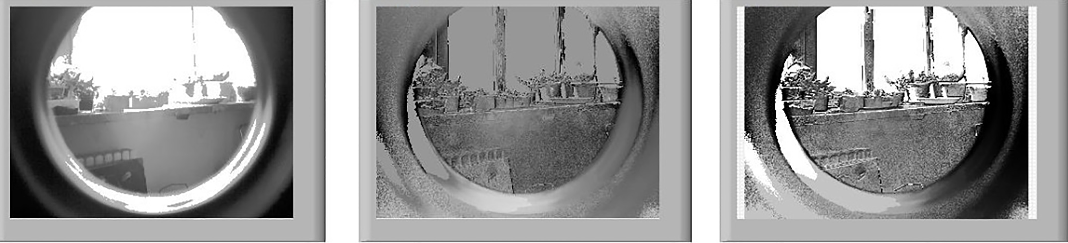
To measure the quality of fused images, qualitative and quantitative analysis must be performed to determine whether they meet the requirements or reflect the merits of the algorithm. For the experimental results in this paper, subjective and objective analysis methods are used respectively. The subjective evaluation method is simple and intuitive, relying solely on human visual characteristics to quickly evaluate the quality of the image. The disadvantage is that the method is one-sided, has a strong subjectivity and uncertainty, and cannot stand repeated inspections, when the difference between the fusion images are not obvious or the observation object and the objective environment change, subjective evaluation methods are not given to make an accurate judgment. Therefore, a set of objective quality evaluation criteria is needed. In practice, we often use a combination of subjective and objective evaluation methods for quality assessment.
For the subjective analysis, as shown in Fig. 10, the serious reflective window frame and the flowerpot in the original image can be clearly observed, and after the image processing, the detail information is obviously increased, and the outline and the window frame of the flowerpot are presented, achieve the desired effect. In the objective analysis method, the standard deviation, gradient value and entropy of the original image and the fused image are calculated respectively. Specific calculation of indicators as shown in Table 1.
Fusion evaluation index
As can be seen from Table 1, the standard deviation of the fused image is significantly higher than the standard deviation of the original image, indicating that the gray level of the image is dispersed and the contrast of the image is improved. After fusion, the gradient value of the image is also higher than that of the original image, indicating that the image has more layers and the contrast and texture details also increase. The entropy of the fused image is higher than that of the original image, which indicates that the fused image contains more information. Based on the above subjective analysis and objective analysis, it is shown that the contrast effect of the fused image is better than the original image.
Based on LabVIEW platform, we design and fabricate a polarization automatic imaging system for the rotating polarizer. By analyzing the detailed information in the S0 image and the edge information in the DOLP and AOP images, a multi-resolution wavelet fusion algorithm based on polarization parameters is proposed, and the background information is weakened by using a combination of polarization imaging and intensity image processing techniques. The numerical values of DOLP and AOP correspond to the intensity space. Experimental results show that the algorithm greatly weakens the background component information, improves the clarity of the target image contour, achieve the improvement of the target background contrast.