
Abstract
A design of Ethernet adapter for visible light communication (VLC) is proposed in this paper. Based on field-programmable gate array (FPGA) technology and Ethernet protocols, the design applies Ethernet to VLC channel, enabling two-way transmission between both channels, giving solution to the conversion of signal between different coding formats. 8B10B DC-balanced encoding/decoding is used for VLC transceivers to ensure reliable and stable communication. At 1000BASE-T duplex mode, the maximum real-time net data rate on the VLC channel is 300Mbps by sending and receiving Ethernet frames in point-to-point communication with optical transceivers using phosphorescent white light emitting diode (WLED).
Introduction
Visible light communication (VLC) has developed rapidly in recent years. It has a wide range of usable spectrum, good confidentiality, and also an eco-friendly feature. VLC can work as a supplement of current wireless communication, and can be merged with the Internet of Things [1]. White light emitting diodes (WLEDs) can be modulated with high data rate data, when they are lighting at the same time [2]. In order to pursue high speed VLC application, Gigabit Ethernet is a proper choice as a way of communication running on VLC channel, and study on Ethernet-VLC communication using commercial phosphorescent WLED [3] is worth attention.
The proposed design in this paper is an Ethernet adapter which acts as a relay connecting Ethernet to VLC channel which uses on-off keying (OOK) modulation. In VLC situation, OOK means using visible light as the carrier and modulating it with 0 s and 1 s. The adapter can also be a testbed for VLC transceivers. The main function of the design is conversion of coding format, which is the key to data transmission. For Gigabit Ethernet, the coding format is 4D-PAM5 while the VLC transceiver uses binary code. The adapter is implemented using intelFPGA (EP4CE10) for core function, with an Ethernet transceiver for Ethernet Physical Layer, and serial transceiver chips interfacing VLC transceivers, whose transmitter module converts serial electronic signal to optical signal and receiver module converts the received optical signal back to serial electronic signal. The function of the FPGA core logic is proven by board-level test, and the function of the adapter is also proven by experiment. Test results show that at 1000BASE-T duplex mode, the proposed adapter design supports maximum real-time net data rate of 300 Mbps on sending Ethernet frames when the line rate (with coding redundancy) of the VLC channel is 450 Mbps. The adapter system can be used in actual application systems where VLC is used. The research work will promote the application of high-speed VLC system used in different situations.
Board-level support for the design
The adapter design is mainly made up of three parts: the interface between FPGA and Ethernet transceiver, the interface between FPGA and external serial transceivers, and the core function implemented in FPGA. The interface between Ethernet and FPGA is gigabit media-independent interface (GMII) which is a form of reconciliation sub-layer (RS) described in IEEE 802.3 Ethernet standard. Based on SERializer-DESerializer (SERDES) technology, we use SN65LV1023/1224 (Texas Instruments) for serial transceivers in this design. The deserializer has built-in clock and data recovery (CDR) logic which recovers data and its sampling clock from the serial input, and does not need reference clock from the data source, which suits the situation that VLC transceivers do not spare another channel for sampling clock. In addition, the deserializer has a “loss-of-lock” output port in order to provide real-time lock status of the recovered clock. 8B10B encoding/decoding is used onto VLC channel. It maps every 8-bit data onto the corresponding 10-bit word and ensures DC-balance during serial transmission. Such encoding feature confines the number of running 0 s or 1 s to the maximum of 5, and maintains relatively stable transmission on VLC channel using OOK modulation [4].
The reason of using external transceiver chips instead of transceiver-integrated FPGAs is that FPGAs with integrated transceivers do not support line rate below 600 Mbps [5] or 500 Mbps [6], while the target data rate is 300 Mbps. It is decided by the performance of WLED-based VLC transceiver. Another reason is that such strategy frees FPGA from implementing SERDES logic within itself and betters the FPGA performance on implementing core function. The transceiver ASIC uses a ten-bit interface and its data pattern is shown in Fig. 1. With a start bit and a stop bit inserted between data words, the actual line rate is 450 Mbps on the serial channel when the net data rate is 300 Mbps.
Data pattern of the SN65LVxxxx transceiver.
The block diagram of a single adapter is described in Fig. 2 (In Fig. 2, “ser” is short for “serializer”, “des” is short for “deserializer”, “buf” is short for “buffer”, “if” is short for “interface”, “Eth” is short for Ethernet, “Eth PHY” is short for Ethernet Physical Layer, and “Eth MAC” is short for Ethernet Media Access Control Layer).
Simplified block diagram of a single adapter system.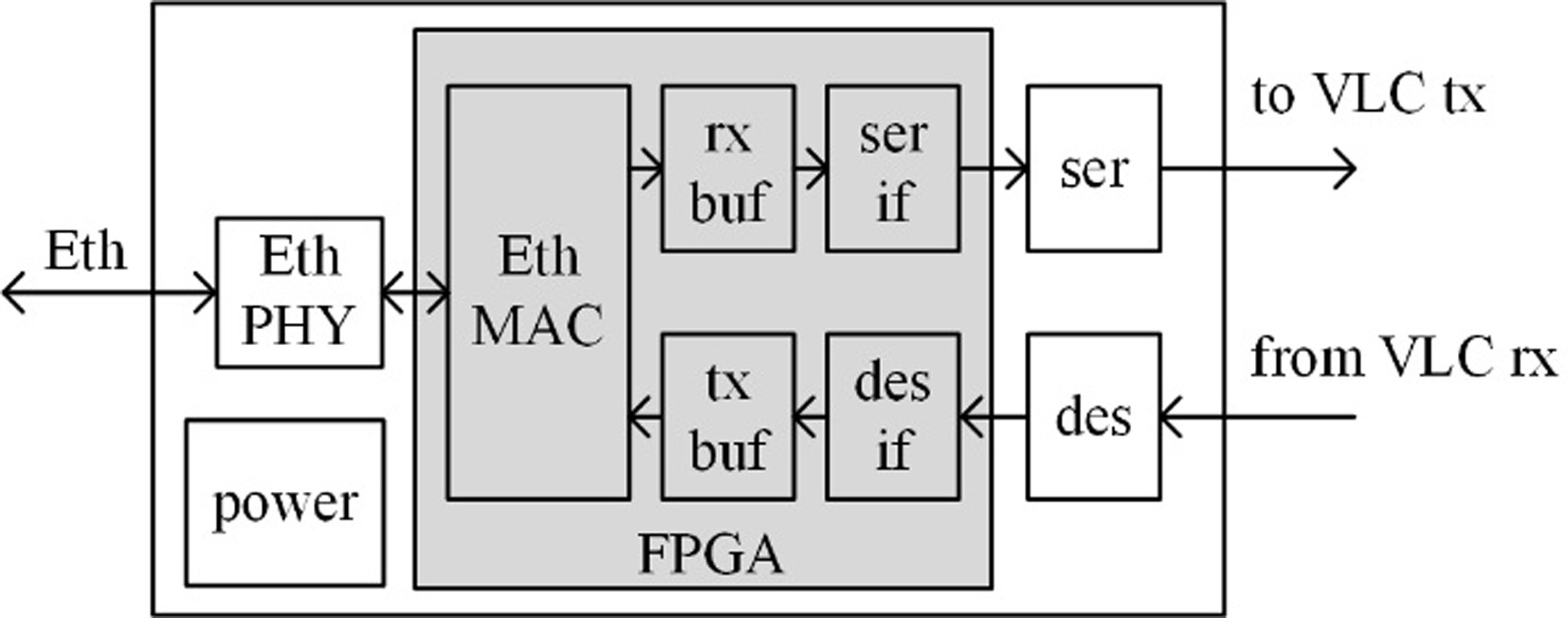
Figure 3 demonstrates an example of point-to-point communication using a pair of adapters, in which “eth” stands for the adapter, and “vlc” stands for VLC transceivers. Details of each function are described in the following sections.
Simplified block diagram of point-to-point communication system.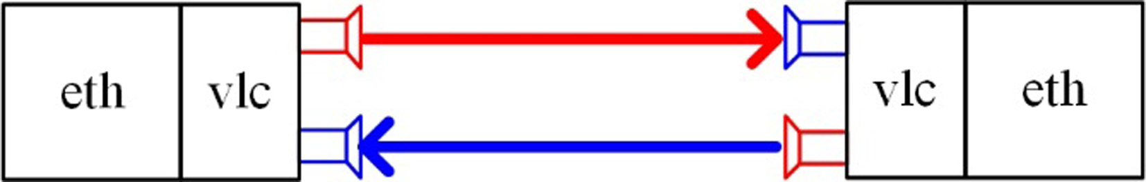
When an Ethernet frame is processed through RS, it enters MAC layer for further processing. Here in the design, the main function of MAC layer is to identify valid received Ethernet frames and discard fragments, and to encapsulate the frames to send with headers.
Frame encapsulation and encoding at VLC side is done by the transmitting logic, in which the encoded data stream is sent to the external serializer from FPGA for serialization. The receiving logic at VLC side recovers the received data by de-serializing the serial input and sending the parallel data into FPGA, decoding the de-serialized data stream to frames, and de-encapsulating the received frames. It also monitors the link status of VLC channel in order to indicate whether the optic link is calibrated. The 8B10B encoding/decoding block is used in which the frame is coded with data words, and the inter-frame gap (IFG) is coded with control words [7]. Such rule enables that the receiving logic gets valid data between IFGs.
The buffering logic of the adapter is the key logic that converts the data stream synchronous to the Ethernet sampling clock to the data stream synchronous to the VLC channel sampling clock, or vice versa. The function of the buffering logic between Ethernet and VLC channels is similar to a DMA engine [8]. Such conversion is necessary, because the coding format of the two channels is different and there is no similar system at present to transform the signal directly in analog domain. Therefore, analog signal of one coding format should first be converted and processed in digital domain, and then be converted again to the analog domain of another coding format. The key of such conversion is the asynchronous buffering logic. Not only does it perform clock-domain cross function, but also ensures the integrity of Ethernet frames during conversion.
According to TCP/IP protocols, transmission of Ethernet frame obeys timeout-retransmission and sliding-window mechanism, and end-to-end flow control is ensured. Because the design faces the situation of data moving from high-bandwidth channel to low-bandwidth channel, loss of frame is inevitable during data buffering despite the buffer depth. So thresholds are needed in the buffering logic to make sure that the buffer neither overflows nor underflows [9]. When the number of used words in the buffer is above the upper threshold, the buffering logic discards the oncoming frames and keeps waiting when the reading side reads buffered frames out of the buffer. When the number drops below the lower threshold, the write operation restarts. The frames which are discarded during write enable de-assertion can be retransmitted under the Ethernet Transport Layer protocols. Figure 4 describes such mechanism, in which the arrow pointing upward stands for writing into the buffer and the arrow pointing downward stands for reading from it. When the number of used words is over the upper threshold, writing stops and reading proceeds. When the number is below the upper threshold, writing restarts and the data not written into is discarded. The buffering of the data follows the store-and-forward rule [10], i.e. the output port waits till a new frame writing is completed, instead of reading when writing. Such rule can avoid data fragments at its best effort.
Change of the number of used words with time.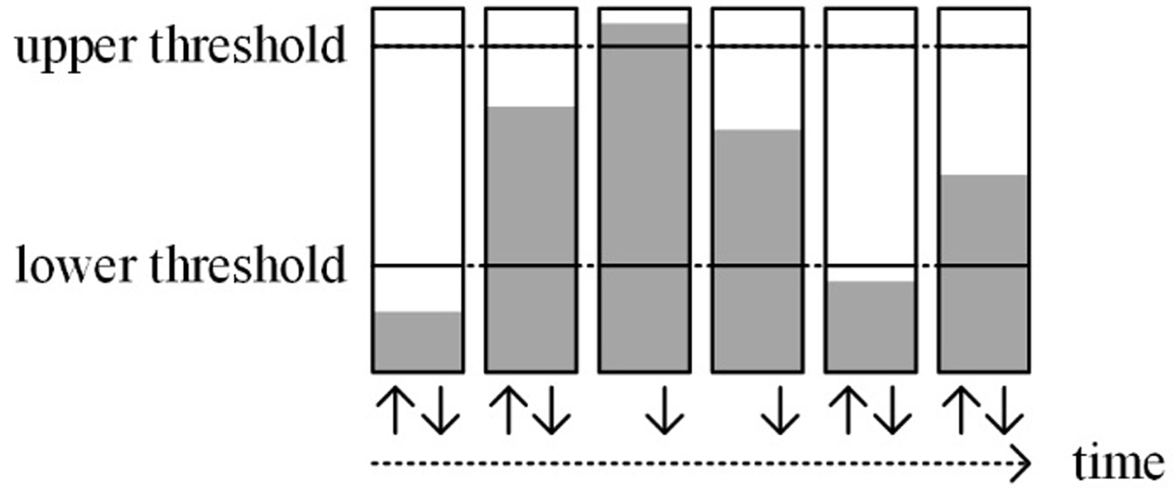
Since datagram loss is inevitable, the deeper the buffer, the smoother the data transmission. But the minimum depth of the buffer is required to hold the back-to-back transmission [11]. For normal Ethernet frames, the length is set between 64 and 1518 octets (without the 8-octet header). Therefore, the buffer depth cannot be less than 2*1518 words. Considering the simplicity of the RAM address access logic, the buffer depth is set at the nth power of 2, and hence the buffer depth cannot be less than 4096 words [12].
As an optical wireless communication technology, VLC is different from copper-wire communication because its link can be cut out by external interference. Figure 5 describes one situation when the link goes down: the link is blocked, but the transmitting logic does not know the error and keeps sending data; when the link is reconnected, the receiver side may receive fragmented segments but treat them as legal frames. Therefore, the receiving logic should check every segment received from the deserializer, mark the fragments, and mask the transmission of the fragments in further processing logic. Such operation detects and discards erroneous segments, and recovers transmission when the link is reconnected.
Frame transmission when the VLC channel is blocked.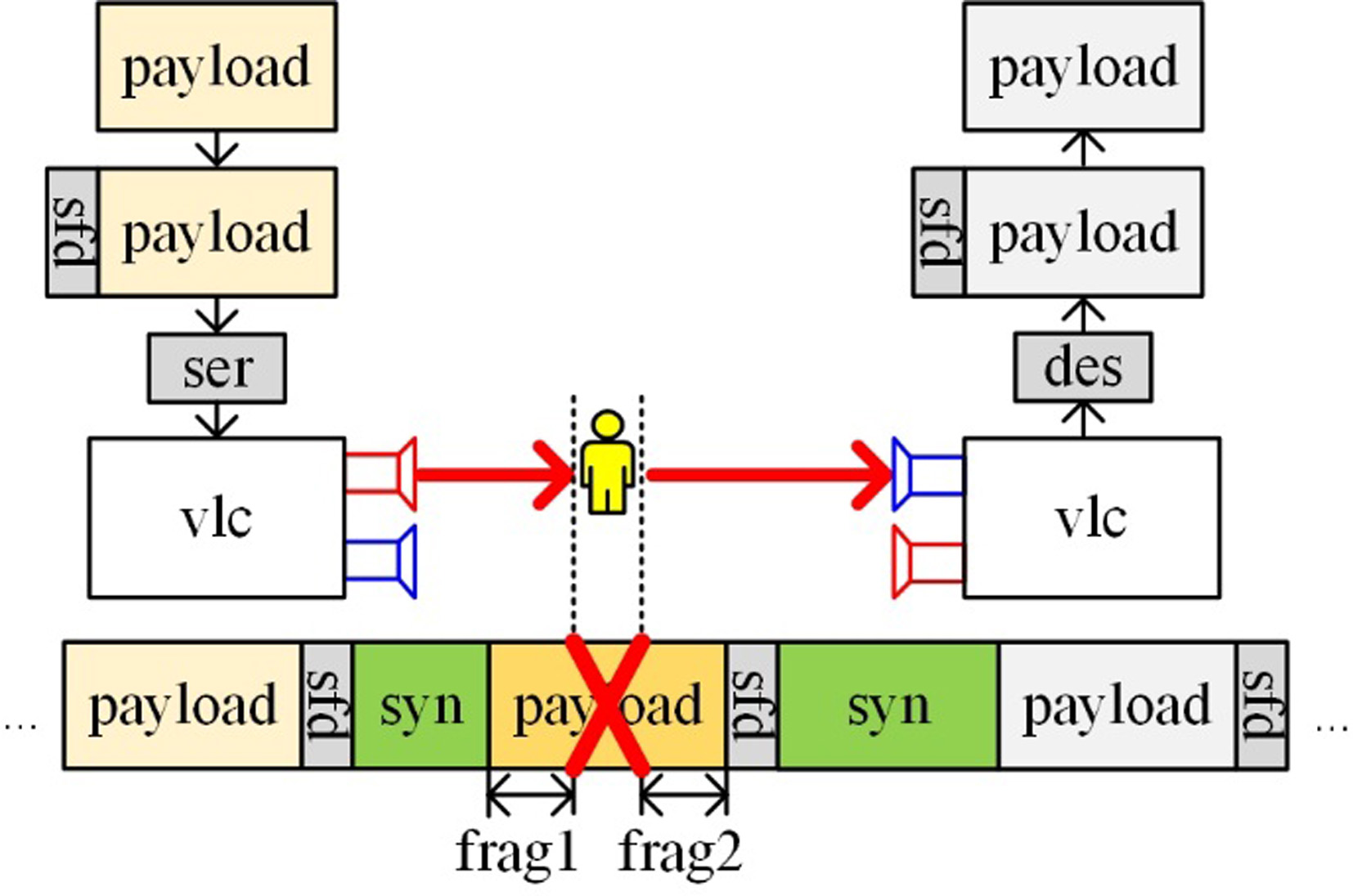
In Fig. 5, there are two types of fragments: “front-cutoff” as “frag1”, and “end-cutoff” as “frag2”. By inserting start-frame delimiter (SFD) before a frame, the “front-cutoff” problem can be solved by detecting SFD when the receiving logic is in standby mode, since “frag1” does not have SFD. For the “end-cutoff”, the loss-of-lock signal (nLOCK, active low when the receiver clock is locked in the design) generated by the deserializer can be used. When the link is down, the deserializer cannot recover clock, and thus nLOCK goes high. When nLOCK is detected low again during the receiving of a frame after an SFD is detected, it is certain that the erroneous segment is received.
For point-to-point communication, the frequency deviation of oscillators between device A and B is inevitable. Therefore, an elastic buffer logic is used to neutralize such deviation [13]. In this design, the buffer balances the rate mismatch by inserting or deleting 8B10B control words during the IFGs. Figure 6 and Fig. 7 describe such mechanism, in which “syn” means synchronizing word used in the design, “syn
When the local clock is slower than the recovered clock.
When the local clock is faster than the recovered clock.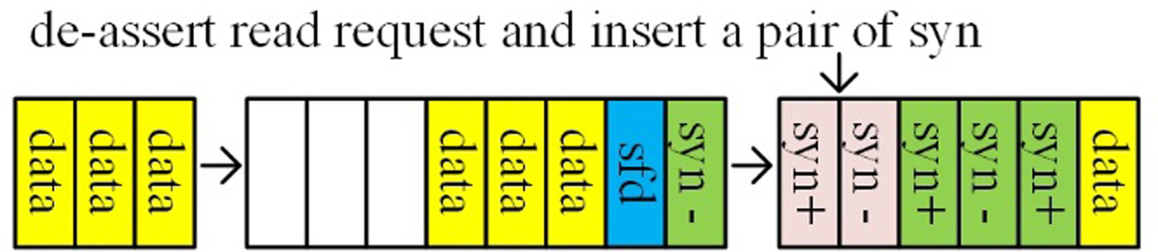
When the buffer is filling, the buffer logic in recovered clock domain should write fewer data words into the buffer. This is done by de-asserting write enable of the buffer during IFGs, equivalent to deleting data. When the buffer is emptying, i.e. the local clock frequency is higher than the recovered clock frequency, the buffer logic in local clock domain should read fewer data words from the buffer and insert control words to extend the IFG. The control word K28D5 is used as insertion symbol during IFGs, by inserting and deleting in pairs to implement the elastic buffering mechanism. The insertion and deletion should be in pairs to make sure the 8B10B words are balanced in running disparity so that the 8B10B decoder performs correct decoding.
Proving the basic function of a single adapter system
In order to prove that the proposed adapter is functional as expected, we first do the self-loopback test of a single adapter. We connect the output of the serializer to the input of the deserializer at the transceiver side and plug the adapter into PC with Ethernet cable, as shown in Fig. 8. And Wireshark is used to monitor the status of the NIC. The self-loopback result captured at some time is shown in Fig. 9.
Self-loopback of a single adapter.
Self-loopback result of a single adapter.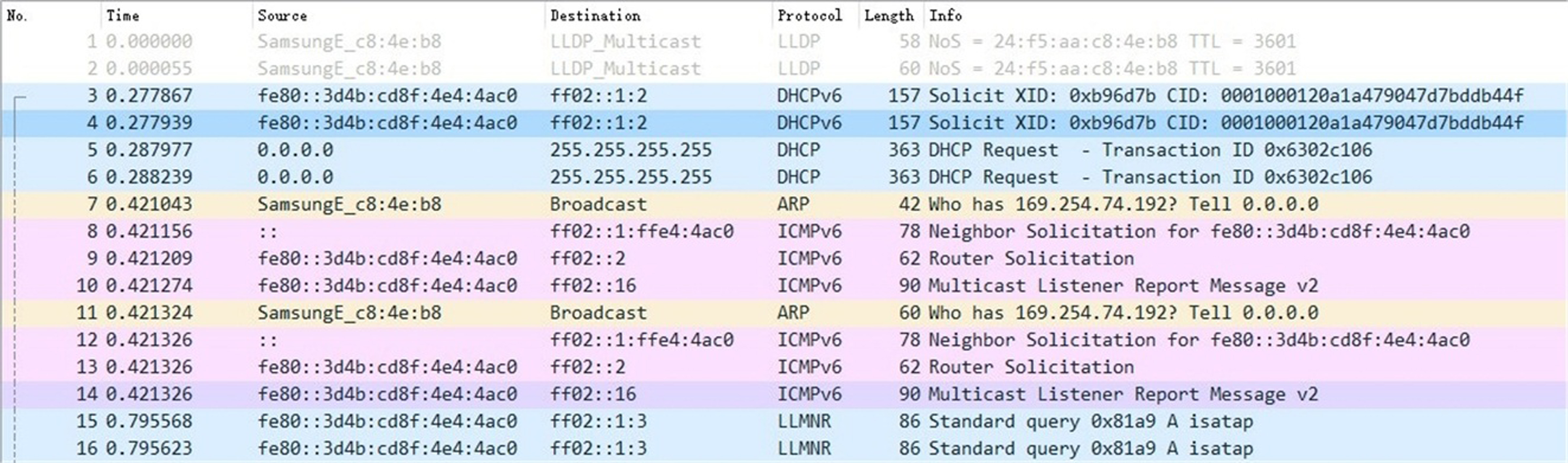
From Fig. 9, we see the frames numbering from 1 to 16 are in 8 pairs. In each pair, the frame with smaller index is the frame sent from PC and the frame with bigger index is the frame sent from the adapter and received by the PC. All pairs are the same in length, except from the pair with No. 1 and No. 2, and the pair with No. 7 and No. 11. It is normal because the actual length is less than 60 octets and padding is done for these frames, and thus the length of the received frame is added up to 60 octets, which is still the correct frame. Therefore, the basic function of a single adapter system is proved correct.
In order to test the system performance at point-to-point communication, the second experiment is conducted by sending loads of Ethernet frames to PC to test the peak rate of data running on the VLC channel when using a pair of designed adapters. Each adapter is connected to a pair of VLC transceivers. The speed test software used in the experiment is NerPerSection 14. It configures itself automatically and detects the current access medium to the Internet.
Simplified block diagram of the Ethernet frame generator.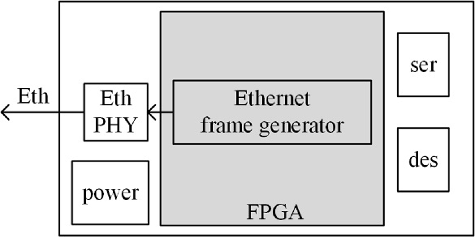
Speed test result captured from PC (with the generator directly connected to PC).
Simplified diagram of the test system.
In the test, the length of Ethernet frame varies from 64 to 1518 octets and the IFG is set to its minimum value of 96 bit-time in Gigabit mode. For convenience, we used a third adapter of the same design and configured its FPGA to send the continuous frames as described. The simplified block diagram of such Ethernet frame generator using the designed adapter is shown in Fig. 10. When the frame generator is directly connected to PC, the result captured from PC is shown in Fig. 11, where the average data rate reaches 988 Mbps and the maximum data rate hits 1.0 Gbps when the frame length is 1518 octets.
Speed test result captured from PC (with VLC transceivers).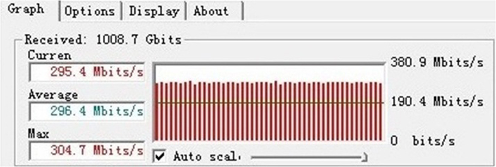
Block diagram of the FTP test system.
FTP test result.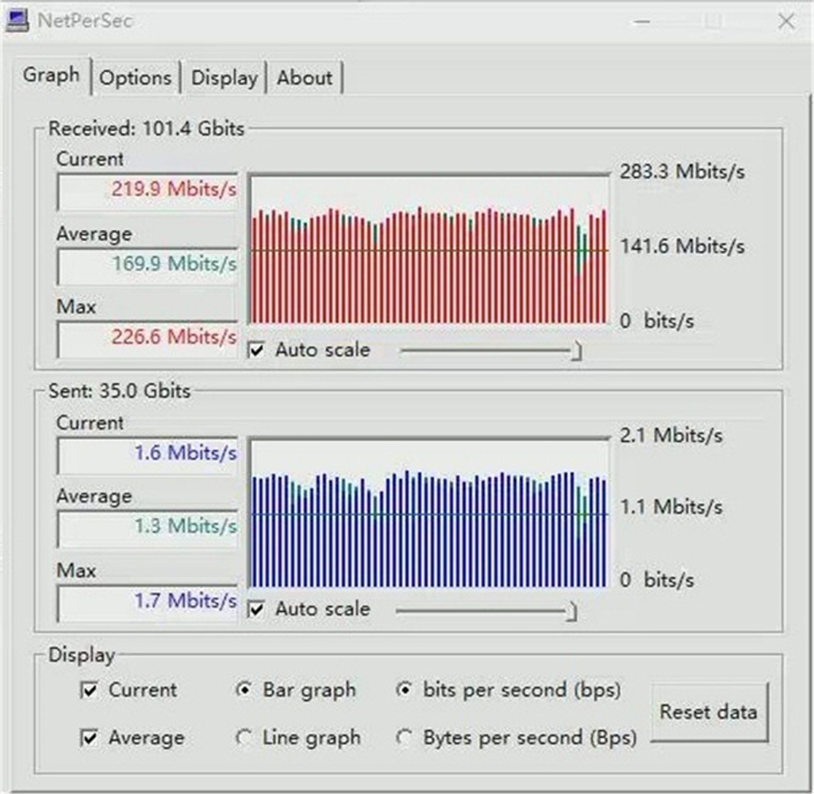
After this, we connected the frame generator to the complete test system, as shown in Fig. 12, where “3” is the frame generator, and “1” and “2” are the adapters under test. The speed test result captured from PC at some time period is shown in Fig. 13.
From Fig. 13 we can see that the average speed stays at almost 300 Mbps. It means that when the number of buffered data in the adapter is above the upper threshold, the adapter blocks oncoming data and reads out the buffered data. Such mechanism is able to ensure the maximum data rate on VLC channel is 300 Mbps. Therefore, the adapter is proved feasible and at its best performance in this 300 Mbps situation.
In this section, we test the performance of the adapters by running File Transfer Protocol (FTP). Figure 14 demonstrates the simplified block diagram of the FTP test system. The FTP application software used is FileZilla [15]. The test result is shown in Fig. 15. Here we can see that the maximum data rate reaches 226.6 Mbps at some time. This means that the performance stays at a relatively high level. The maximum performance will be closer to the maximum data rate of the current VLC channel when deeper buffer is used on the high-to-low bandwidth direction.
Conclusion
In this paper, we propose the design of an Ethernet adapter. We have described the necessity of such system and elaborated the function of every building block. Test results show that at 1000BASE-T duplex mode, the adapter ensures the maximum real-time net data rate of 300 Mbps running on VLC channel. Besides, the flexibility of FPGA enables that the adapter can be configured at different maximum data rate. Use of several pairs of adapters can also implement multi-channel bonding to increase the total data rate, and cascading, acting as relay for a longer distance. We will continue to optimize the adapter design based on FPGA implementation to obtain stable performance in high speed applications.
Footnotes
Acknowledgments
This research was partially supported by the National Key Research and Development Program of China (2017YFB0403604) and supported by Tianjin Key Laboratory of Optoelectronic Sensor and Sensing Network Technology.