
Abstract
Aiming to improving the manual inspection process of the elevator compensation chain, an automatic vision inspection system for detecting surface cracks of the welding joint is presented. To this end, firstly, an image acquisition system is designed to make the gray level of cracks obviously distinct from background in the captured image, which can effectively simplify the image segmentation algorithm. Then, on the basis of enhancement and de-noising of ROI image, the threshold segmentation and morphological features determination are employed to meet the demands of detection accuracy and time efficiency under the complex background and noise interference. Experimental results demonstrate that the system has good adaptability to various cracks and has achieved good performance in detection accuracy and time efficiency.
Introduction
Elevator compensation chain (hereinafter referred to as the chain) is the key component which is used to balance the weight of the wire rope and the accompanying cable during elevator running. Its quality directly affects the stability and safety of the elevator, so it needs to be pre-inspected to maintain good reliability. As the elevator market enters the new installation and maintenance period, the demand of the chain is huge. However, now there is no dedicated automatic detection equipment. Defect detection of the chain can only rely on human observations, which leads to high labor intensity, low efficiency, and missing detection due to visual fatigue, individual differences, and so on. Therefore, the enterprise has an urgent demand for efficient, accurate and reliable automated defect detection system of the chain. In recent years, replacing human eyes with machine vision has become an important means of modern industrial inspection to do the surface defects detection [1, 2, 3, 4, 5, 6, 7, 8].
As shown in Fig. 1, the chain is hollow ring and intersects 90 degree between two adjacent chain rings. The chain ring surface is stained and rusty, curve and rough, galvanized and reflective, which makes it difficult to detect the surface cracks of the chain image. The depth, length and shape of surface crack at weld joint of the chain are different, and the position of the weld joint is not fixed on one side. The gray value of the crack in the chain image is affected by the depth of the crack. The deeper the crack depth is, the smaller the gray value is. If we use some techniques to make the gray level of different cracks obviously distinct from the background, the threshold segmentation algorithm will become very simple, efficient and reliable. Therefore, under the interference of noise and complex background, in order to meet the demands of high accuracy and time efficiency, it is key to obtain a high contrast image and appropriate defect segmentation algorithm.
Various cracks at welding joint of the chain image.
The main approaches for obtaining high contrast images include: proper lighting system, de-noising and enhancement algorithms. Generally, a proper lighting system is the first choice for industrial product image detection. Based on analysis of the object to be detected and defect features, a high contrast image can be obtained by designing a suitable lighting system. For example, low angle light helps to highlight cracks in the background, and backlighting helps to highlight the contour of the object in the background. For irregular objects such as the chain, it is necessary to design combination light source on the basis of comprehensive considering the reflection, diffuse reflection and refraction of light. In addition, sometimes uneven illumination also needs to be processed. Image de-noising is also essential in the inspection system. In general, image de-noising algorithms can be divided two categories. One is methods based on the spatial domain, and the other is methods based on the transformation domain. The spatial domain-based de-noising method can modify the pixel’s gray value directly, such as mean filter, median filter, Gaussian filter and so on. The spatial domain filter can be used to remove noise, but it will inevitably blur the edges and textures. The de-noising methods based on transformation domain transform the image to the frequency domain, such as Fourier transformation, wavelet transformation, then modify the transformation coefficients according to certain criterion, such as Bayes threshold, finally perform inverse transformation and get de-noising image. The de-noising methods based on transformation domain achieve good performance in image de-noising, but for the speckle noise or irregular block, the effect is not ideal enough. The image de-noising method based on partial differential equation model combines the advantages of mathematical theory and image processing, and can remove noise while preserving edge information. The optimized total variation (TV) has significant de-noising effect due to anisotropy and other advantages. Common algorithms for industrial defect segmentation include threshold segmentation, texture analysis [9], watershed method [10, 11, 12] and filter based approaches. These methods are also used for defect determination in conjunction with morphological features. Threshold segmentation is the most commonly edge extraction method. There are many threshold segmentation methods, such as fixed threshold, dynamic threshold and adaptive threshold techniques. Filter based approaches can be divided into three categories: spatial domain, frequency domain and transformation based techniques. For the spatial domain filter, such as Sobel, Robert, Canny and Laplacian operator, edge in the image is extracted via gradient. For the frequency domain filter, such as Gabor filter [13], image is transformed into the Fourier domain, then, processed by filter function, finally, re-transformed into the spatial domain to extract defects. The transformation based approaches have good performance on edge detection, such as wavelet transform [14, 15], contourlet transform [16, 17], non-subsampled contourlet transform [18, 19]. In addition, there are some defect segmentation methods such as active contour models based [20] and Gaussian mixture model based [21]. For various defect segmentation methods, some methods have fast speed but poor accuracy. Some methods have high accuracy but slow speed due to complex computation [22]. For the industrial defect detection system, it is necessary to meet the detection accuracy and time efficiency simultaneously. Compared to other methods, the advantages of threshold segmentation method are simple calculation, high efficiency and easy to implement in algorithm. It is widely used in the application of emphasis on computing efficiency. It is very effective for the image with high contrast between the target and the background. In this paper, we present an automatic vision inspection system for detecting surface defects of the chain. To this end, firstly, aiming to obtain defect images with high contrast under the influence of various factors, we design an image acquisition system which is helpful to simplify the defect detection algorithm. Then, we extract the ROI(Region of Interest) according to the spatial location of the defects, which can decrease computation burden and eliminate the unnecessary noise by narrowing the detection range. After the ROI image is enhanced by linear contrast stretch and de-noised by TV method, the threshold segmentation and morphological features determination are used to meet the detection accuracy and time efficiency demands of different kinds of defects. Finally, the detection result and the location information of the defect chain ring are sent to the binding wire machine via a serial port to realize the physical marking. Experimental results demonstrate that the system has good adaptability to various defects and has achieved good performance in detection accuracy and time efficiency.
The rest of the paper is organized as follows. In Section 2, the system overview is described. In Section 3, the combination light source using for image acquisition and inspection method for the crack defect are described in detail. In Section 4, the experimental results are illustrated. Finally, the conclusion is made in Section 5.
The proposed automatic vision inspection system mainly includes: the chain traction unit, image acquisition unit, defect detection software, defect marking unit and control unit. Due to the flexibility, the chain must be straightened during defect detection so that defects in different positions can be detected. For this purpose, we designed the chain traction unit consisting of motor, gear reducer, sprocket, several guide devices and wheels. The position of welding joint with surface crack may not be fixed on one side of the chain ring, so we design two image acquisition units in the vision inspection system. Each image acquisition unit contains two sets of industrial cameras, lenses and composite light sources. Because the chain ring is connected to each other, the defect chain ring cannot be peeled off directly, so the defect chain ring can only be marked. So we designed the defects marking unit consisting of a binding wire machine and a distance measuring unit. The distance measuring unit mainly includes: synchronous belt & pulley, pulley shaft, spring, pressure plate and encoder. The chain passes between the synchronous belt and the pressure plate. The proper pressure between the chain and the synchronous belt is maintained by pressing plate and spring. And the encoder assembled with pulley shaft is driven by the friction between the chain and the synchronous belt. The defect detection software runs on the industrial personal computer. The control unit use ARM processer to process various sensors, image acquisition trigger, encoder and other signals, as well as the control of traction motor and binding wire machine. The 485 interface is used for communication between industrial personal machine and ARM processer to transmit the inspection result signal.
As shown in Fig. 2, the chain is driven by the chain traction unit to realize automatic and continuous feeding. The sensors are installed in the appropriate position in front of the image acquisition unit. The cameras are triggered by the sensors. We can keep the chain ring in the middle of the field of view of camera by adjusting the location of the sensors. After determining the location of the sensors by experiments, the location is no longer changed after the system is deployed. When the chain passes, the trigger signal is transferred to the control unit, and the image acquisition unit is triggered automatically to capture the image. The images processed by the defect detection software are divided into two categories: OK and NG. At the same time, the detection result and location information of the chain ring with cracks are sent to the control unit, and the distance measuring unit begins to measure the distance via the encoder. When the measured distance is equal to the set distance between the image acquisition unit and the defect marking unit, the control unit sends the marking signal to the binding wire machine to realize the physical marking of the chain ring with defects.
The detailed
Image acquisition
Under complex background and noise interference, in order to meet high accuracy and time efficiency of the chain inspection system, it is one of the keys to design a suitable image acquisition system to capture high contrast image. Considering the characteristics of the chain structure and defect distribution, the key problems to be solved by the image acquisition system include: stability of image processing, proper lighting system and layout of cameras and lens. Because the chain is flexible in whole and intersects 90 degrees between two adjacent chain rings, we cannot get the whole image if the chain is distorted or vibrated in movement. The instability of the imaging process will lead to the failure of the entire inspection system. To ensure the stability of the imaging process, we designed chain traction unit consisting of motor, gear reducer, sprocket, several guide devices and wheels. The chain guide device is designed with a cross groove matching the chain structure. To adapt to different sizes of chains, guiding devices with suitable size can be manufactured in advance according to the size of the chain without changing its structural design. When the system detects chains of other sizes, it only needs to replace the corresponding guiding devices. As shown in Fig. 2, the chain passes through several guide devices, guide wheels, and a sprocket wheel. The chain is straightened by the motor through drive sprocket. We assign a guide device at regular intervals, which can support and guide the chain to prevent it from distortion and vibration in movement.
Overall framework of the proposed vision inspection system.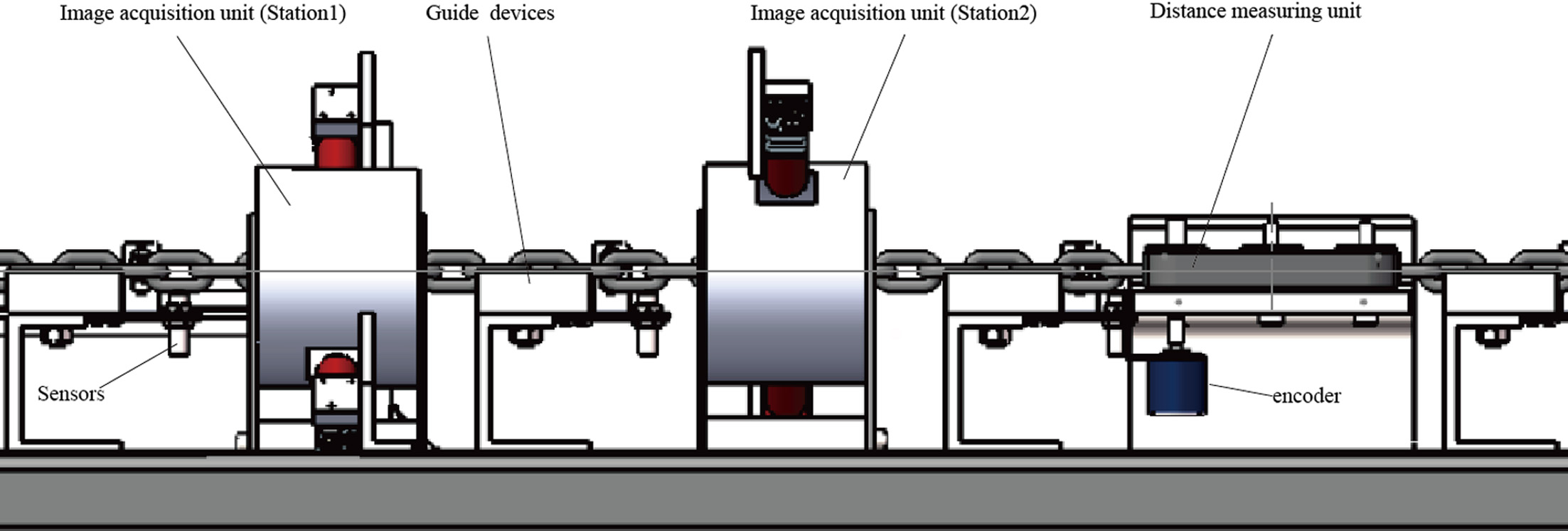
Image acquisition unit.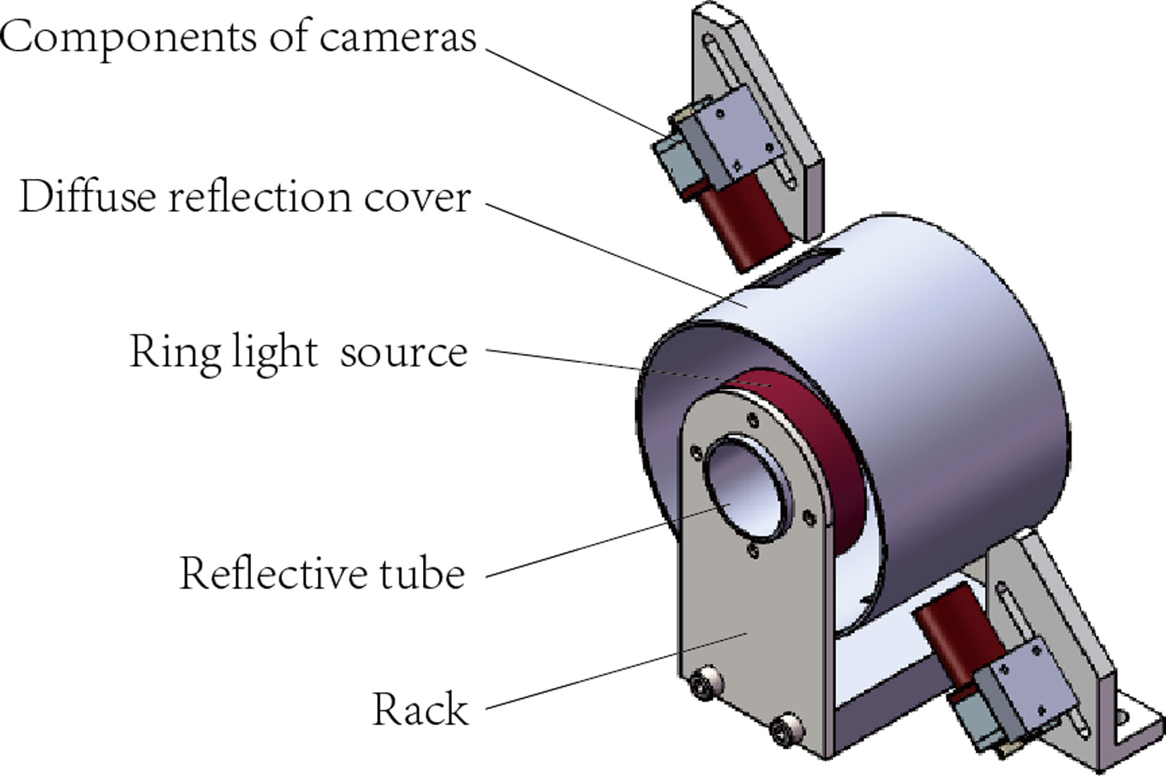
Generally, for industrial product image detection, proper lighting system is the first choice to get a high contrast image. The proper lighting system can highlight differences between the defect and the background. Based on analyzing the characteristics of the weld surface crack and lots of experiments, we found that all cracks have a certain depth and length, low angle light source can highlight the crack and the gray value of crack is less than that of the surrounding flat region. The difference of gray value between crack and surrounding region is very helpful to threshold segmentation of the chain image. However, the angle of the low angle light source is fixed and the light range is limited, a single light source cannot meet the defect detection requirements. So we design a combination light source composed of two ring light source, reflective tube and a diffuse reflection cover. As shown in Fig. 3, two low angle ring light sources are arranged face to face to highlight edges and textures. The reflective tube is installed in the hole of the ring light source to reflect light onto the diffuse reflection cover. The diffuse reflection cover is used to obtain uniform illumination on the chain surface. Two rectangle holes on the diffuse reflection cover faced to camera can form a black block in the middle of the chain image, which can be used as a positioning mark. The optimal distance between the two ring light sources is determined manually by experiments before the whole system is deployed. In our experiments, we first install the combined light source, cameras, lens and connect the computer, then adjust the distance while observing the effect of the captured images on the screen until we get the best effect. After the distance is determined by experiments, and the system is deployed, since the reflective tube and the diffuse reflection cover can reflect the light evenly to the surface of the chain, the combined light source can ensure the uniform effect of chain images without adjusting the distance. As shown in Fig. 3, there are four cameras and lens in two image acquisition units. The four cameras are arranged in pairs and cover the entire 360-degree circle range, which can capture the defect images in each position. Several examples of the captured images are shown in Fig. 1. The ring light source is a low angle light source with limited illumination range. The same ring light source cannot adapt to different sizes of chains. In our design, since the reflective tube and the diffuse reflection cover can reflect the light evenly to the surface of the chain, the combined light source can broaden the illumination range, which can adapt to different sizes of the chain as long as the outer contour size of the chain is smaller than the inner hole size of the ring light source. For the chains with larger size, we can replace the ring light source with appropriate size without changing the structure design of the combined light source.
As shown in Fig. 1, due to the designed image acquisition system, especially the combination light source, the crack is obviously different from the surrounding area in the chain image, such as gray value and morphological features. This ensures that we can use threshold to segment the crack defect, which makes the inspection method very simple and meets the requirements of high accuracy and time efficiency. The inspection method mainly includes the following steps:
Step 1: ROI extraction
The welding joint has always located in the middle of the chain duo to the manufacturing technology. According to the spatial location of the welding joint, we can extract the ROI (Region of Interest) before detecting the crack defect, which can not only decrease computation burden, but also eliminate the unnecessary noise by narrowing the detection range. Figure 4 shows the process of ROI extraction. We first extract the black block and white block by threshold segmentation. Then, we merge the black and white blocks, and calculate the center coordinates of the merged region to obtain the center line of the chain. Finally, we generate the ROI automatically according to the center coordinates of the chain, which can adapt different sizes of chain rings.
Step 2: Image de-noising based on TV model
Total Variation (TV) is a classical de-noising model in image processing. TV model can not only remove the noise in the image, but also preserve the structure information of the image effectively. The image de-noising using TV model [23] can be attributed to the following minimization problem.
Where
Process of ROI extraction. (a) Original chain image. (b) Extraction of the black block. (c) Extraction the union of the black and white blocks, and calculating the center line. (d) Extraction the ROI according to the center line.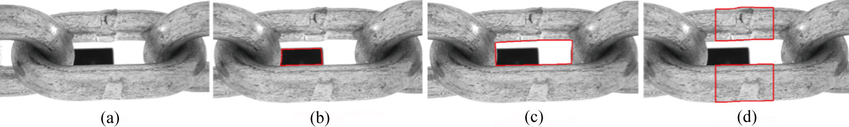
Step 3: The crack defect detection
In this step, firstly, we use linear contrast stretch to further enhance the contrast of ROI image, and the linear contrast stretch equation is as follows.
Where
Next, threshold segmentation is performed to get the candidate region of the crack defect.
Where
Where
Process of the crack defects detection. (a) Original ROI image. (b) De-noising image after performing TV method.(c) Candidate region of crack defect after performing image enhancement and threshold segmentation. (d) Detected crack defect after performing morphological determination. (e) Crack defect displayed on the original ROI image.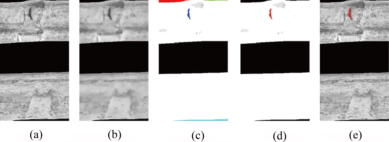
Step 4: Morphological feature extraction and defect determination
After extracting the candidate region of crack defect, In order to deal with the disturbance such as stain and rust, we should further determine whether it is a defect based on its morphological characteristics. Through a large number of defect sample analysis, we found that morphological characteristics of crack defect are obviously difference from those of stain and rust, such as length and width ratio, angle
Where
Where L is the length of the crack defect contour and F is the area of the crack defect region.
Figure 5 illustrates the process of the crack defect detection.
The comparison experiment of different lighting schemes
For industrial visual inspection systems, the demands of high accuracy and time efficiency must be met. However, under complex background and noise interference, it is not easy to achieve those demands simultaneously. It is not appropriate to use a complicated algorithm with large computational complexity. So a proper lighting system is the first choice to get a high contrast image, which can highlight differences between the defect and the background. In general, low angle light source can highlight the crack and the gray value of crack is less than that of the surrounding flat region. Based on this, we conduct a light source comparison experiment to validate the effectiveness of the combination light source proposed in this paper. We compare three lighting scheme. The first scheme uses two low angle ring light sources arranged face to face without diffuse reflective cover and reflection tube. The second scheme uses a dome light source. The third scheme uses the proposed combination light source.
As shown in Fig. 6, in the first column, due to the limited angle of the low angle ring light source and the distance between two ring light sources, the crack defect in the image is not salient enough. In the second column, due to using the dome light source, the gray feature of crack defect in the image is different from the surrounding region, but the crack is a little blurry. In the third column, due to using the proposed combination light source, the crack in the image is salient and the illumination of the whole image is relatively uniform. There are three main reasons for this good effect. Two ring light sources are used to distinguish the crack from the surrounding area. The diffuse reflection cover is used to obtain uniform illumination on the chain surface and make the dark regions brighter. The reflective tube is used to eliminate the bright spots in the image.
The experiment for crack defect detection
In order to evaluate the detection accuracy and time efficiency of the proposed vision inspection system, we conduct the crack defect detection experiment using 1000 chain rings (including 43 defective chain rings). For chain images with defects, we define the number of defective images that can be correctly detected as A, and the number of defective images that cannot be detected as B. For chain images without defects, we define the number of images that are considered defective as C, and the number of images that are considered non-defective as D. The calculation equation for the detection accuracy rate is defined as follows:
As shown in Table 1, the detection accuracy rate is 97.4%, there are no missed detection and a handful of false detections, which can meet the system requirements. As shown in Table 2, it takes 1.5 seconds each chain ring to complete the detection with manual inspection. Using the proposed automatic vision inspection system, 0.6 second each chain ring is enough to complete the detection.
Experiment data on detection accuracy rate
Comparison of detection efficiency
Comparison experiment results of different light sources. (a) Experimental results of using two low angle ring light sources arranged face to face without diffuse reflective cover and reflection tube. (b) Experimental results of using dome light source. (c) Experimental results of using the proposed combination light source.
Experimental results of various crack defects detection. (a) Original ROI image. (b) Results of image de-noising via TV method. (c) Results of performing image enhancement. (d) Candidate region of crack defect after performing threshold segmentation and closing operation. (e) Crack defects determined by morphological features. (f) Crack defects displayed on the original ROI image.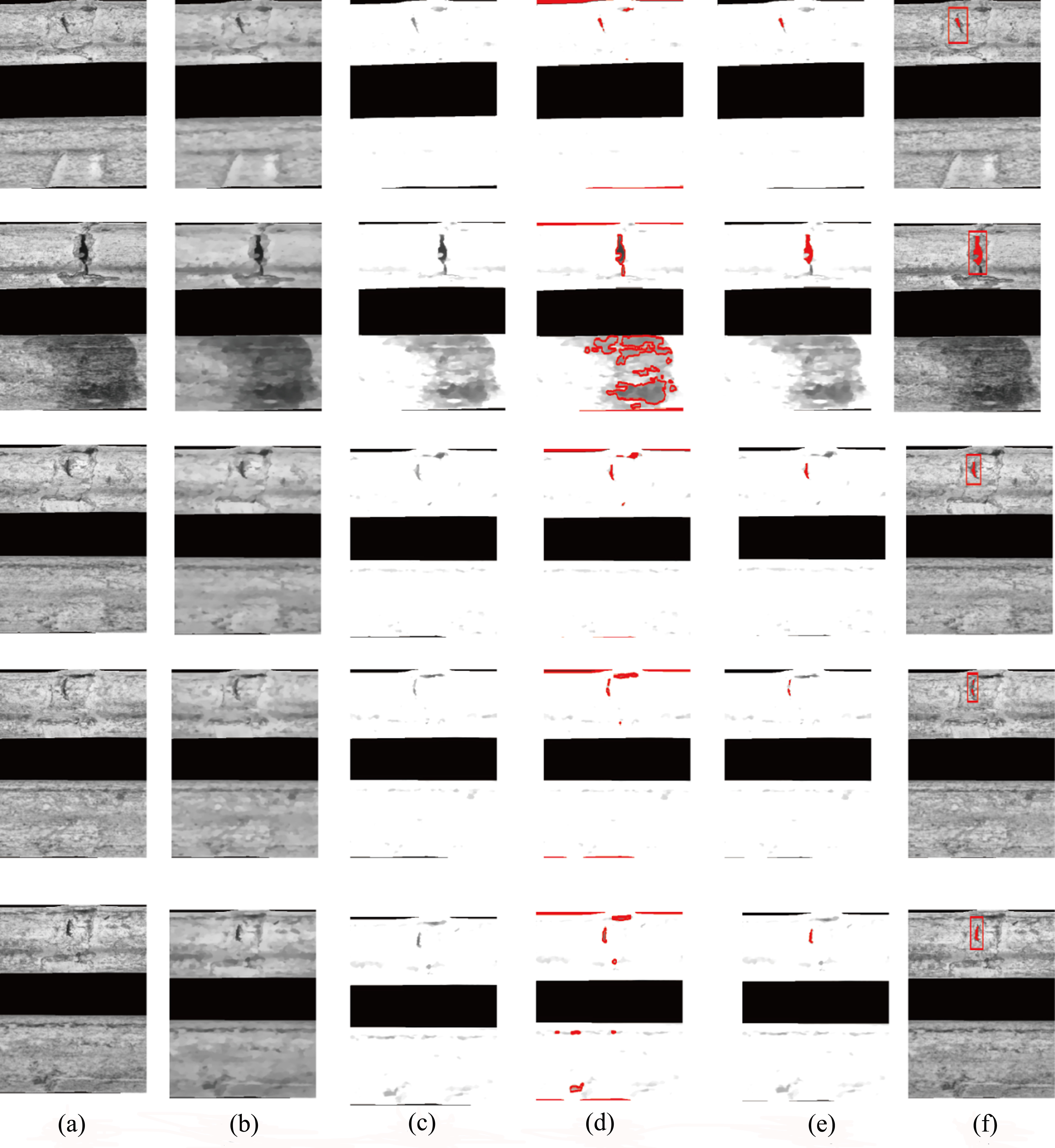
Figure 7 illustrates some examples of the defect detection experiment results. After ROI extraction, the crack defects of different length, depth and shape were detected using the proposed method. The first column is the original ROI image. The second column is the TV de-noising results of ROI images, and the third column is the image enhancement results. In the fourth column, the crack region is obtained after threshold segmentation, which also included some stains, rust spots and other interference. As shown in the fifth column, the interference information is removed, and only the crack defect is remained via morphological features. The experimental results demonstrate that the system has achieved good performance in detection accuracy.
As shown in the first column of Fig. 7, the crack defect is obviously different from the adjacent region. So it is possible to do threshold segmentation according to gray scale. However, the gray value of some stains or rust spots in the ROI image is also within the threshold range. Thus, we have to do enhancement and de-noising before threshold segmentation.
As shown in the third column of Fig. 7, after de-noising and contrast stretch, the gray scale of the cracks is far smaller than that of the surrounding region, the gray value of the background is near 255, and the gray values of cracks are far lower than 150. So the range of threshold used for image segmentation is set 0 to 150, which can adapt to different crack defects.
As shown in the fourth column of Fig. 7, the crack defect and stains or rust spots with low gray value are detected after threshold segmentation. Stains and rust spots are usually irregular dots or blocks. So we extract the crack defect and remove the interferences in terms of morphological features, such as ratio of length and width, angle Phi and ratio of circumference and area. The angle Phi of the crack defect is approximately perpendicular to the horizontal direction. The length and width ratio of the crack defect is usually greater than 2. Stain and rust spot regions with low gray value in the image can be removed according to angle Phi and length and width ratio. For stain and rust spot with irregular shape, the ratio of circumference and area is much larger than that of the crack defects. It can be removed in terms of the feature. So no matter how many rust stains there are, only the cracks can be selected. No matter whether the crack is one or more, the system determines that there are defects on welding joints of the chain. So, the proposed method can adapt to welding joints with a large number of rusts and multiple cracks. For the images collected by ring light source, the deeper the crack is, the lower the gray value is. Because the depth of the surface crack on welding joints is far bigger than that of the scratches, the gray value of cracks is far smaller than that of scratches. After de-noising and contrast stretch, the gray value of scratches is near that of background. So there are no scratches shown in Fig. 7(c).
In our software, we design the feature parameters of crack defects as variables, such as length and width ratio, angle Phi, ratio of circumference and area. These feature parameters are universal for cracks with different sizes and shapes. When the system is deployed, it is only necessary to set the range of these parameters on the user interface window without modifying the algorithm to adapt to cracks with various sizes and shapes on the chains of different sizes.
Due to the proposed inspection method and image acquisition system, the detection accuracy rate achieves to 97.4%, and 0.6 second each chain ring is enough to complete the detection. The experiment results demonstrate that the proposed vision inspection system achieves good performance both detection accuracy and time efficiency.
In this paper, an automatic vision inspection system with high detection accuracy and time efficiency approaches for detecting surface crack defect on welding joint of the chain is presented. Experimental results demonstrate that the vision inspection system has good performance. The system achieves good performance mainly due to the combination of two critical elements: an image acquisition system, which can capture images with high contrast under the influence of various factors and simplify the defect detection algorithm; and the high detection accuracy and time efficiency inspection method, which can meet the demands of detection accuracy and time efficiency under the complex background and noise interference.
Footnotes
Acknowledgments
This work was supported by the prospective project of Industry, Education and Academy of Jiangsu Province China under Grant BY 2014077.