
Abstract
In order to solve the present problem of lacking of railway signal outdoor information monitoring technology, this research proposes a design program of outdoor information monitoring and communication unit. First, we introduce the characteristics of power line carrier communication and adopt the Hoffman coding as encoding mode. Second, the bus-powered is used as transmission mode and the content is transmitted in “data packet
Keywords
Introduction
Railway signal centralized monitoring system (CSM) is mainly used for monitoring the important parameters of indoor key signal equipment for 24 hours, and save important information to provide the basis for analyzing the status of equipment and accident causes [1]. However, due to technical level and economic constraints, signal centralized monitoring technology is rarely used in outdoor equipment. The way of monitoring the status of outdoor equipment through indoor acquisition information, instead of the field monitoring information of outdoor equipment, which is difficult to obtain the first-hand data of outdoor signal equipment characteristics and operating status [2].
Given that the outdoor signal equipment is exposed to the open environment, it is affected by temperature, weather, environment, power traction current, and other factors. Therefore, the outdoor information monitoring and communication technology needs to meet the basic functions of real-time, accuracy, and reliability. At present, the outdoor information is collected indoors, and it may be significantly different after affected by the environmental noise and cable consumption, which is difficult to timely and synthetically reflect the status of track circuit and trackside equipment. Therefore, we should strengthen the research on the application of outdoor signal equipment information monitoring communication technology.
With the rapid development of China high-speed railway industry, a lot of Chinese scholars have carried out the relevant research in the field of railway signal outdoor information monitoring technology. Based on the power line carrier communication technology, Fu Lang studied the outdoor information monitoring device and added it to the signal machine to realize the function of directly monitoring the voltage of signal light, so that the accurate current and voltage value can be monitored and the reliability of outdoor equipment can be improved [3]. Tang proposed a distributed railway signal centralized monitoring system based on ZigBee technology, and it can collect the railway signal outdoor information real-time [4]. Liu followed the various standards and specifications of development and design of monitoring system to develop a ZPW-2000 frequency-shift outdoor monitoring system which can collect the FSK frequency-shift signal, encode the frequency-shift signal, communicate long distance outdoors and analyze the fault of track circuit [5]. Cheng introduced the design program of outdoor information monitoring system using power line carrier communication technology and analyzed the availability of it, according to study the development state and characteristic of the power line carrier communication technology [6]. On the above basis, Cai et al. studied in depth the outdoor information collection technology, according to the actual field conditions [7]. Wu and Zhu used the power line carrier communication technology to design the outdoor information collection device, and introduced the key technology in great detail [8]. For the outdoor equipment of ZPW-2000 frequency shift track circuit, Cai and Zhang designed a comprehensive monitoring device, and tested its performance fully [9]. Liu also studied the application of outdoor information monitoring technology with power line carrier communication technology as the main body power, according to introduce the development status and characteristic of the power line carrier communication technology [10].
In summary, the present railway signal centralize monitoring system still has the defects of imperfect outdoor monitoring function and the research of outdoor information monitoring technology mainly focus on the theoretical stage. Hence, the practice of this technology is still inadequate. Considering the demand of real-time, accurate and comprehensive outdoor information monitoring technology, the number of communication cables between outdoor and indoor will be enormous. This research proposes a design program of railway signal outdoor information monitoring unit based on power line carrier communication technology, which can be compatible with the present signal centralized monitoring system and doesn’t need any out the additional cables. As a result, it can not only improve the capabilities of field monitoring and maintenance, but also reduce a lot of manpower and time cost.
Feasibility analysis of power line carrier communication
The principle of power line carrier communication
Power line carrier communication technology is an important technical means to achieve this research, which uses power lines as the communication media for transmitting the digital information [11, 12]. Its implementation is that the sending end modulates the information and sends it to the power line, then the receive end restores the information, so completes the communication function [13]. Figure 1 presents the principle of power line carrier communication which means the signal of sending end is modulated, filtered and amplified power by the modem, then send it to the power line by the special coupler, and receive end extracts the signal from the power line through the special coupler, finally obtain the original signal after demodulation and filter [14].
The principle of power line carrier communication.
In this study, the railway signal outdoor equipment information is monitored, and the power line is used as the transmission channel, so the communication environment is relatively bad. Therefore, it is necessary to analyze the characteristics of the power line carrier communication which is mainly divided into three types including line impedance, signal attenuation, noise interference and so on.
Line impedance
Line impedance is the generic term of resistance and reactance, and the resistance contains capacitance and inductance. When the power line is used as communication channel, there will be magnetic field and electric field around the power line, except the resistance of power line, there is capacitance and inductance between power lines. Hence, the impedance of power line is variable and irregular [15]. To improve the efficiency of the power line carrier communication, we should try to make the line impedance match the power line carrier communication system.
Signal attenuation
The signal attenuation phenomenon of signal transmission process also appears in the general power line or railway signal information transmission, because of the power line generates heat and radiation in the transmission process, so the carrier signal will be seriously attenuated with the increase of the frequency and the transmission distance. Research shows that the signal loss will increase with the increase of transmission distance and signal frequency in the cable transmission [13].
Noise interference
For any communication system, the noise will affect the quality of communication. Based on the previous studies [16, 17, 18, 19, 20, 21], we can divide the noise interference of low voltage power line channel into five types: colored background noise, narrowband noise, synchronized to the frequency of periodic impulse noise, asynchronous to the frequency of periodic impulse noise and asynchronous non-periodic impulse noise.
According to analyzing the feasibility of power line carrier communication, it can be seen that the advantage of power line carrier communication is that using the power line as the transmission channel, which has the characteristics of high reliability and less investment. In view of the above characteristics of power line carrier communication, it is necessary to study the information coding and transmission mode to meet the requirements of long-distance reliable transmission of railway signal outdoor information.
Information coding and transmission mode
Information coding mode
Due to the power line carrier communication has the characteristics of great signal attenuation, the large noise influences and lows the communication rate, which need to adopt coding program that possesses the error detection capability and very high efficiency [22]. The coding process includes data preprocess and information coding, according to the demand, this research adopts Hoffman coding mode to encode, and the transmission content adopts “data packet
Data preprocess
The collected information includes analog and switch variables, analog variables are converted to digital variables by the AD. Due to the limited communication rate of power line carrier communication, the collected data need to be preprocessed, so it can minimize the size of transmission data [23].
For example, the switch variables of signal light position and switch position can be directly represented by 0/1. Moreover, the analog variables of signal light voltage and switch machine working voltage need be processed by AD conversion, so that the data takes fewer bytes [7]. Such AD the signal light voltage is usually 220 V, and it need 1 byte, occupy 8 bits, while the signal light voltage is usually in the range of 220 V
Data encoding method
In order to improve the efficiency of information transmission, it needs to encode the information and remove the redundant components of the information source as much as possible, so that each transmission symbol can carry information as much as possible. According to Shannon theorem that the efficiency of variable-length code data transmission is better than fixed-length code data transmission, so Huffman coding mode is used to encode, and the 8-bit CRC is used for the error detection code [24].
Considering the information frequency, shortcodes are allocated to the information with higher frequency. Such as DZ220, the normal value is 210
The transmission content: “data packet
heartbeat packet” [25]
The transmission content adopts the variable mode, but the analog variables, such as the signal lamp voltage, switch machine voltage etc., changes very little in most cases. Moreover, if the allowed variation is in the normal range, and there is no need to transmit the information [26], so in this way will significantly reduce the amount of data on the bus. For example,
The variation of 220 V voltage can be set to 1 V, or even 2 V, which is very little, and if there is no change in the switch variables, such as the signal lamp position and turnout indication joint position, there is no need to transmit the information.
When the outdoor equipment has no change, the outdoor information monitoring unit does not transmit information to the indoor, and if the outdoor information monitoring unit fails or the communication of indoor and outdoor are interrupted, then the indoors host cannot receive the information. In order to distinguish two situations, the outdoor information monitoring unit will send the heartbeat packet to the indoor host periodically, due to the amount of heartbeat packet is very small, and the time of occupying the bus is very short, so it cannot affect the efficiency of outdoor information transmission by power line.
Information Transmission mode
In order to save the cable, this research adopts the power line carrier communication technology to transmit the outdoor information. Based on this, this study uses the bus to supply power, which means the power and data share the same channel, and all outdoor information monitoring units are parallelly connected on a 2-core line [27].
In this transmission mode, the spare cable connecting indoor and outdoor signal equipment, which is firstly connected with sub-boxes, then start from the branch boxes, until connect to each device. So the spare cable of each branch boxes can be used as a bus, and the outdoor equipment can be divided into some groups according to the connected cables, and one group occupies one bus, as shown in Fig. 2. Hence, this information transmission mode not only can increase the number of buses, but also can improve the communication efficiency of each device.
Information transmission mode.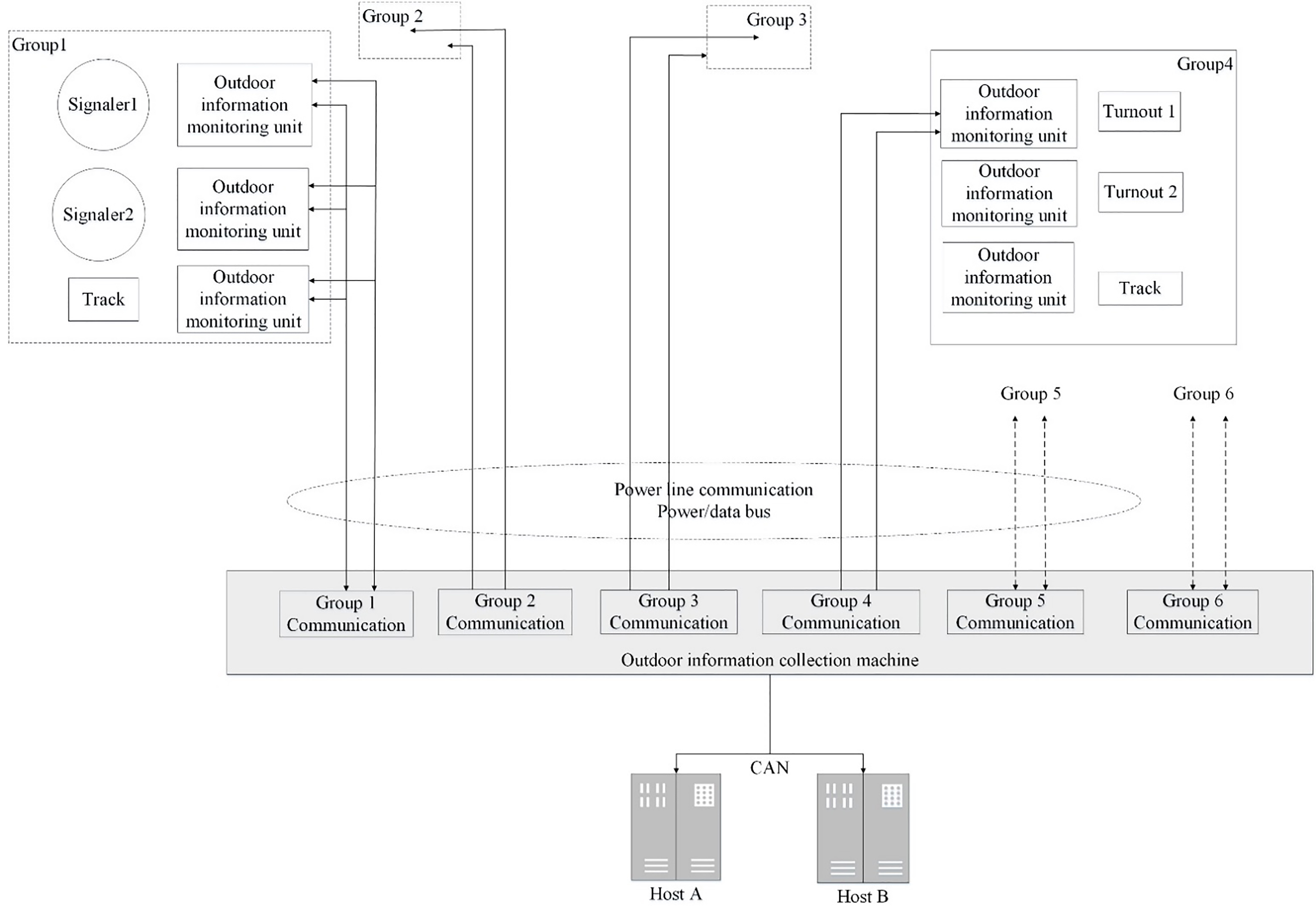
Based on the above research of power line carrier communication technology, information coding and transmission method, this section presents a complete design program of outdoor signal equipment information monitoring unit, which contains overall structure, working principle, hardware design and software design.
Overall structure
The designed monitoring unit is composed of a power supply unit, a power network interface, a signal-modulating module, a micro-controller and a collecting unit. The overall system structure is shown in Fig. 3.
The systematic structure of outdoor monitor unit.
As shown in Fig. 3, the collected data access to the monitoring unit through the acquisition interface, and the high-performance ARM7 series MCU is used for the micro-controller, which has 8 ADC interfaces, and analog variables can directly conduct the AD conversion, meanwhile the digital variable can be read directly and stored in a section of the buffer of micro-controller.
The working principle of the designed outdoor monitoring information unit is that after the acquired data is preprocessed, simplified and filtered, adopts the Huffman coding mode to encode, then the transmission content is in the form of “data packet
Hardware design
Chip selection
Micro-controller is the control core of this outdoor information monitoring system, which is mainly responsible for the coordinating and scheduling the detailed task of the whole system. Due to the data prerecession and coding require the processor have high computation speed and strong control function [28].
As well as, the chips must have the function of signal modulation and demodulation, and adaptive balanced amplification of signal, filter, and communication, etc. Besides, the cost of module and the economics of product are counted, so this study adopts ST7538 carrier chip. ST7538 carrier chip is a half-duplex, synchronous/asynchronous FSK (FM) modem chip designed for power line network communication in home and industry domain and it has the characteristics of powerful function, high integration, anti-interference technology and so on [29].
Micro-controller and ST7538 interface circuit
The serial communication mode is used between ST7538 carrier chip and micro-controller, which can use either synchronous mode or asynchronous mode. Connect the digital transmission interface of ST7538 with the UART interface of micro-controller, as shown in Fig. 4.
Micro-controller and ST7538 interface circuit.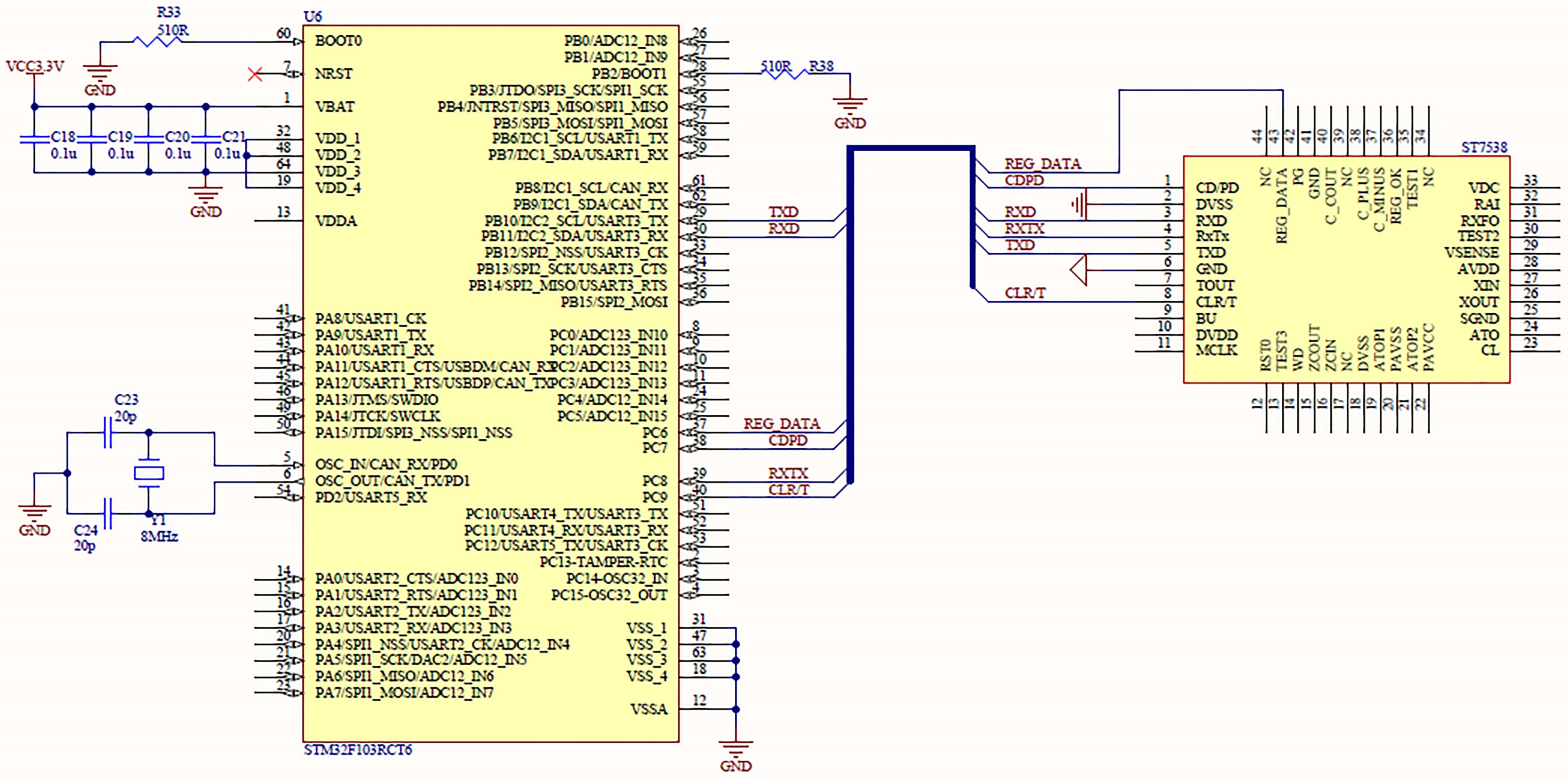
The power line interface circuit is used to connect the ST7538 carrier chip and power line chip, and its performance determines the communication effect, which is the key role to realize the power line carrier communication [30].The receiving signal channel is composed of coupling circuit, filtering circuit, protection circuit and voltage amplification circuit. And the transmission signal channel is composed of voltage amplification circuit, power amplification circuit, filter circuit, protection circuit and coupling circuit, as shown in Fig. 5.
Power line interface circuit.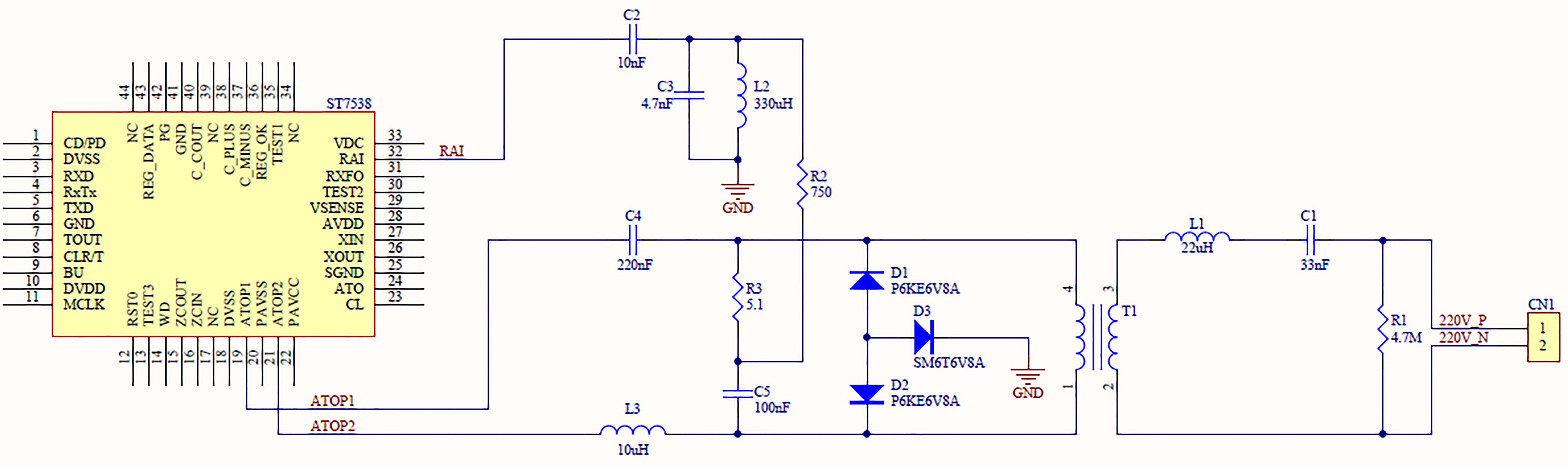
System principle block diagram of low voltage power line carrier communication is shown in Fig. 6. The detailed process can be seen from the graph, the data is sent by the main communication device, through the communication interface, and stores in a buffer zone of the microprocessor processing, after encoding, modulating, and finally coupled to the power line. At the other end of the power line, the data is coupled from the power line and receive it, then demodulated to the microcontroller, and finally send it to the communication device through the communication interface. The above is the flow of the designed system software, and realize the function of the monitoring outdoor information of railway signal centralized monitoring system.
System software flow diagram.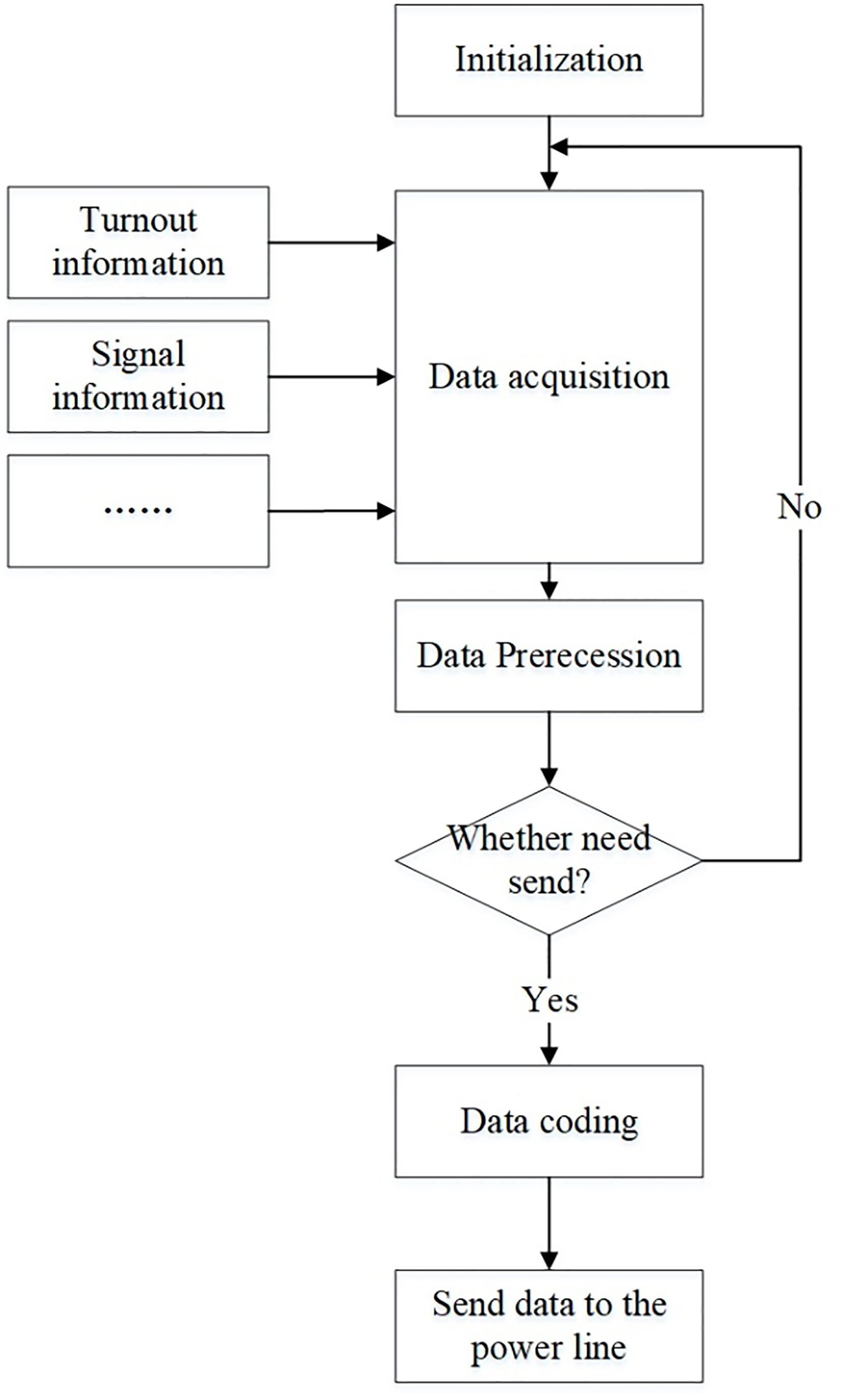
In order to verify the functional characteristics of the outdoor signal equipment information monitoring unit, according to the demand of actual environment, this research develops a monitoring unit for ZPW-2000 track circuit, and conducts the experiment in the laboratory. The experiment adopts a signal generator as the information acquisition end, and regards the monitoring unit A as the sending end, and the monitoring unit B as the receiving end. Then upload data to the PC through serial ports of the monitoring unit B, and PC end records the data through the serial assistant. The architecture of the test environment mainly consists signal generator, PC machine, acquisition unit and power line, as shown in Fig. 7.
The architecture of the test environment.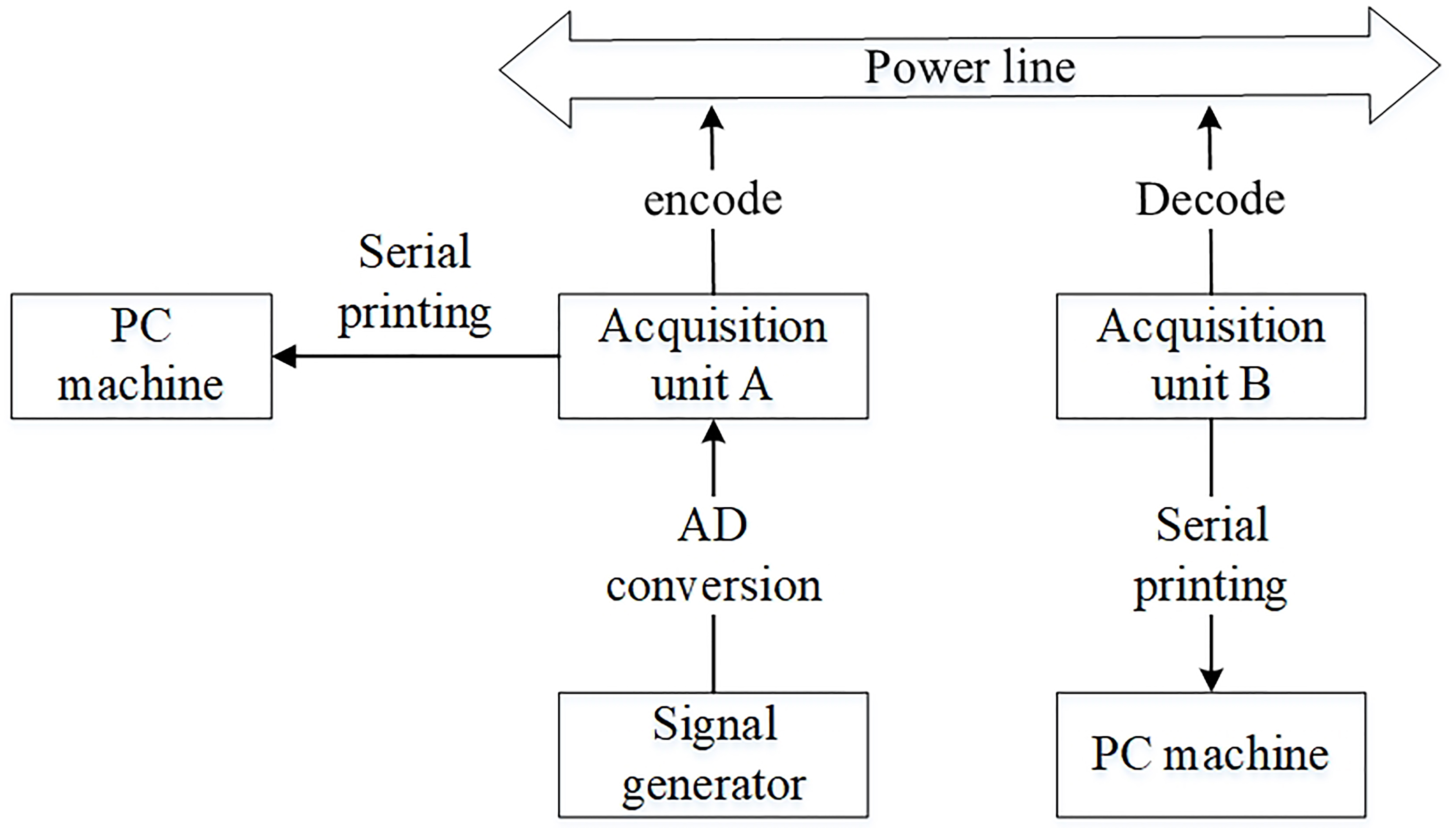
After establishing the test environment, the monitoring unit can monitor the signal generated by the signal generator in real time and the PC machine can check the monitoring information constantly. Taking the cable voltage of sending end as an example, this research compares and analyzes the data collected from AD conversion of unit A (real value) and the data received by the B unit (observed value), as shown in Fig. 8.
The comparison of real value and observed value.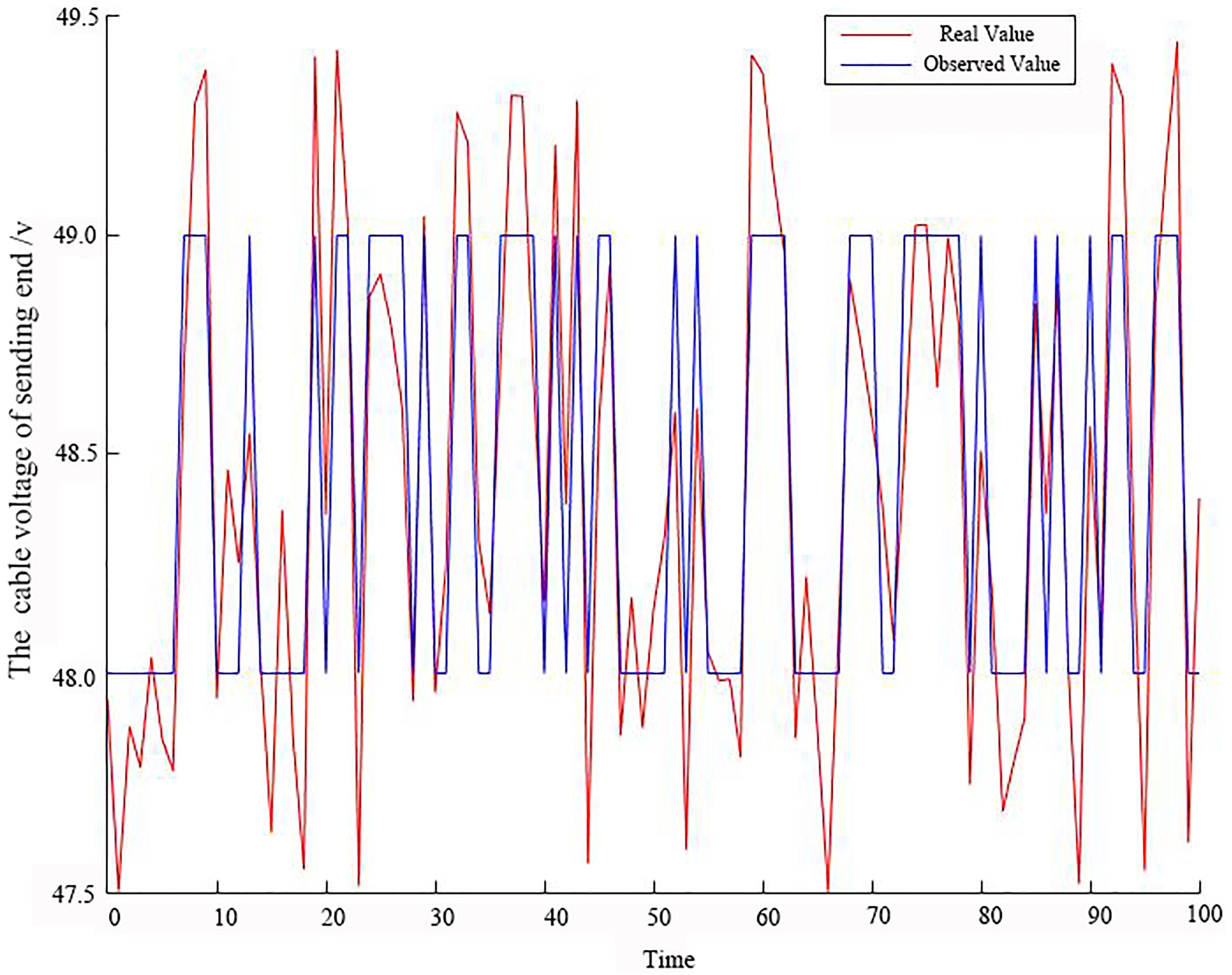
Since the cable voltage of sending end encoding occupies 3 bits, so the outdoor information monitoring unit can only monitor the 8 V range of data. Hence the unit B acquired data accuracy is lower than the real value, but it still meets the basic demand.
In the same way, other parameters of the track circuit are simulated, which the mean value of the real values and observed values is presented for a period, as shown in Table 1.
Experiment record
The results show that the voltage, current and other parameters received by the PC machine are consistent with the signal of the signal generator. Therefore, the outdoor information monitoring unit can realize the whole process of information acquisition, encoding and uploading, and its functional characteristics have been verified in the test experiment.
Based on power line carrier communication technology, the research designs a program oriented ZPW-2000 outdoor track circuit, which can solve the practical difficulties of electrical maintenance and ease the pressure of equipment management department. According to the information collected by the monitoring unit, we can fully grasp the real-time application status of track circuit timely, and find the key points and important parameters of the equipment abnormalities, and formulate relevant maintenance operation and inspection plan. Ultimately, this monitoring system can improve the capacity of monitoring analysis and fault diagnosis of railway signal outdoor equipment, as well as greatly reduce the labor and time cost of maintenance work.
Firstly, this research elaborates that the power line carrier communication technology is suitable for railway signal outdoor information monitoring. Secondly, according to the analyzing the characteristics of power line carrier communication, we know that its transmission rate is low, and it is easy to be affected by noise and other unfavorable factors, so this study presents a specific encoding method and transmission mode of monitoring information. Thirdly, the design program of outdoor equipment information monitoring unit based on power line carrier technology is proposed, and it realizes the function of acquisition, storage and upload of the information of outdoor signal equipment. Finally, this research tests and verifies this monitoring system in the ZPW-2000 track circuit, and the results are satisfactory. Therefore, this railway signal outdoor information monitoring technology can provide timely first-hand outdoor information, so it is significant for railway signal outdoor equipment to diagnose and detect the faults accurately, as well as eliminate the hazards timely.
Footnotes
Acknowledgments
The authors thank to ShandongJianzhu University Grant commission and College of Surveying and Geo-Informatics for financial support. We also acknowledge Key Laboratory of Road and Traffic Engineering of Ministry of Education, Tongji University for providing necessary research facilities. The authors are grateful for the reviewer of initial drafts for their helpful comments and suggestions.