
Abstract
The current wave form of active boost PFC is simulated in time domain and frequency domain. With the voltage of 220 v, the inductance of 15 mH, the capacitance of 5040
Introduction
The harmonic pollution becomes more and more dangerous. Most equipments preamp adopts PFC, which makes power factor close to 1. The PFC includes passive PFC and active PFC. The time domain and frequency domain of PFC are analyzed with the OFF phase angle and capacitor [1, 2, 3, 4, 5, 6, 7, 8, 9, 10, 11, 12, 13, 14, 15, 16, 17, 18, 19, 20, 21]. The PFC is designed.
The simulation of boost PFC current
The transistor is shut off when the voltage is zero. The voltage is sin
The transistor is on or off. The power of
The current of
Where
The waveform of current and voltage of capacitor is shown in Fig. 1 the parameters are as followed: the voltage of power is 230 V and the frequency of power is 50 Hz; the inductance
PFC scheme.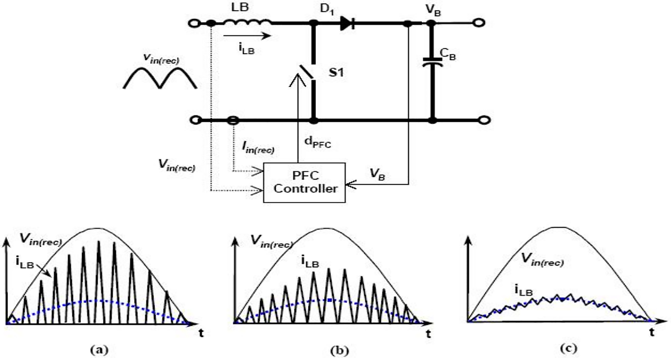
The higher harmonic of current is derived from Fourier transform.
Current and voltage.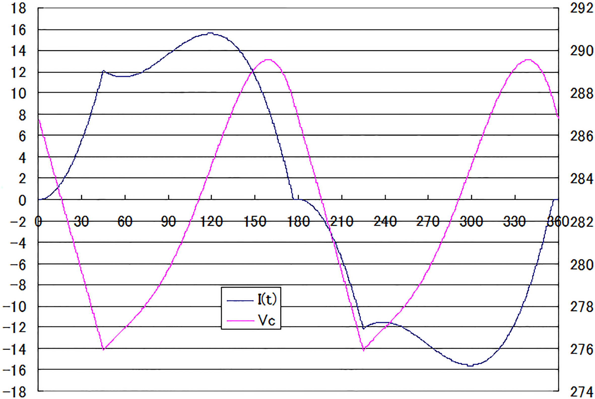
Current harmonic.
IEC61000-3-2.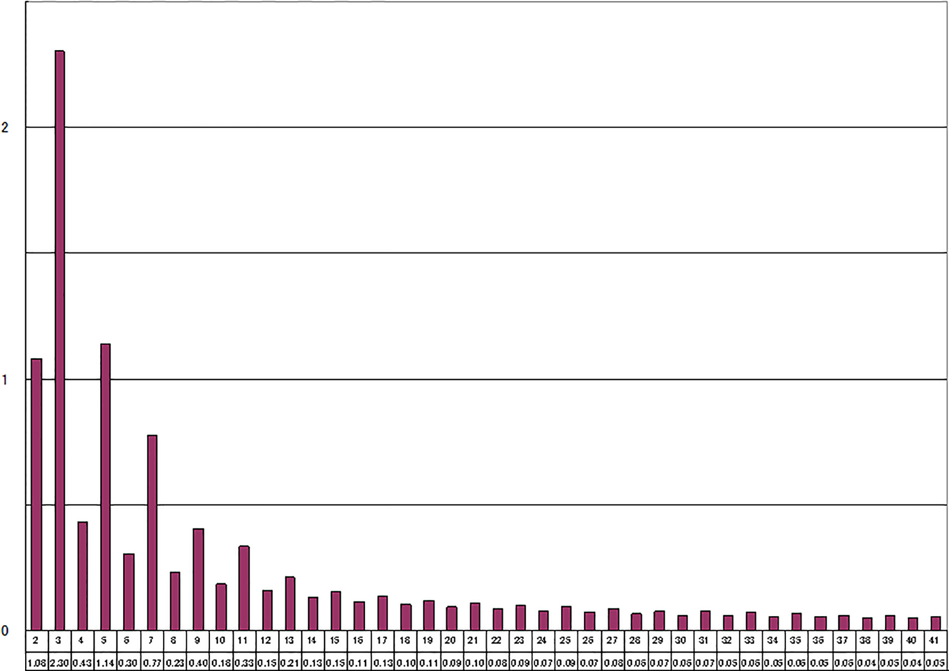
The integral mean of current is shown in Fig. 2. The current harmonic is shown in Fig. 3 while the upper limit of harmonic is shown in Fig. 4. The most component is fundamental wave. There are fewer ripples.
The integral mean of current in Fig. 2 is the current 11.1 A. The voltage 230 Vrms is obtained Also. The apparent power is 2553 VA while the load power is 2500 W. The integrated power factor (cos
Sine component of fundamental wave is
The power factor caused by waveform distortion is:
Harmonic at 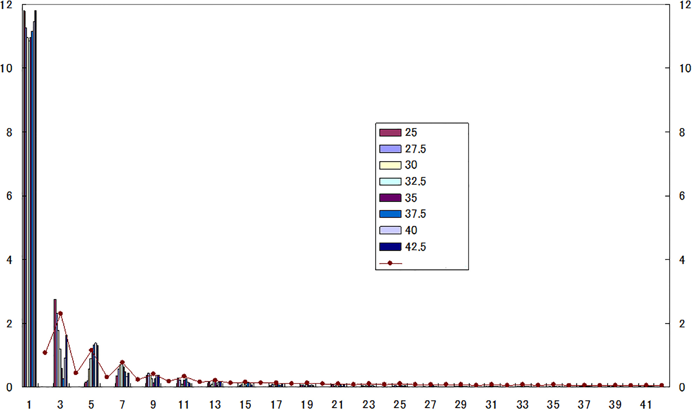
The waveform distortion is:
The integrated power factor is mainly the result of cos
Harmonic at 
Distortion.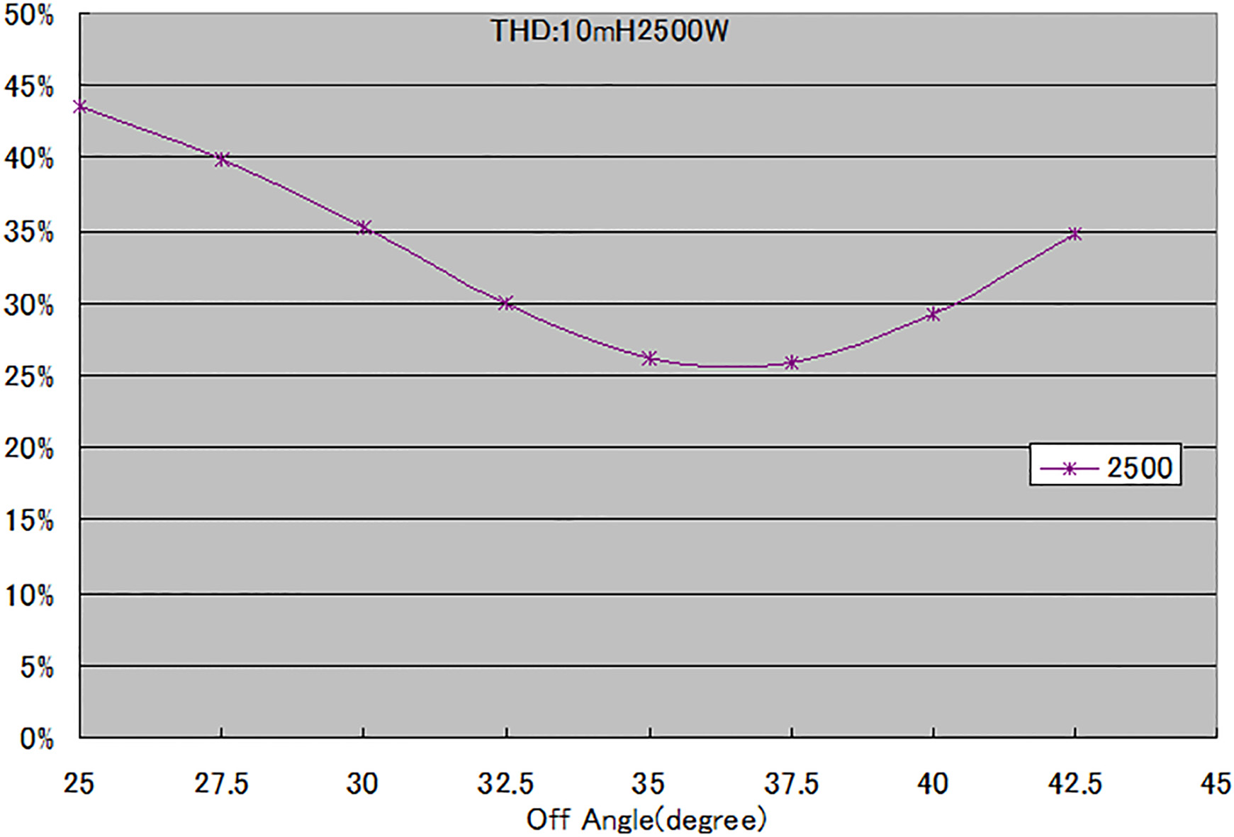
The integrated power factor can ignore the waveform distortion if the inverter capacitor doesn’t exist. If the inverters become intensive, cos
The upper limit of harmonic is by reference to Fig. 4. The sum from 2nd to 41st harmonic current is 3.04 A.
The distortion is supposed to be zero; the power factor is to be 100%. The current is 10.89 Arms. Therefore the lower limit of power factor 96% and the upper limit of distortion is 27%.
The higher harmonic of current is shown in Figs 6 and 7 when
The ‘off’ time can’t match the condition (3rd and 5th harmonic) when
In ‘off’ time the distortion with inductance of 15 mH, power factor of fundamental wave and integrated power factor are shown in following Fig. 7:
The OFF phase angle is 37 at least distortion in Fig. 7. The OFF phase angle is 32.5 at the maximum fundamental power factor in Fig. 8. The OFF phase angle is 34 at maximum integrated power factor in Fig. 9. If the main requirement is by reference to IEC61000-3-2, the phase corresponding to least distortion is chosen, the phase corresponding to maximum integrated power factor is chosen.
Fundamental wave power factor.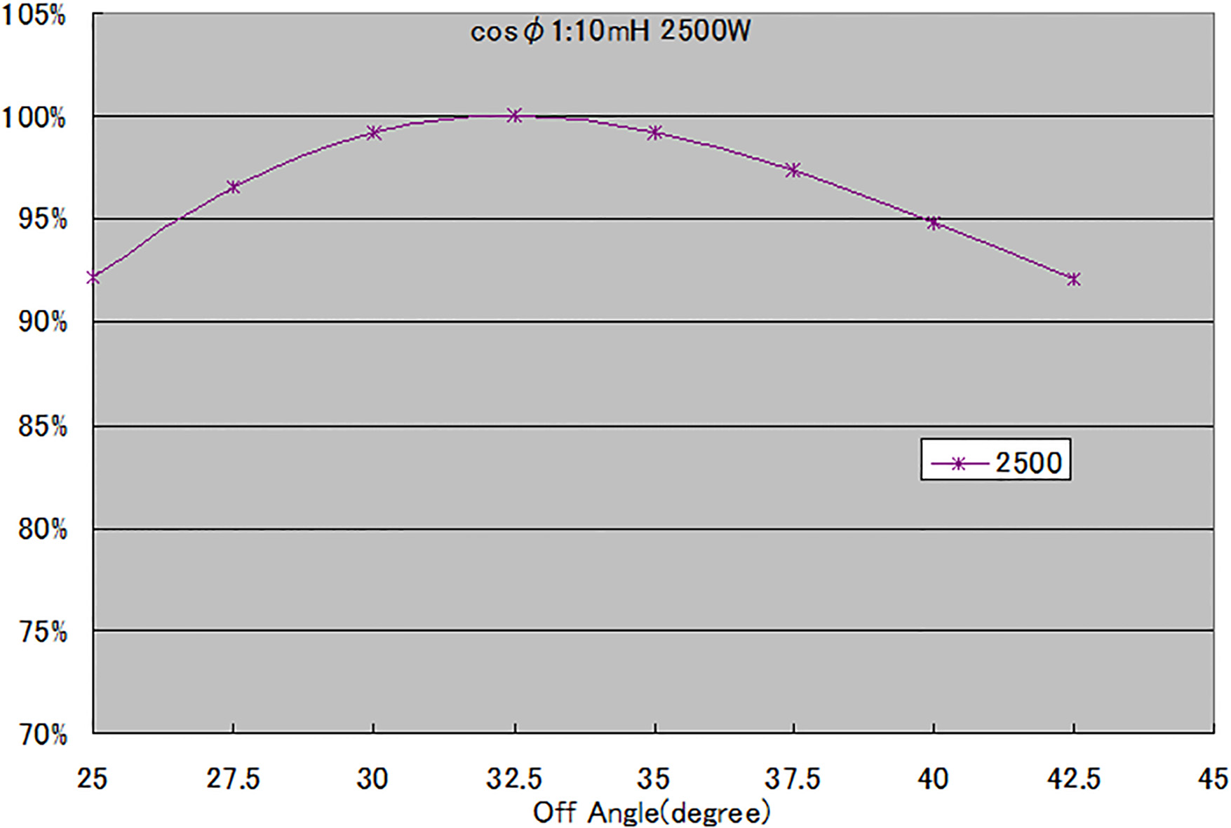
Integrated power factor.
The requirement is as follows: the voltage is 90 V
Current value
Current value

Zero crossing detection.
M On/Off Implementation.
Input capacitor. The rectifier is followed by a CBB which inhibits input voltage ripple and reduce differential mode interference.
Where Voltage value

Current waveform.
Voltage waveform.
Power factor under different inductance.
Power factor under different capacitance.
Inductance. The following equation is used in order to calculate the inductance value L of ac reactor. It is obtained from ripple current by reactor located between AC input and DC link voltage
Where:
Experiment.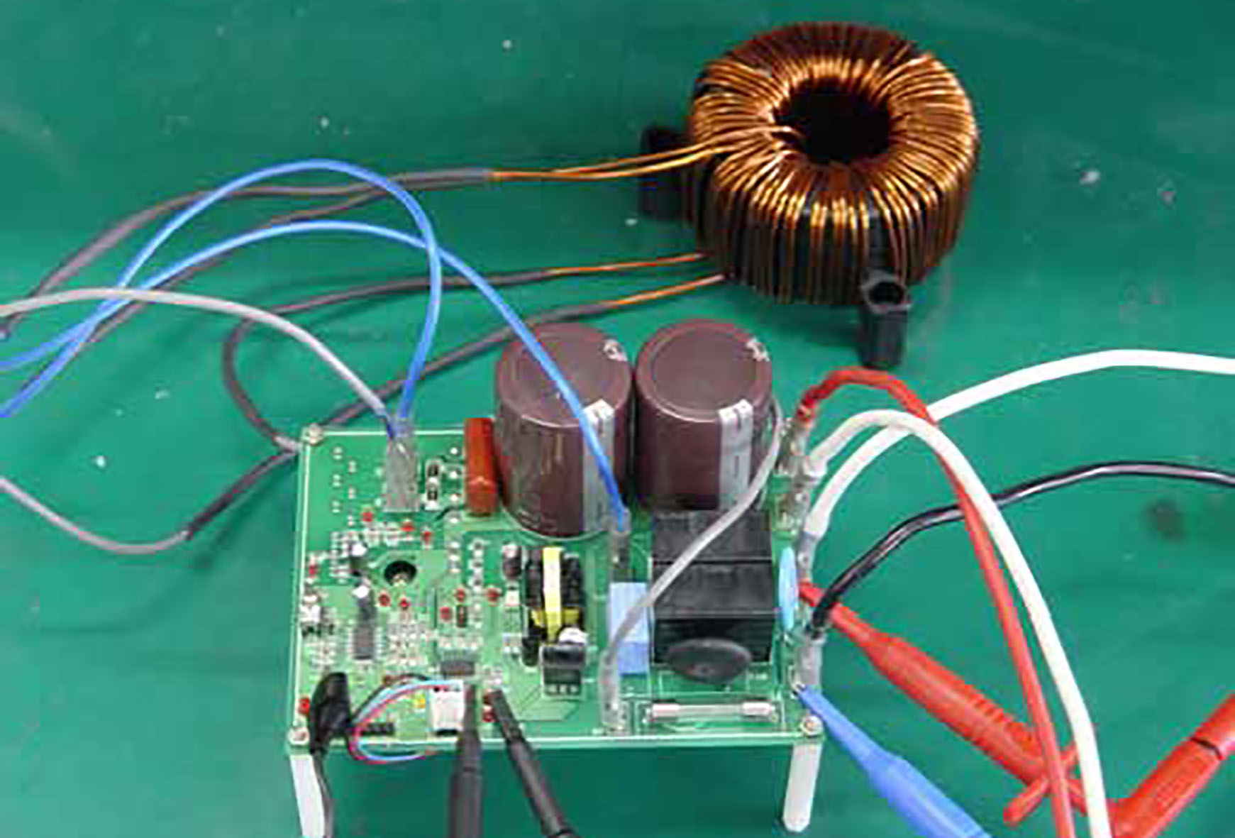
Switching tube and power diode. Due to the symmetry of topology one circuit is discussed. When switching tube is on, the tube current is inductance current, the diode is off and the reverse voltage is output
The switching tube is here SPW20N60S5, which normal voltage VDS
Calculation of wire turn number
The coupled inductor as PFC reactor is utilized. The turn number of each wire is calculated using the following equation:
Zero crossing detection of utility voltage is shown in Fig. 10:
Firstly Bidirectional photocoupler outputs short pulse. Then DSP generates external interrupt at the falling edge of pulse train.
PWM on/off Implementation
Power factor
Topology.
Current wave.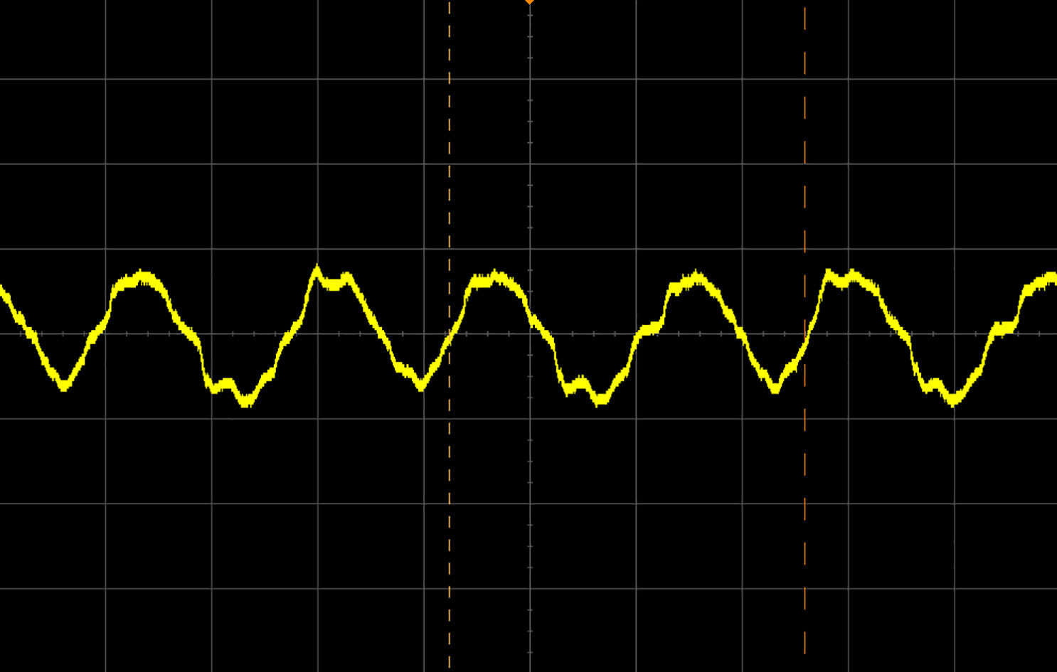
Power factor.
Zero Crossing Detection of Utility Voltage is followed by PWM On shift from PWM Off in Fig. 11. When PWM rises to PWM reference, the PWM is off.
The PFC circuit is utilized to inverter air conditioner. The Figs 12–15 shows current voltage waveform and power factor. The Tables 1–3 are the specific values of current voltage waveform and power factor under different conditions. The Fig. 16 is the PFC experimental situation while Fig. 17 shows topology. When DC-link voltage exceeds maximum (minimum) allowable value, Off Angle should be decreased (increased). The circuit utilizes two-phase interleaved average Current-Mode Control (CCM). Ripple current cancellation allows smaller input and output filter components. Magnitude and rate is adjustable to help pass stringent tests. Multiple features add many levels of protection, safety and reliability. Only On-time current is sensed in MOSFET drain. OFF-time current is synthesized. (Diode sensing is not needed). The Fig. 18 is the current waveform. The current sampling device is 1:1000 times magnetic balanced hall current sensor whose transfer ratio 1 A/300 mV. External sampling resistance is 300
Footnotes
Acknowledgments
This work is partially supported by Natural Science Foundation of Guangdong Province GUANGDONG (2017A030313291), (2018A030313418), (2015A030313797) and Guangdong Science and Technology Project (2016A040403028, 2017A010102020).
Conflict of interest
The authors declared no conflicts of interest.