
Abstract
This paper proposes a method for compensation of sampling offset for orthogonal frequency division multiplexing (OFDM) used in wireless local area networks (WLAN). Sampling offset is a typical transmission interference used in OFDM systems that introduce large error when synchronized data is demodulated. In this regard, an appropriate offset compensation method with a simple structure can be adopted to mitigate the impacts of sampling offset by using cross-correlation and early-late gate compensation methods for OFDM receivers instead of conventional methods that use algorithms with analog and mixed mode loops implementations. When bit error rate (BER) is at 10
Keywords
Introduction
OFDM is widely accepted and used in the wireless local area networks (WLANs) because it has high spectral efficiency and offers excellent robustness against inter symbol interference (ISI) [1]. Sampling offset is a very sensitive factor affecting the performance of OFDM systems and is manifested in sampling frequency offset, sampling point offset and phase offset. To ensure the optimum performance of OFDM system, the use of high precision synchronization technology is of great importance. In terms of the synchronization problem of OFDM transmitter and receiver, there are usually two solutions, namely synchronous clock method and asynchronous clock method. The synchronous clock method means that the transmitter shares the same clock frequency with the receiver and stays the same as the receiver’s, but requires plenty of hardware resources and difficult to be implemented. On the other hand, asynchronous clock method means the clocks of both the transmitter and receiver are independent of each other [2]. In most cases, asynchronous clock method is adopted since its hardware implementation is relatively simpler that of the synchronous clock method. However, it will lead to sampling offset due to desynchronized clocks. To solve this problem, the receiver needs to sample the baseband data without generating sample offset before completing data demodulation.
In asynchronous receivers, several methods used to solve the sampling offset problem in OFDM system have been proposed in literatures. A joint acquisition algorithm for the carrier frequency offset (CFO) and sampling frequency offset (SFO) that is achieved by a maximum-likelihood (ML) estimator with closed form and low-complexity had been proposed. Unlike conventional maximum-likelihood (ML) methods, the proposed method does not require a two-dimensional exhaustive search [3]. A joint ML blind estimator with simplified closed form is presented that by employing a Fast Fourier Transform (FFT) for the duration of one symbol to greatly reduce the amount of calculation [4]. A GI2L model and its corresponding method based on the guard interval and two long symbols, by which SFO or CFO can be estimated and corrected, improved the BER performance [5]. A new method proposed used improved early-late gate to obtain symbol timing offset and least-square fitting method to estimate sampling clock offset and ensure sampling clock synchronization [6]. According to the references, the sampling offset is usually compensated in two ways. The first is estimating and then compensating the value of the error of the sampling offset. This method requires a large amount of calculation [7, 8], because it must have Fourier Transform (FT) and extraction of the pilot in frequency domain before it could calculate the value of sampling frequency offset and compensate it. The second, named blind estimation, compensates the sampling frequency offset without estimating the value [9, 10]. The sampling offset compensation steps in the literatures are as follows: first, estimating the sampling frequency offset, which is called error detection; second, getting the error value through the loop filter and interpolating the value; and finally, compensating sampling frequency offset. These steps are more complex and difficult to implement.
In this paper we proposes the use of OFDM symbol cyclic prefix sequence and tail symbol sequence by correlation, finding the maximum correlation values, and adjusting the FFT window position to compensate the sampling offset [11, 12]. This paper will take IEEE802.11ac protocol as an example to illustrate the performance of the algorithm. The main content and the structure of the thesis are described as follows. Section 1 gives a brief introduction about sampling offset and relevant compensation methods. Section 2 presents the frame structure and OFDM system model. Section 3 describes the timing loop in compensation methods. Finally, Sections 4 and 5 depict the analysis of simulation results and conclusions respectively.
IEEE802.11ac packet formation and OFDM system model
IEEE802.11ac
The IEEE802.11ac is a WLAN standard on the 5 GHz band that was created by the IEEE Standards Committee and based on previous standards. The algorithm design of the transmitter and receiver needs to meet the IEEE802.11ac specification requirement of 1 Gbit/s maximum multi-station throughput. The protocol gives the structure of the data frame (Fig. 1) with the transmitter’s variable factor being smaller than that of the receiver. The emphasis of algorithm design is focused on the receiver [13].
802.11ac packet structure diagram. The structure of frame is given by the IEEE802.11ac protocol.
In IEEE802.11ac, an OFDM data symbol is made up of a symbol and a cyclic prefix (guard interval), which is formulated by the protocol. The cyclic prefix is divided into two kinds: long cyclic prefix sequence and short cyclic prefix sequence. The long cyclic prefix and the short cyclic prefix are 1/4 and 1/8 of the length of OFDM data symbol respectively. In this paper, an OFDM data symbol is consisted of a short cyclic prefix and a symbol data [14]. The cyclic prefix is the last quarter (normal CP) or the last eighth (short CP) of each OFDM symbol. These two kinds are stipulated in 802.11ac protocol.
In the OFDM system, the transmitted and received signals can be represented as a simple equation in the frequency domain. The single input and single output (SISO) model can be presented as Eq. (1).
In the above equation,
The receiver is considered to be ideally synchronous in the above system model above. In fact, carrier frequency offset and sampling frequency offset are introduced at the receiver due to the unstable or mismatched oscillation frequency between the receiver and transmitter, or even the Doppler frequency shift of channel. In the following analysis and calculation,
where, the sampling duration is denoted by
Here
when
Here
In the equation above, part one is caused by the SFO and the CFO, and part two is fully effected by the SFO. In this paper, we mainly correct sampling offset through loop, assuming there is no CFO. So the system model is denoted as Eq. (6).
Sampling offset compensation method
Early-late gate sampling offset compensation method mainly uses OFDM symbol structure to extracts the tail data of OFDM symbol and cross-correlate with cyclic prefix in order to find the maximum value point [17, 18] and use it to move the FFT window position to compensate the sampling offset. The schematic diagram of sampling offset compensation method is described in four parts as shown below (Fig. 2). 1) An FFT window controls the starting position of the FFT data. 2) A delay unit (retarder) is used to extract the data from the tail of a symbol. 3) A sampling correlated accumulator is used for down-sampling the different baseband sequences. It also can extracts the tail data and cyclic prefix for accumulation and calculation. 4) An early-late gate comparator uses the principle of the early delay gate to determine the maximum point in the correlator and sends it to the FFT window through loop feedback. Finally, the compensated data is fed to FFT module [19]. While this method is just an algorithm, there is no complicated hardware involved. It can be considered as a low complexity design.
Schematic diagram of sampling offset compensation method. Sampling offset compensation module is mainly composed of FFT window, Retarder, Sampling correlation accumulator and early-late gate comparator.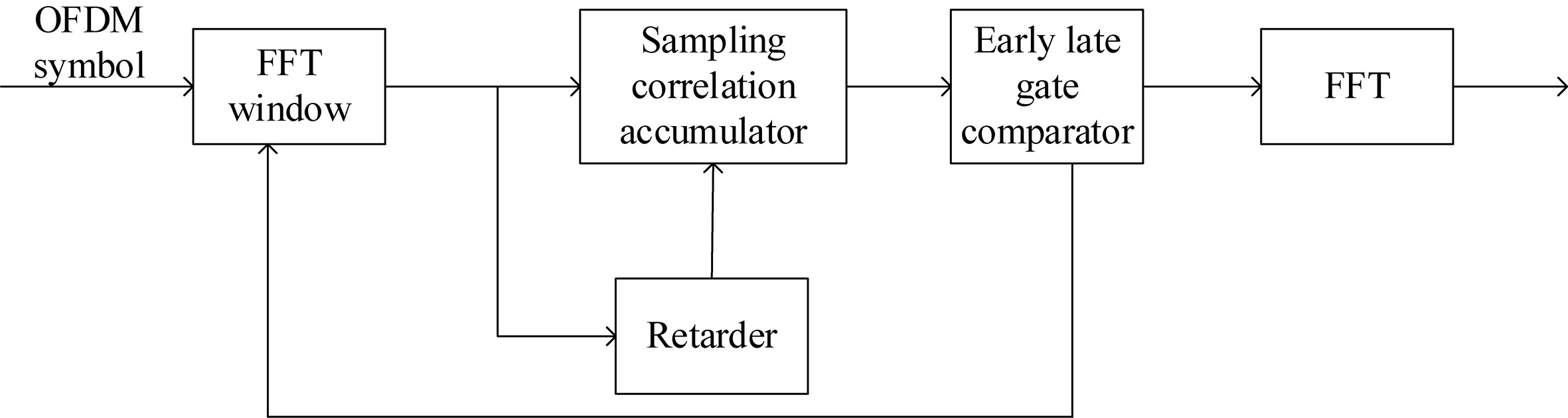
FFT window
The FFT window is controlled by two parameters: the starting point and the length of the FFT window. The starting position is used to identify the specific position where each OFDM symbol starts and to achieve it in place. FFT window length is determined by algorithm, usually half the length of the OFDM symbol or one length of symbol. This paper chose one length of the symbol.
Retarder
The retarder delays the received data and obtains the tail data of one OFDM symbol, and sends it to the sampling correlation accumulator as shown by Eq. (7).
The equation above assumes
Sampling correlation accumulator is mainly composed of two parts, the down-sampling data and the correlated accumulation. The down-sampling data part is stored and the correlated accumulation part calculates the result.
The starting position of the FFT window is determined once synchronization has been completed. The initial position of the OFDM symbol is accurately received that described as Eq. (8).
where
Early-late gate comparators are used to compare the magnitude of the cross correlation values of the sampled sequences under different sampling starting points. By sampling the correlation accumulator
where
The advantage of the proposed algorithm is that it does not need to know the specific value of the sampling offset, and the sampling offset can be directly compensated by the receiver loop, which has high practical value. This paper uses data of the 20 M baseband, 4 times up sampling rate, 64QAM constellation, 100 frames, and 80 OFDM symbols to simulate the performance of the system. Assuming that the system only has the effects of sampling offset, the constellation would appear as shown.
Receiver constellation under ideal conditions. It is the ideal 64QAM constellation diagram.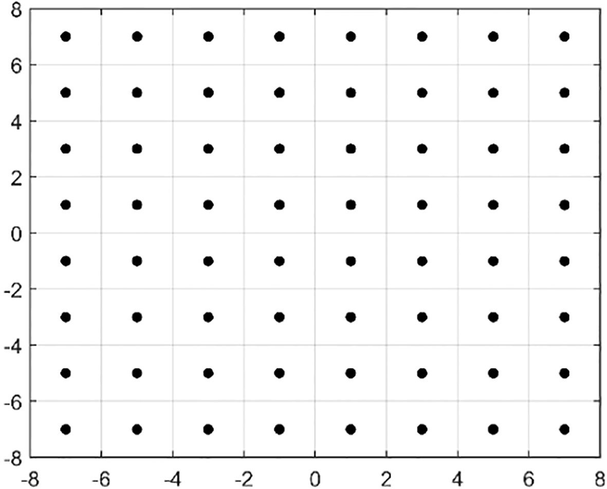
The above figure is the ideal 64QAM constellation diagram (Fig. 3). Every point in the constellation denotes data point in 20 MHz baseband scenario. There are 52 data points in one OFDM symbol, 4 effective pilot points, and 8 protection pilot points. Among them, the effective pilot points are (1, 0), (1, 0), (1, 0), and (
The receiver constellation with 15 PPM sampling offset. When the sampling offset is less than 15 PPM, the data can still be properly demodulated.
From the simulation results we can see that the sampling tolerance of the system is 15 parts per million (PPM). When the sampling offset is less than 15 PPM, which has little effect on the system, and there are still no errors in the data demodulation (Fig. 4).
The receiver constellation with 80 PPM and 
If the receiver only has sample offset and no sampling offset compensation module in both 80 PPM (Fig. 5a) and
The constellation diagram and module verification diagram of the 0 PPM sampling offset compensation module. a. Constellation diagram. b. Module verification diagram of compensation.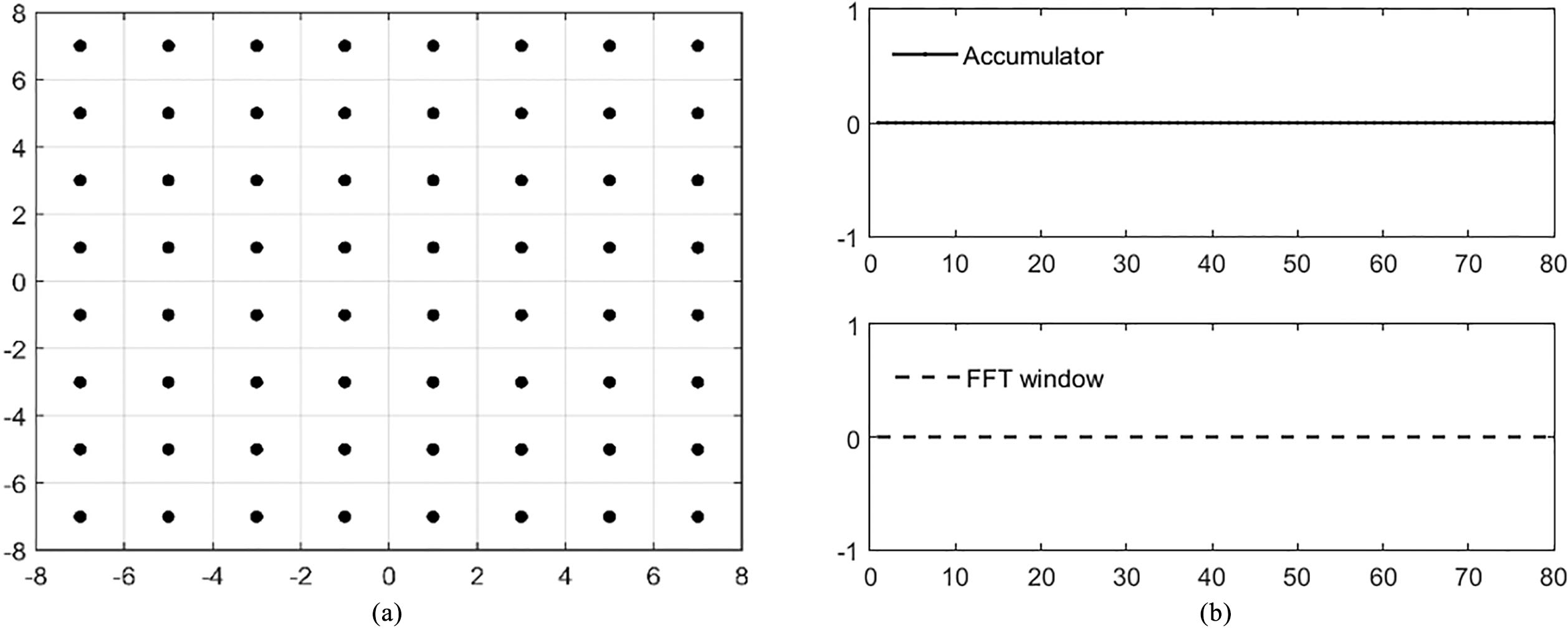
In the absence of sampling offset (Fig. 6), the constellation is similar to the ideal constellation diagram (Fig. 6a), even if the sampling offset compensation module is added, the early-late gate accumulator and the FFT window will not be activated (Fig. 6b), thus having no influence on the system performance in high SNR situation.
The constellation diagram and module verification diagram of the 15 PPM sampling offset compensation module. a. Constellation diagram. b. Module verification diagram of compensation.
If the system added a 15 PPM offset after the early-late gate accumulator has started but did not reach the threshold of the early-late gate, the FFT window start position would change (Fig. 7b). The compensation module can compensate the remaining sample offset below 15 PPM (Fig. 7a). According to the verification results of Fig. 4 where the 15 PPM sampling offset is within the tolerance of the system, the data can be accurately demodulated (Fig. 7).
The constellation diagram and module verification diagram of the 80 PPM sampling offset compensation module. a. Constellation diagram. b. Module verification diagram of compensation.
By comparing Figs 8 and 5, it is shown that after adding the sampling offset compensation module, the effects of 80 PPM sampling offset on the system can be corrected and the residual sampling offset can be reduced to below the tolerance limit to ensure the data can be demodulated correctly (Fig. 8a). In this state, sampling offset triggers the early-late gate accumulator. When the accumulated value becomes larger than the threshold value, the FFT window shifts one point (Fig. 8b), then the early-late gate accumulator is reset to 0. This process repeats itself and compensate the effects of sampling offset.
The constellation diagram and module verification diagram of the 
As shown in the constellation diagram and module verification diagram of the
Comparison of BER performance with 80 PPM sampling offset.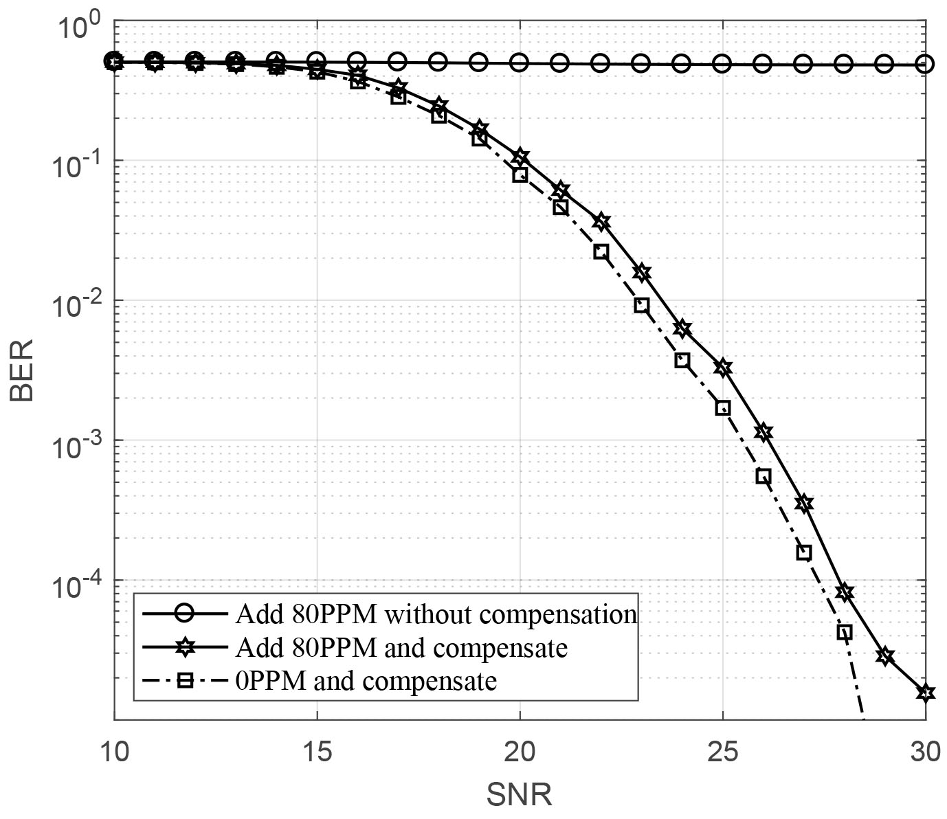
From the simulation results in the comparison of BER performance with 0 PPM/80 PPM sampling offset (Fig. 10), it can be seen that in the 80 PPM curve without sampling offset compensation, BER is a straight line and it does not converge, meaning the normal transmission process is not being carried out. By comparing the 0 PPM and 80 PPM compensation curve, it was shown that adding sampling offset compensation algorithm, the SNR of system decreased by 1 dB at 10
This paper proposes a sampling offset compensation method employing cross-correlation and early-late gate for OFDM receiver that effectively overcome the influence of sampling offset with low complexity of hardware in WLAN applications.
When BER is at 10
Footnotes
Acknowledgments
The authors acknowledge the financial support of the Key Projects of R&D and Achievement Transformation in Qinghai Province [nos.2018-NN-151 and 2019-GX-170], the National Natural Science Foundation of China [nos. 61761040 and 61771363], the ChunHui Project of Education Ministry [Z2016108].