
Abstract
Currently, the performance of the conventional airport navigation lighting system can’t meet the functional requirements of an airport under combat readiness or emergency state. A new type of airport navigation lighting system in mobile wireless ad hoc network is proposed in this paper. The system consists of a monitoring center, a coordinator and a number of terminal nodes. It can be flexibly transferred, concealed in time, remotely controlled, quickly started and networked on demand. According to the functions and the distribution characteristics of the navigation luminaries in the airfields, the terminal nodes are grouped according to regions. The cluster heads are selected in each group according to the energy of nodes and the distribution distance between nodes. By comparing the advantages and the disadvantages between the Cluster-Tree protocol and the AODVjr protocol, an optimized routing algorithm is proposed. In order to reduce the number of hops of RREQ broadcast packets and prevent the invalid RREQ flooding, this algorithm adopts the neighbor table algorithm of ZigBee protocol and regional grouping method. The results of the simulations and the test of small-scale hardware show that this optimization algorithm can effectively reduce the number of routing hops, shorten the transmission delay, reduce the number of dead nodes and improve the success rate of data transmission.
Introduction
The airport navigation lighting system is a very important device for flight safety when an aircraft is taking off, landing or taxiing at night or in low visibility conditions [1]. Airport navigation lights are usually classified into different categories, including sequence flash lights, approach lights, runway edge lights, runway center line lights, taxiway guidance lights, etc. [2]. The distribution of airport navigation lights is shown in Fig. 1.
The distribution of airfield navigation lights.
At present, the airport navigation lighting system consists of a power supply, a constant current regulator, lighting cables, isolation transformers and halogen lamps [3], its structure is shown in Fig. 2. However, this structure has some obvious weaknesses. First, the navigation lighting system is connected by cables. Once this system is damaged due to war, disaster or other reasons, it can not be quickly removed or repaired. Secondly, with the development of satellites and precision guidance technology, existing airports are easily found because of their fixed location and obvious targets, so their survival probability is greatly reduced [4].
The structure of a navigation lighting system for permanent airfield.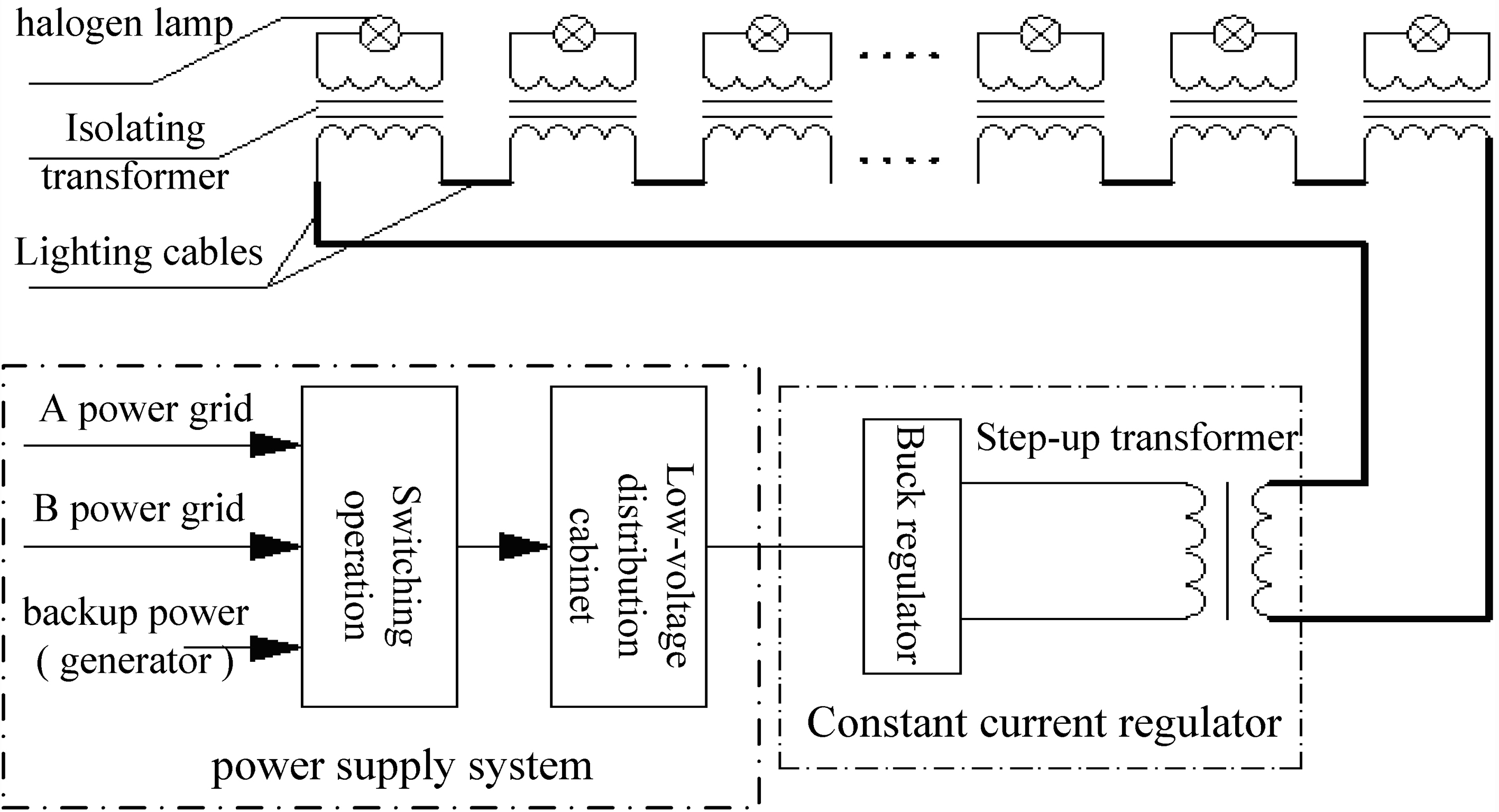
In the event of a war or major natural disaster, a freeway or an area of flat land may be used as a temporary emergency airport. Under such circumstances, the navigation lighting system in mobile wireless ad hoc network will play a very important role in meeting the emergency needs during wartime and disaster relief [5]. This is crucial for national security and the safety of people’s lives and property.
In recent years, with the development of LED technology, the power consumption of a single LED has been reduced by about 80%. Compared with the halogen lamp, if the airport navigation lighting system uses LED technology, the overall load of the system will be reduced by about 70% [6, 7].
Additionally, in recent years, short-range wireless communication technology has been widely used. Compared with traditional wired communication, it has the advantages of lower costs, wireless capability, fault diagnosis and flexible mobility. At present, short-range wireless communication technologies usually include ZigBee, Bluetooth, Irda (Infrared data association), UWB (Ultra Wide Band) and Wi-Fi (Wireless Fidelity) [8].
Compared with the characteristics of several other communication technologies, ZigBee has the following advantages [9]: (1) Low power consumption: the life of its node can be up to 6–12 months with ordinary battery power. (2) Higher reliability: it uses anti-collision mechanism to avoid competition, so the nodes can automatically network to ensure the reliability of information transmission. (3) Short delay: the data transmission time delay is short enough to meet the real-time control requirement. (4) Large network capacity: it supports up to 65000 network nodes. (5) High security: a three-level security encryption algorithm is provided to ensure data transmission security, plus its frequency band is located in the common 2.4 GHz band, which does not conflict with the frequency band of the existing wireless guidance equipment of the airfield.
In order to meet the requirements of a temporary emergency airfield, an airport navigation lighting system based on mobile wireless ad hoc network consists of a monitoring centre, a coordinator and a number of terminal nodes. Its structure is shown in Fig. 3.
The structure of the wireless navigational lighting system.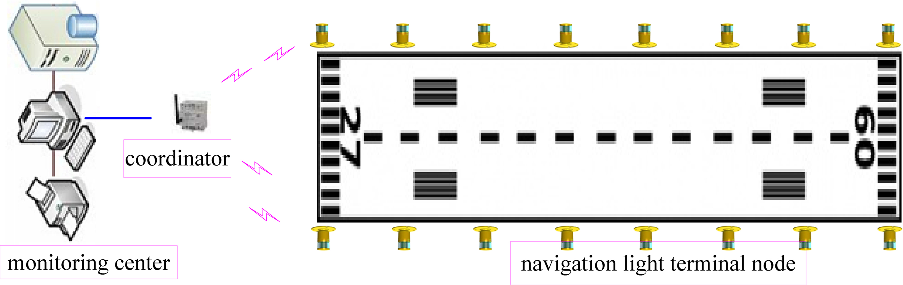
The monitoring centre communicates with the coordinator by data bus to complete the setting of relevant parameters. At the same time, it constantly polls the work status and the fault information of the terminal nodes. The guidance function for the aircraft can be achieved by the grouped control of the terminal nodes in same region and the combined control of the terminal nodes in different regions.
The coordinator communicates with the terminal node through the ZigBee wireless network. Meanwhile, the coordinator is responsible for establishing and maintaining the network, registering or deleting the terminal nodes, forwarding the commands of the monitoring centre and uploading information from the terminal nodes.
Each terminal node is a separate unit that can be flexibly moved and powered by a rechargeable battery. It uses an energy-efficient LED lamp to replace the halogen lamp. It has the advantages of being a small size, light weight and easy to carry to meet the requirements of concealment and operability in wartime. It uses the CC2530 as a controller. When it receives control commands from the coordinator, it analyses and executes the corresponding control tasks, including grouping end nodes, switching lights, and adjusting light levels. It can automatically detect the illumination level, lamp temperature, battery power and other information, and then upload the relevant data to the coordinator, so it can achieve on-line detection, location and alarm of node faults.
Design of wireless network topology for navigation lighting system
A ZigBee network usually has three topologies: star network, cluster network and mesh network [10]. The network topologies of ZigBee are shown in Fig. 4.
Network topology of ZigBee.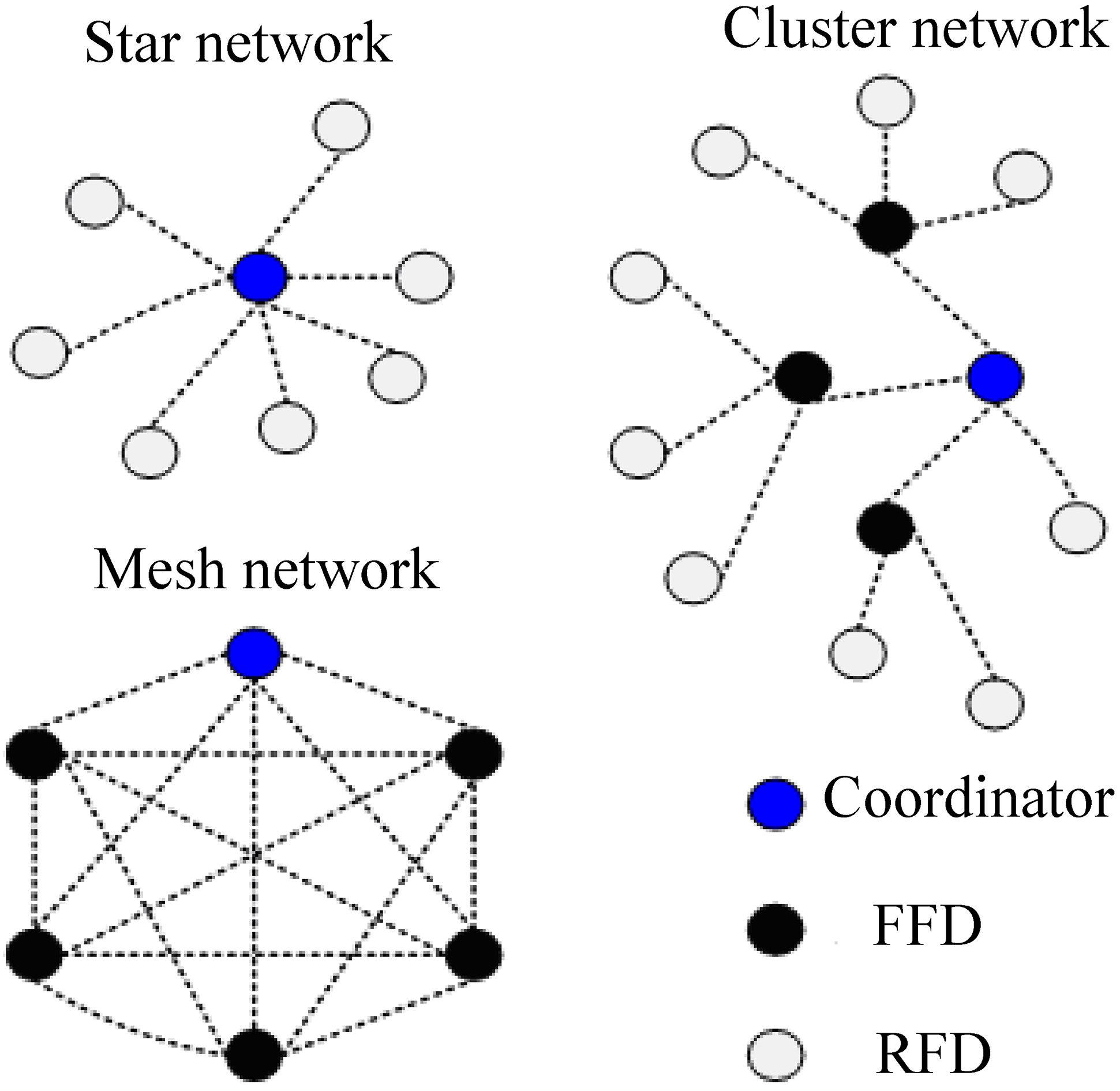
Star network: a star network has multiple terminal nodes, but only one coordinator. The coordinator is a full-function device (FFD), which is located in the center of the network and is responsible for the establishment and maintenance of the entire network. The terminal node is a reduced function device (RFD), which is distributed in the network coverage area and directly communicates with the coordinator. Star topology is usually used in places where there are fewer network nodes. Cluster network: in the cluster network, the relay node is generally FFD, the terminal node is generally RFD. Within the network coverage, the coordinator or the router node provides the terminal node with a synchronization information service. The router node is also under the control of the coordinator. The advantages of a clustered network lie in its large network coverage. However, with the expansion of the network size, the delay of information transmission increases correspondingly, which makes the control of information synchronization more complicated. Mesh network: a mesh network is a backbone network formed by multiple FFD, where one of the nodes is set as the coordinator. The edge node of the mesh network can also be a RFD, which is responsible for data collection. A mesh network can use multiple paths for data transmission. If a node breaks its path due to failure, the network can route the data to the subsequent nodes through other paths. Therefore, a mesh network has high reliability, because it can not only utilize the network “self-healing” function, but it also has a high degree of redundancy.
The mesh network can overcome the shortcomings of the poor scalability of the star network. Compared with the cluster tree network, its routing path is diversified, which can improve the robustness of the network. In order to ensure the robustness of the wireless navigation lighting system, all terminal nodes are configured as (FFDs). The network topology of the wireless navigation lighting system is shown in Fig. 5. If the routing function of node B is damaged when node A forwards data to node C by node B, the routing channel is blocked. However, each node has a routing function, node A can forward data to node C through other neighboring nodes. Therefore, the mesh network can utilize the self-healing function of the wireless navigation lighting system.
The topology of the navigation system.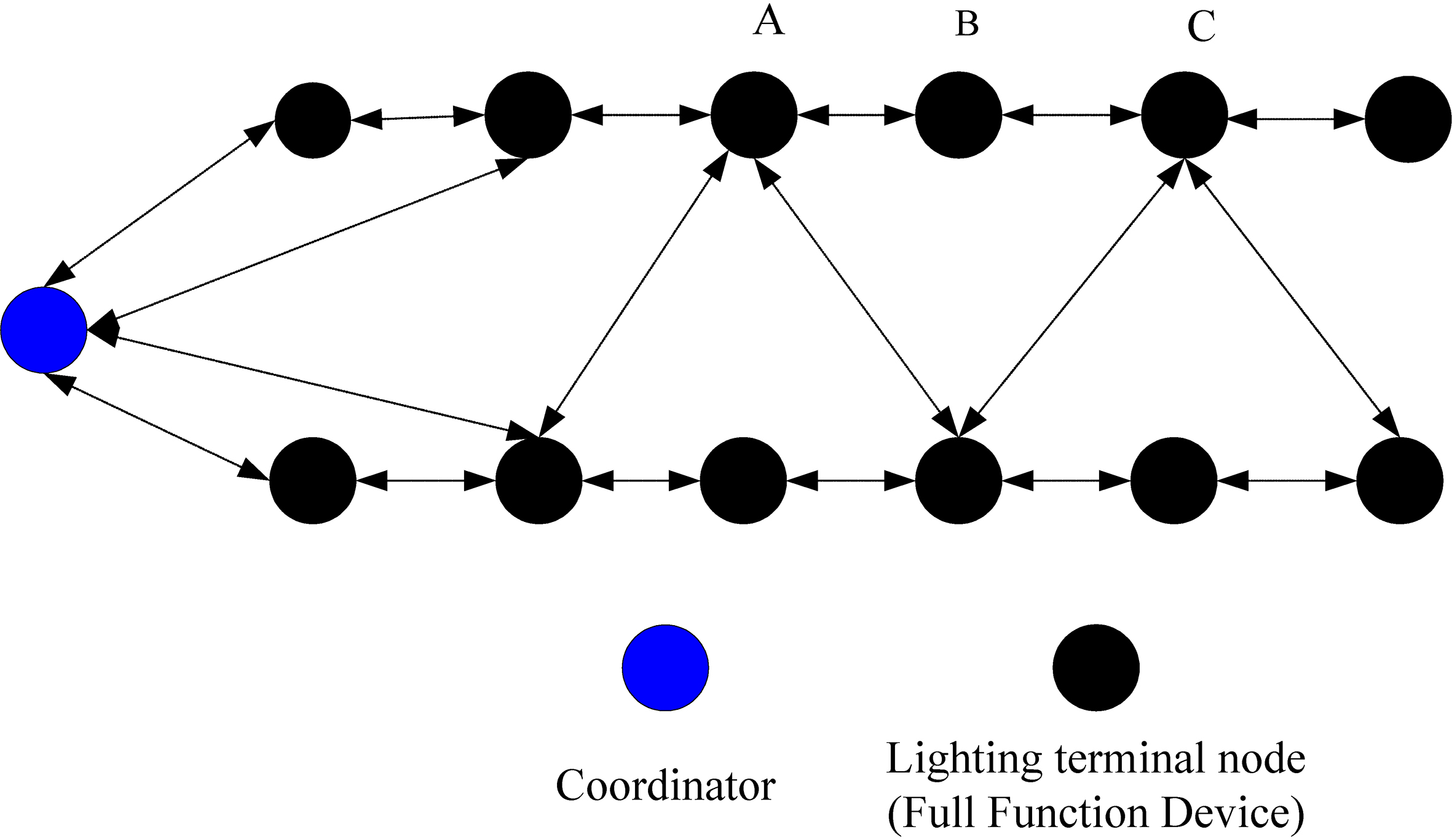
ZigBee’s mesh network usually uses traditional AODV (Ad hoc on-demand distance vector routing) to implement network routing. If there are many nodes in the network, the number of network packets will increase and the routing nodes will continue to broadcast messages, which will cause network congestion and delay and lead to a sharp decline in network performance.
The mesh network can carry out the self-healing function, but if the number of terminal nodes is very large, the real-time requirement is will be very poor. In order to prevent routing congestion and delay, it is necessary to have a suitable routing algorithm to achieve network control. According to the distribution characteristics of navigation lights, a neighbour routing algorithm is proposed to meet the control requirement of low delay and energy balance based on mobile wireless ad hoc network.
In a ZigBee network, each node has a network depth, which represents the minimum number of routing hops from this node to the coordinator. Suppose the maximum number of dependent nodes in each depth is
If the value of
If the node doesn’t have the routing function, its address is given by the Eq. (3), where an is the address of the child node, and
The cluster-tree routing algorithm is described as follows [12]: the network address is
If the address of node
According to the cluster-tree routing algorithm, the network address of each node in the network is preset, so it has no routing cost, and the delay of sending and receiving data is small. However, its data transmission path may not be optimized and the transmission efficiency is low. In particular, the routing nodes near the root node will transmit more packets, which cause an imbalance of network energy.
The AODVjr routing algorithm is an on-demand routing protocol. It supports unicast, multicast and broadcast. It can achieve a dynamic network between nodes. When the destination node is in the routing table, AODVjr doesn’t require routing discovery, it can send data directly. When the destination node isn’t in the routing table, the AODVjr needs to perform route discovery and establish a route transmission path, and then sends data, which increases the data delay. As the number of network nodes increases, there will be serious information blockages, conflicts and network storms. However, the AODVjr protocol can reduce power consumption, save network resources, and has a strong self-healing ability [13].
The flow chart of cluster head.
The CC2591 RF amplification chip is adopted to greatly increase the one-hop transmission distance of terminal nodes. Those nodes in a hop range are divided into a cluster. The node selected as the cluster head is responsible for collecting, packaging and forwarding data. The system chooses the cluster head according to the node density in a fixed region. The node density is determined by the signal strength RSSI of the node. First, it acquires the depth of the network and sets even-numbered nodes as candidate nodes of the cluster head. Second, when their signal strength is greater than the minimum value, the even-numbered nodes broadcast and decide whether to add node information to the neighbor table. Third, it compares the number of nodes in the neighbor table of each node and chooses the largest number of nodes as the cluster head. Fourth, the cluster head sends a broadcast message and maintains a list of cluster members after receiving a response from cluster members. Odd-numbered nodes are added to the cluster of their parent nodes. The flow chart of cluster head establishment is shown in Fig. 6.
The flow chart of the routing algorithm for navigation lighting system.
The flow chart of the the neighbor table routing algorithm.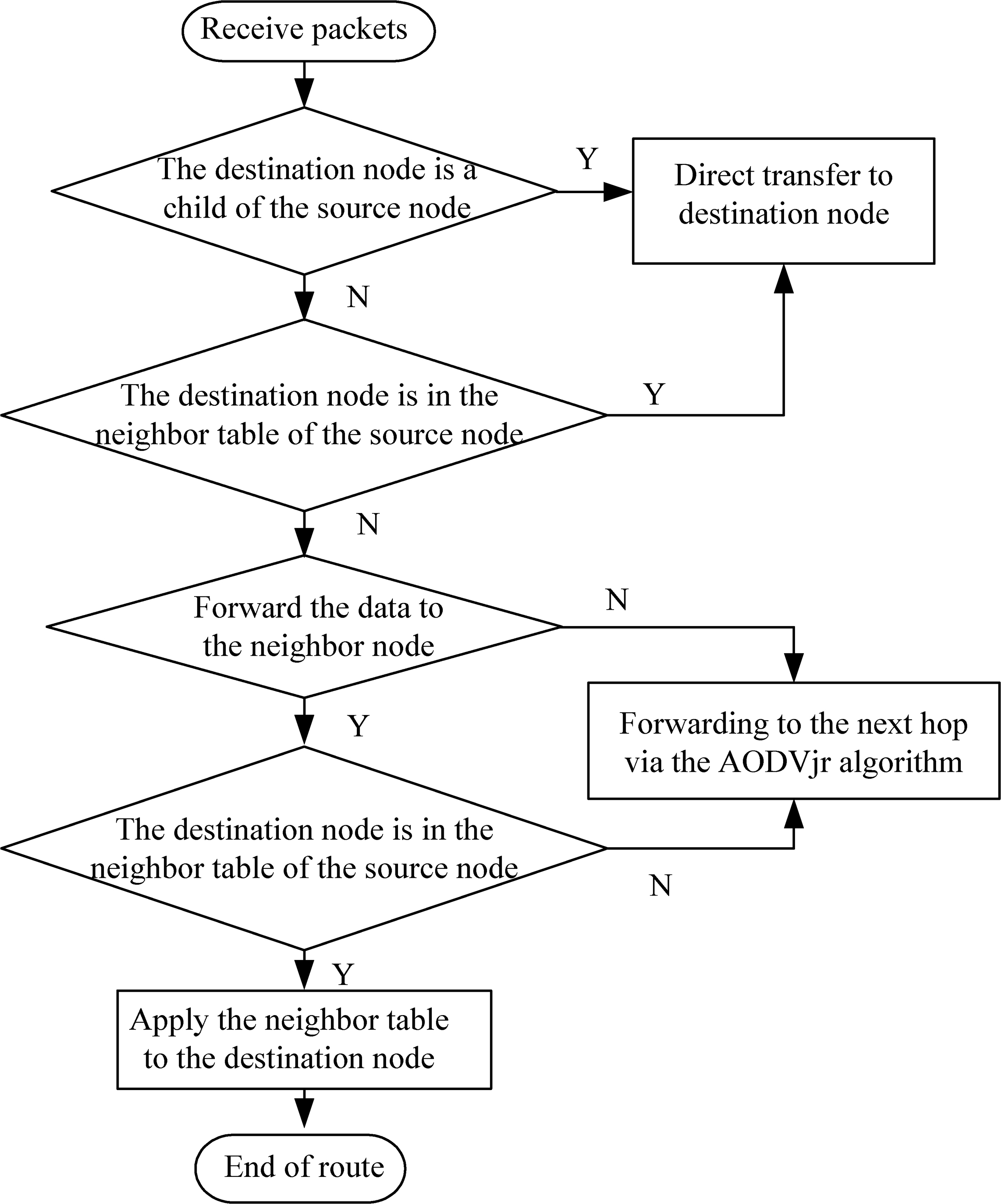
Packet delivery ratio.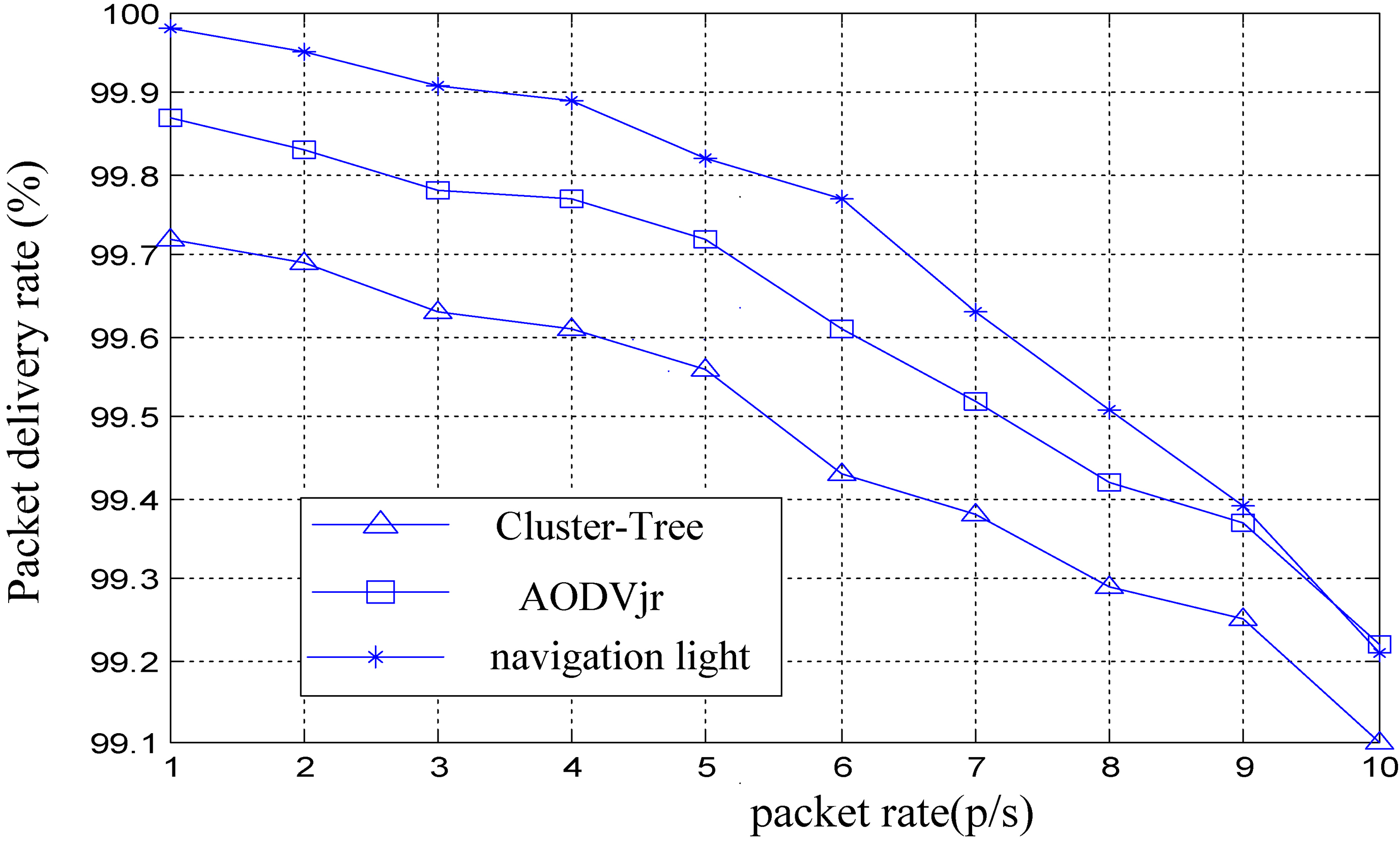
The average end-to-end delay.
The average number of hops.
The costs of routing control.
In the process of route forwarding, if the destination node and the source node are in the same cluster, the cluster tree routing algorithm will be used to send data, if the destination node is not within the one-hop routing range of the source node, route discovery will be performed to send data through the neighbor node information table of the source node. If route information can’t be forwarded to the destination node by the neighbor information of the source node, the AODVjr routing algorithm (a simplified version of the AODV protocol) will be used to discover a route until the data is forwarded successfully. The routing algorithm designed in this system can reduce the route hops, route cost and network transmission delay. The flowchart of the routing algorithm for navigation lighting system is shown in Fig. 7. In the neighbor table of the routing algorithm, it not only judges whether the destination node is in the neighbor table of the source node, but also uses the neighbor table of the neighbor node to route. The algorithm of the neighbor table is shown in Fig. 8.
NS2 (network simulator 2) is a network simulator, which is an object-oriented, programmable and visualized software. It can simulate a variety of scenarios (including DSR, AODV, DSDV, TORA), provide source code of MAC protocol (including 802.11, 802.15.4 and SMAC), and analogize the data flow of the transport layer [14]. The network simulation scene was set to 1000 times 600, the number of nodes was 10, the distance between nodes was 60 m, the maximum communication distance of the node was 100 m, the simulation time was 1000 s, the maximum depth L of the network was 5, and the maximum number of child nodes C was 4. In terms of the packet delivery rate, the average end-to-end delay, the average number of hops and the cost of routing control, the network performance of the AODVjr routing algorithm, the Cluster-Tree routing algorithm and the navigation light routing algorithm were compared and simulated under different CBR data flows. The results show that the navigation light routing algorithm has obvious advantages to satisfy the wireless network requirements.
The packet delivery rate is the value of the number of data packets received by the destination node divided by the number of data packets sent by the source node. The packet delivery rate is shown in Fig. 9. The average end-to-end delay is the value of the end-to-end delay of all received packets is divided by the number of all received packets. The average end-to-end delay is shown in Fig. 10. The average number of hops is the value of the number of times of all forwarded packets divided by the number of all received packets. The average number of hops is shown in Fig. 11. The cost of route control is the number of forwarded route messages during route discovery. The cost of route control is shown in Fig. 12.
System hardware functional structure
The terminal node consists of a control circuit and drive circuit. The CC2530F256 microprocessor is the core of the control circuit. It detects the radiator temperature of the LED lamp by the temperature sensor to achieve the over-temperature protection, detects the intensity of the LED light by the illumination sensor to realize the brightness adjustment, and detects the battery power to achieve charging reminder. It also expands the ZigBee transmission distance by the CC2591 RF, and achieves the LED lamp drive control by the PWM regulator, voltage detection and filament status detection. The hardware structure of a terminal node is shown in Fig. 13. The coordinator is the gateway device of the ZigBee, which is the connection channel between the terminal nodes and the monitoring center. The hardware structure of the coordinator is shown in Fig. 14.
The hardware structure of terminal node.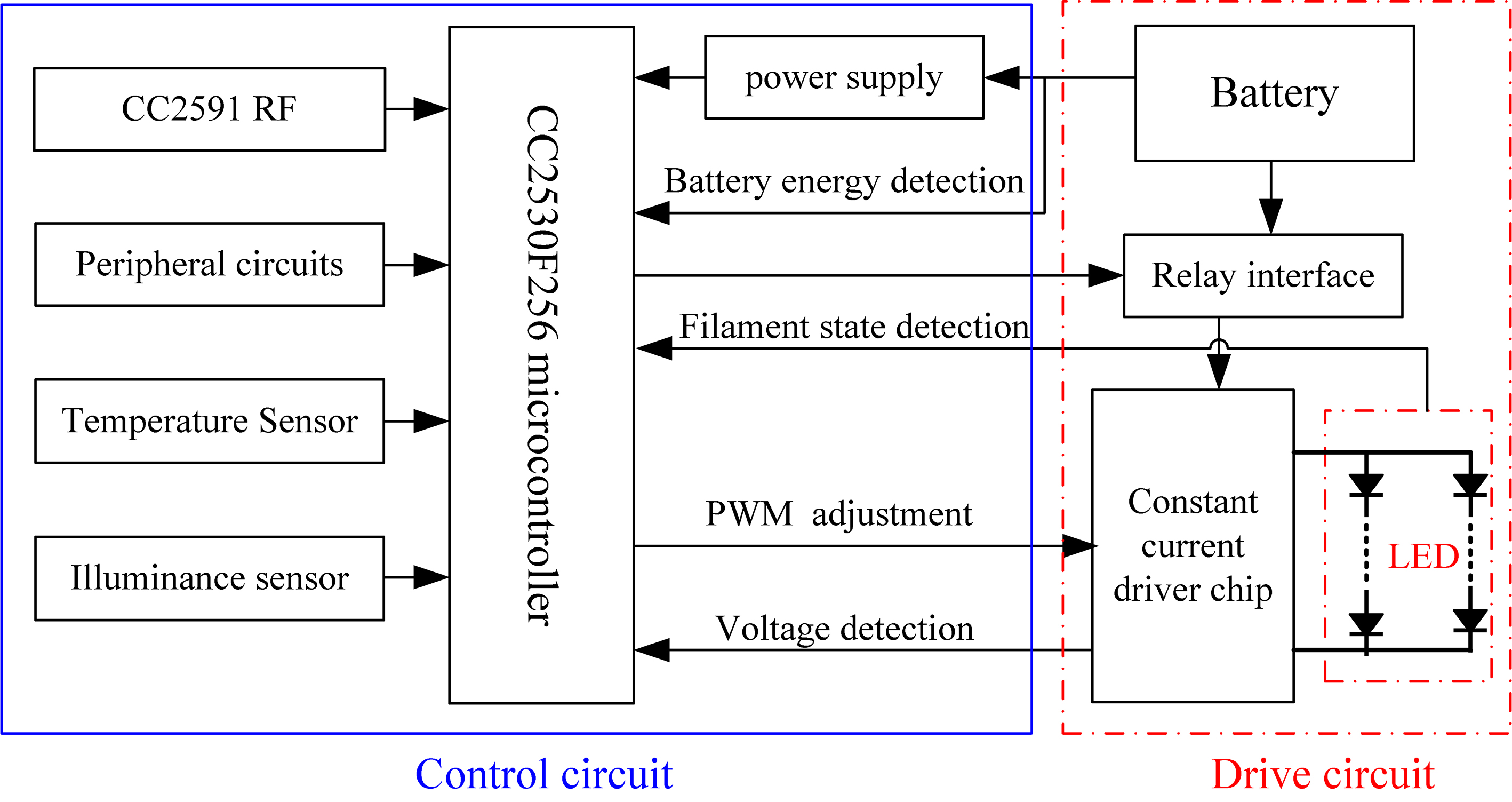
The hardware structure of the coordinator.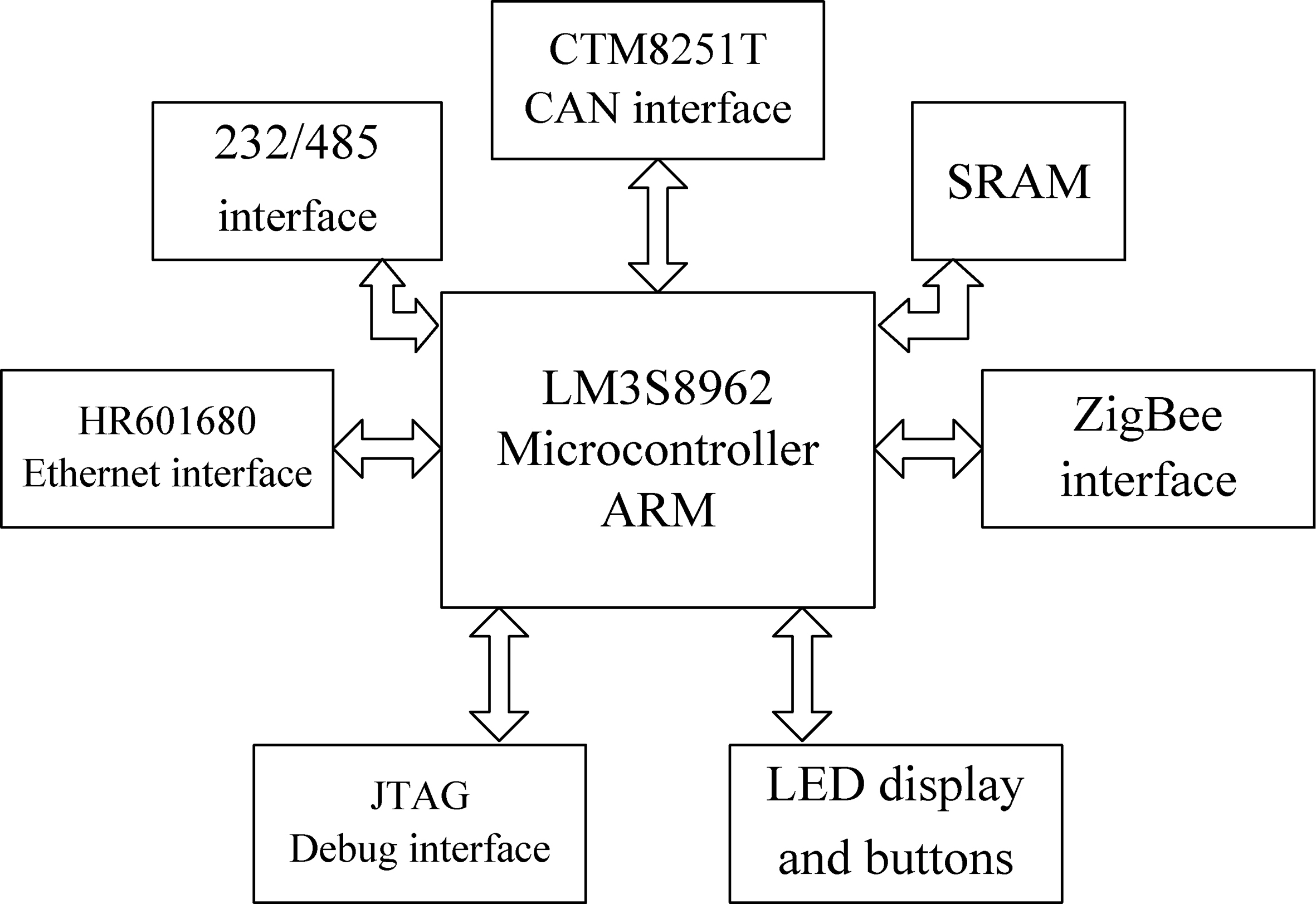
The structure of the test system is shown in Fig. 15. Eight terminal nodes and one coordinator are used to form the mesh network to test the communication distance and the network performance. First, the coordinator initializes the system. Then, the eight terminal nodes are added to the network by route search. When the coordinator receives the application message of the terminal node, it first checks whether the node belongs to this network. If it does not, it discards the node. The coordinator completes the registration of terminal nodes until all terminal nodes are connected successfully.
The structure of test system.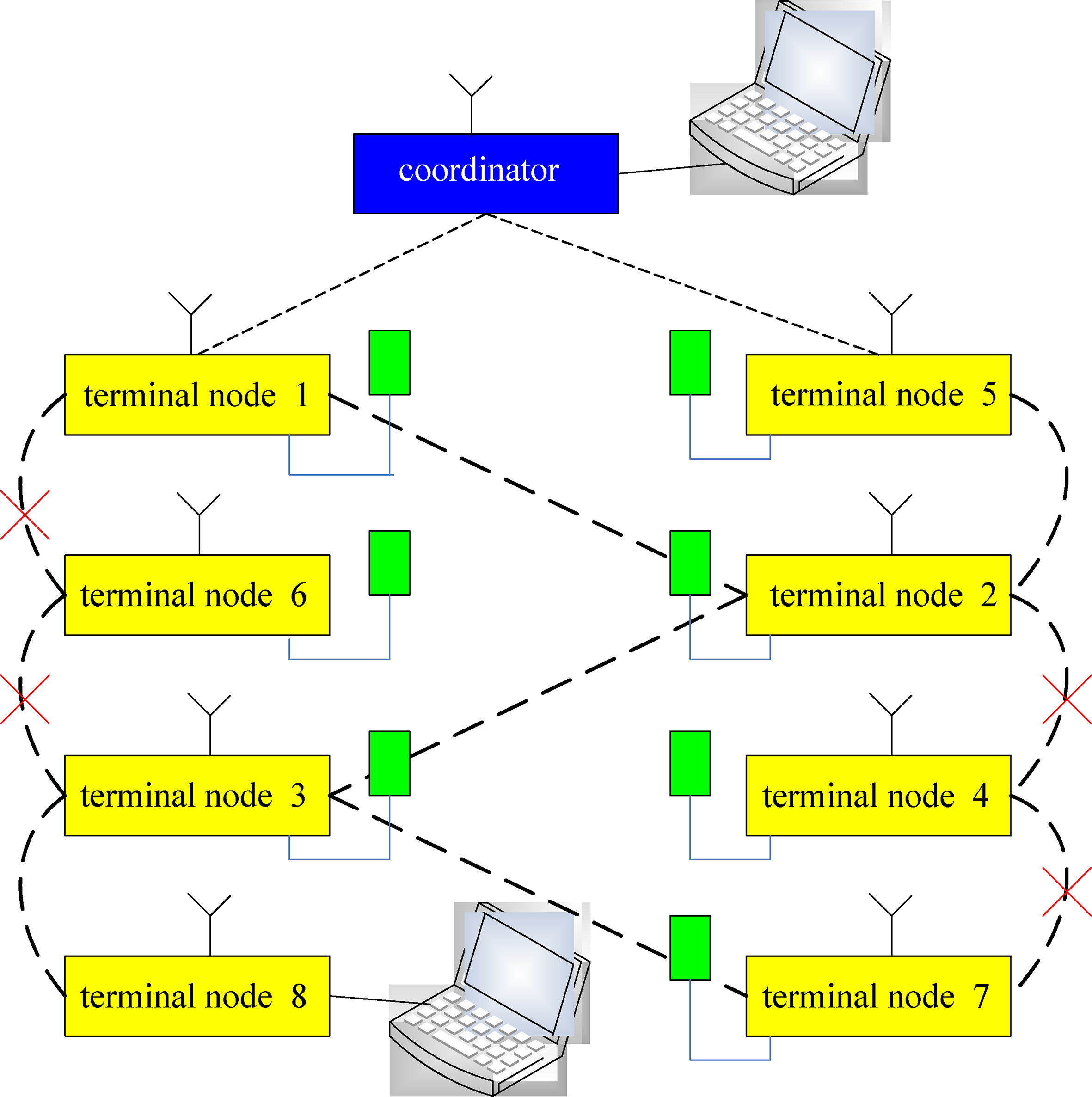
The test showed that the maximum communication distance between nodes in an open area is 900 m. If the distance between nodes is far enough that node 3 can not be directly routed by node 1 and node 7 can not be directly routed by node 2, then, node 6 and node 4 are powered off to cut off the original routing path. The data of node 3 is also routed to node 1 by node 2, and the data of node 7 is routed to node 2 by node 3. This allows the communication function of the system network to return to normal.
The results of this test show that the other nodes can search the routing path again if a node fails to communicate. The network has self-organization and self-healing functions to ensure stability, robustness and anti-interference, which meets the requirement of the wireless navigation lighting system in a temporary emergency airfield.
Navigation light is the “eye” of an airport, which is an important guarantee for the safe taking off and landing of an aircraft. It is indispensable for any airport. In view of a series of problems existing in the airport’s navaid lighting, it proposes a research on LED navaid lighting terminal node based on wireless ad hoc network in this paper. It can be applied to energy saving and consumption reduction, lighting guidance, online inspection and fault location, flexibility and manoeuvrability of combat readiness airport, perception of lighting nodes, etc. It can be combined with power electronics technology, computer technology, wireless communication network technology, automatic control technology and so on, which has a broad application prospect for improving the intelligence of navigation aid lighting system and realizing the information of “intelligent airport”.
Footnotes
Acknowledgments
The authors acknowledge the guiding project of the 2019 Natural Science Foundation of Liaoning Province (Grant: 2019-ZD-0102).