
Abstract
Traditional denoising methods for Micro-electromechanical Systems (MEMS) gyro signal are required to obtain a priori noise statistical properties, which result in poor denoising performance in MEMS gyro utilized in Micro-Inertial Measurement While Drilling (MWD), due to the unknown and complex noise characteristics in MWD. According to this problem, a kind of gyro signal denoising method based on sparse decomposition without a requirement of the priori noise characteristics, utilizing a newly designed atom dictionary, is proposed. Firstly, the MEMS gyro output differential equation is established on the basis of the physical mechanism of the MEMS gyro, then the real MEMS gyro output signal characteristics are analyzed according to the solution of the differential equation. Secondly, the characteristic wave atom most similar to the gyro output signal is designed. Finally, the gyro signal sparse decomposition denoising experiments based on the designed atom dictionary are conducted, compared with the wavelet threshold method and Kalman filter. The experiment results show that the proposed denoising method based on sparse decomposition utilizing the newly designed atom dictionary outperforms wavelet threshold method and Kalman filter in MEMS gyro signal processing of MWD, especially when the noise statistical properties of gyro signal are completely unknown.
Introduction
In recent years, Micro-electromechanical Systems (MEMS), are becoming increasingly popular in the drilling industry, because of their low cost, small footprint, long service life, improving precision, impact resistance, and low power consumption. These advantages make Micro Inertial Measurement Unit (MIMU), based on MEMS triaxial accelerometer and triaxial gyroscope, perfect candidates for Measurement While Drilling (MWD) characterized by high temperatures and substantial vibrations and shocks [1, 2, 3, 4, 5, 6, 7, 8]. As the main surveying device of MIMU, the triaxial gyro is capable of providing continuous triaxial angular velocity measurement used to obtain the orientation [3, 9, 10]. However, the substantial irregular noises associated with the surveyed MEMS gyro signal render the MEMS gyro-based MWD method unsuitable for long-term continuous orientation estimation [11, 12, 13]. Therefore, denoising the surveyed gyro signal and extracting real gyro signal are of great importance to improve the orientation estimation accuracy.
Among existing MEMS gyro signal denoising algorithms, the wavelet denoising method [14, 15, 16], famous for excellent time-frequency resolution characteristics, aims at obtaining the wavelet coefficients over different scales utilizing Mallet algorithm and setting to zero the smaller wavelet coefficients, in comparison with the preset threshold coefficient. However the determination of preset threshold coefficient is required to obtain a priori statistical properties of signal noise [17, 18], which leads to poor performance in MEMS gyro signal denoising utilized in MWD.
Another popular class of MEMS gyro signal denoising method is based on the Kalman filter [11, 19, 20], the basic idea of which is to establish the MEMS gyro signal state and observation model with random interference and noise, and then using the linear minimum variance of the state covariance sequence as the optimization criterion to give the optimal estimate of the MEMS gyro signal. Under certain stochastic input assumptions, the Kalman filter acts as the optimal state estimator for a linear system [21, 22]. However the input assumptions are not always suitable for long-term continuous estimation of the MEMS gyro signal, because of the strong random input noise. Besides, the established MEMS gyro signal state and observation model are always inapplicable in long-term continuous filtering process in MWD [23, 24]. As a result, this Kalman filter-based method is unsuitable for MEMS gyro signal de-noising in MWD.
Traditional MEMS gyro signal denoising methods, as shown above, require to obtain a priori statistical properties of signal noise, which result in poor denoising performance in MWD, due to the unknown and complex noise characteristics of gyro signal in MWD. To resolve the above problems, a kind of MEMS gyro signal denoising method based on sparse decomposition is proposed, when the priori statistical properties of gyro signal noise are unknown while drilling.
From the perspective of sparse decomposition and sparse representation while drilling, the surveyed MEMS gyro signal consists of two components, namely the real gyro signal and noises composed of quantization noise, rate random walk, bias instability, angular random walk, rate ramp and random noise. These noises, characterized by random, uncorrelation and uncertain structures, are uncorrelated with the real gyro signal, while the real gyro signal is a sparse component of the surveyed MEMS gyro signal with a certain inherent feature. Therefore, we can design an over-complete atom dictionary D, atoms of which correlate well with the real gyro signal structures, then the real gyro signal can be faithfully recovered from the measured gyro signal while drilling, completing the MEMS gyro signal denoising process without prior information of the noise statistical characteristics.
Analysis of the characteristics of MEMS gyro signal for MWD
The structure of MWD MEMS gyro is shown in Fig. 1, and the working principle of which is described as follows: The mutual reversed-phase AC voltage is applied to the electrostatic comb driver in pairs, with electrostatic force generated at the same frequency as the AC voltage. Under the action of electrostatic force, electrostatic comb driver starts vibration in the input axis and achieves resonance state by means of a control circuit. According to the dynamics mechanism of the gyro, when the gyro senses angular velocity on sensing-axis (Z-axis), the gyro will apperceive the Coriolis inertial force Output-axis (Y-axis) modulated by vibration signal in Input-axis (X-axis), and the apperceived Coriolis inertial force is proportional to angular velocity in size. Under the action of the Coriolis inertial force, vibration is produced along Output-axis with the detection capacitance changed, and then the electrical signal on the output-axis is obtained by using micro-capacitance circuit to detect changes in capacitance; Finally, the Output-axis signal is demodulated by the vibration signal of the Input-axis, and then becomes the final gyro output signal proportional to the angular velocity via a low-pass filter.
Structure sketch of MWD MEMS gyro.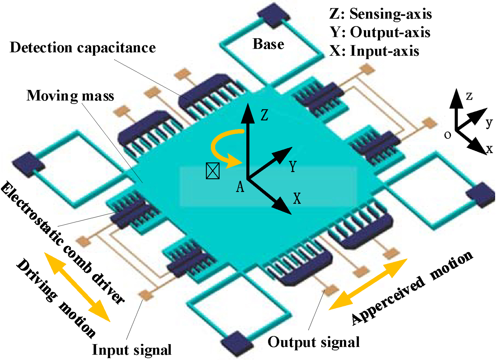
For a clear understanding of the following derivation, we first define a notation that will be utilized throughout this Section. We refer to the dynamic frame A-XYZ attached to the moving mass, and define the inertial frame o-xyz fixed in inertial space, as shown in Fig. 1.
When the dynamic frame A-XYZ rotates in the inertial frame o-xyz at an angular velocity
where,
Both the displacement and velocity of Z axis are much smaller than those of X axis and Y axis,because the stiffness of Z axis is much larger than that of X axis and Y axis in this MWD MEMS gyro, namely:
where
For better understanding the nature of the MWD MEMS gyro, the following derivation is to achieve a reasonable simplification of Eqs (2) and (2). Assuming that: (1) the moving mass is only applied to electrostatic force in X-axis without disturbing force; (2) the input angular velocity is much less than the natural frequency
Equations (4) and (5) describe the general form of single-axis MWD MEMS gyro input and output differential equations.
The particular solution of the output equation is obtained from the Eqs (4) and (5):
where,
The equation is given by the output Eq. (5):
where,
The root of Eq. (5) is computed by the Eq. (7):
The damping can be divided into three cases according to the damping ratio. Case(1): over-damping, when
The general solution of the output equation on condition of underdamping is given by Eqs (4), (5) and (8):
where
According to Eqs (6) and (9), the full solution of the MWD MEMS gyro output signal is:
where,
As can be readily seen from Eq. (10), the real MWD MEMS gyro output signal is composed of two components, and the first part is the particular solution with the driving frequency
In MWD, the surveyed gyro signal is often mixed with quantization noise, rate random walk, bias instability, angular random walk, rate ramp and random noise. From the perspective of signal generation mechanism, each of the components in gyro output signal must be caused by a corresponding drive, on account of which, the conclusion can be reached that: the MEMS gyro signal is sparse.
According to the sparse decomposition theory, the surveyed gyro signal in MWD consists of two parts: real gyro signal and noise. The real gyro signal is the sparse component of the surveyed gyro signal and characterized by the particular structure, as shown in Eq. (10), so that only some basis functions associated with the real gyro signal structure are sufficient to represent the true MEMS gyro signal, and the rest of the surveyed gyro signal can be viewed as the corresponding ‘noise’. Then the surveyed MEMS gyro signal can be expressed as a kind of combination of expansion functions. Suppose that
where
Equation (11) can be rewritten in the following matrix form:
where
The sparse decomposition framework,as shown in Eq. (12) , is attractive as it implies that the real gyro signal can be faithfully recovered from the measured gyro signal in MWD, without prior information of the noise statistical characteristics and using
Principle of atom dictionary design
As shown above, decomposing the noisy MEMS gyro signal over a family of atoms well localized both in time and frequency performs as an effective denoising method. Such atoms are called time-frequency atoms. We suppose that a single window function
MEMS gyro atom dictionary design
The essence of signal sparse decomposition is to obtain the original signal reconstruction accurately utilizing as few atoms as possible from the time-frequency atom dictionary D. If the designed time-frequency atoms can not correlate well with the signal structures, the finished decomposition is not necessarily complete signal sparse representation. Besides, the signal is subdecomposed into several elements and its information is diluted.
Equation (10) suggests that the real MEMS gyro output signal in MWD consists of periodic and exponential decay elements, and other existing components in the measured MEMS gyro output signal should be noises. Thus, exponential decay sine waves atoms can be selected to construct the time-frequency atom dictionary utilized in the sparse decomposition of the noisy MEMS gyro output signal, because of its good correlation with the two particular elements of a real MEMS gyro output signal.
The following function
where
According to Eq. (13), an atom is determined by
The advantage of choosing Eq. (13) as an atom wave is its similarity to the transient response of the gyro output signal, so it is very suitable for extracting the attenuation waveform element in the gyro signal. Figure 2 shows a 512 points discrete atomic time domain waveform according to Eq. (13), where
A constructed atom curve.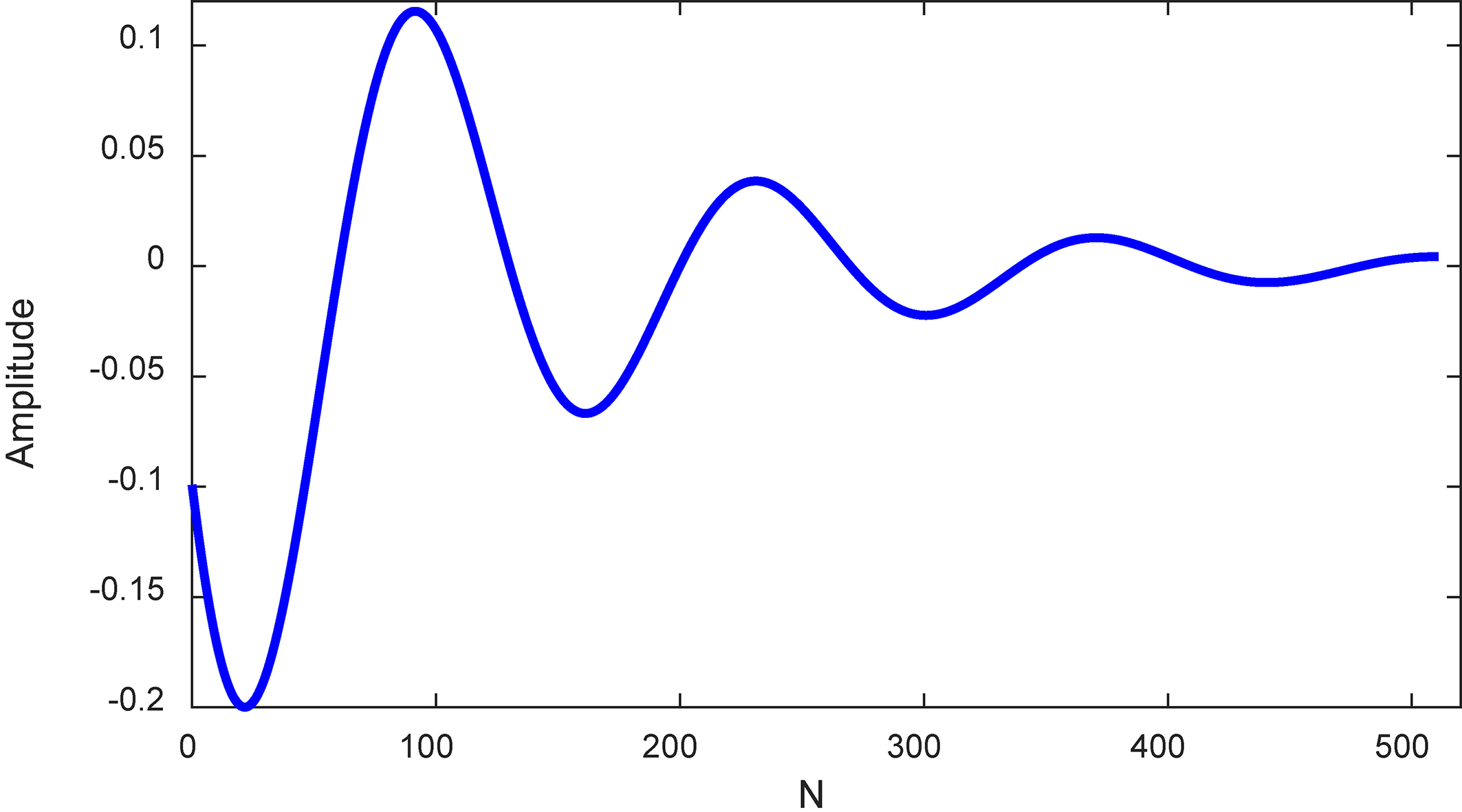
In addition, when the scale factor
Constructed atom curves of different 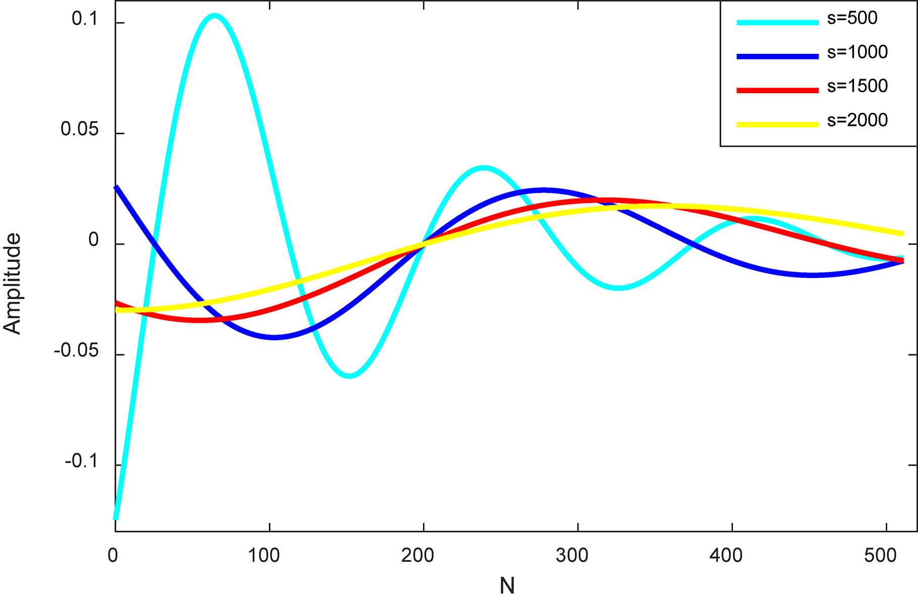
The general issue behind MEMS gyro signal sparse decomposition is to choose the atoms best adaptive to the structures of the signal to be decomposed, among all the time-frequency atoms of a large dictionary. In this Section, we introduce an algorithm called matching pursuit to decompose the surveyed MEMS gyro signal into a linear expansion of atoms belonging to the redundant dictionary D. A matching pursuit is a greedy algorithm that chooses an atom correlating well with the real gyro signal structures at each iteration.
According to Section 2.2, the real MEMS gyro signal behaves as a finite dimensional signal in the base space and is with sparsity, which indicates it can be efficiently represented by an appropriate countable subset of atoms from D.
Therefore, the reconstructed gyro signal can be written as:
where
As the dictionary D is very redundant, the choice of the sparse coefficient
where
Then the iteration process is performed as follows:
The MEMS gyro signal was obtained as follows:
MEMS gyro signal sparse decomposition experiment
From MEMS gyro output signal characteristics in Section 2.1, we can obviously learn that the real MEMS gyro signal is mainly composed of two structural types: periodic sinusoidal component and exponential attenuation component. Turntable swing experiment was designed as shown in Section 5.1 to check whether Eq. (10) can effectively characterize the real MEMS gyro signal and whether the Matching Pursuits (MP) sparse decomposition utilizing the designed atom dictionary based on Eq. (13) can effectively extract the real gyro signal from the noised MEMS gyro signal.
Considering that the angular velocity data collected from the turntable itself has much higher accuracy than that of MEMS gyro on measurement precision, the angular velocity measured by the turntable is approximately taken as the real angular velocity. Meanwhile, the installation error between MEMS gyro and turntable can be neglected. Then MP sparse decomposition based on the newly constructed atom dictionary of Eq. (13) is adopted to denoise the MEMS gyro signal, with the MP iteration times of s 15.
The angular velocity data collected from the turntable and the MEMS gyro are shown in Fig. 4a and b respectively. The denoised MEMS gyro signal utilizing MP sparse decomposition based on the newly designed atom dictionary of Eq. (13) and the residual MEMS gyro signal after sparse extraction are described in Fig. 4c and d respectively.
Gyro signal sparse decomposition and reconstruction.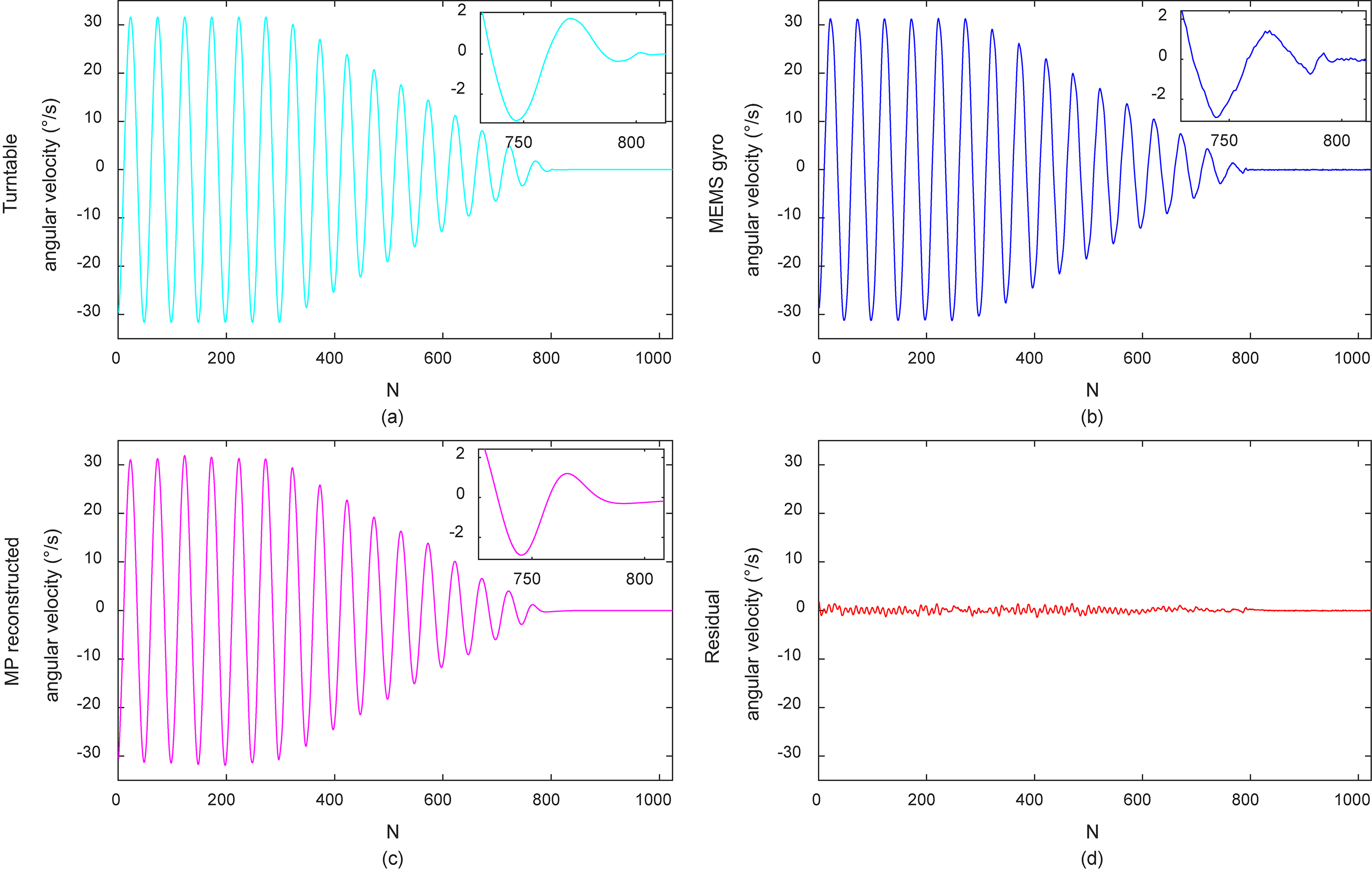
As can be readily seen in Fig. 4b, the obtained MEMS gyro signal, which is featured with periodic sinusoidal and exponential attenuation components, involves substantial noises in comparison with the angular velocity measured by the turntable in Fig. 4a. Comparing Fig. 4a and c, we can find clearly that the MP sparse decomposition based on the newly constructed atom dictionary of Eq. (13) achieves perfect approximation to the real MEMS gyro signal; Comparing Fig. 4a–c, lots of noises in the MEMS gyro output signal are removed, after sparse decomposition and reconstruction of the measured MEMS gyro signal, and the removed noise is shown in Fig. 4d.
In order to comprehensively compare the denoising performance of MP sparse decomposition based on the newly constructed atom dictionary of Eq. (13), a total of 3 sets of MEMS gyro signal denoising methods are implemented, corresponding to the wavelet threshold, Kalman filter and sparse decomposition denoising utilizing the designed atom dictionary respectively. The 3 methods’ adjustable parameters are set to as follows: (1) Wavelet threshold denoising experiment: the Db4 orthogonal wavelet base is selected to perform the 5 scale wavelet decomposition of the MEMS gyro output signal, and the ‘minimax’ soft threshold is used to filter and reconstruct the MEMS gyro signal; (2) Kalman filter experiment: the values of coefficients are set to
The experiments are repeated 5 times, with each time using different length-10000 data from Section 5.1, to reduce accidental errors. A certain trial is shown in Fig. 5. The dynamic Signal-to-Noise Ratio(SNR) and Root Mean Square Error (RMSE) values of wavelet threshold, Kalman filter, and sparse decomposition utilizing the designed atom dictionary are computed respectively. The results are summarised in Table 1, where each value stands for the mean of all 5 experiments.
Comparison of SNR/RMSE
Comparison of SNR/RMSE
Comparison of gyro angular velocity denoised by Db4 wavelet, Kalman filter and Sparse decomposition.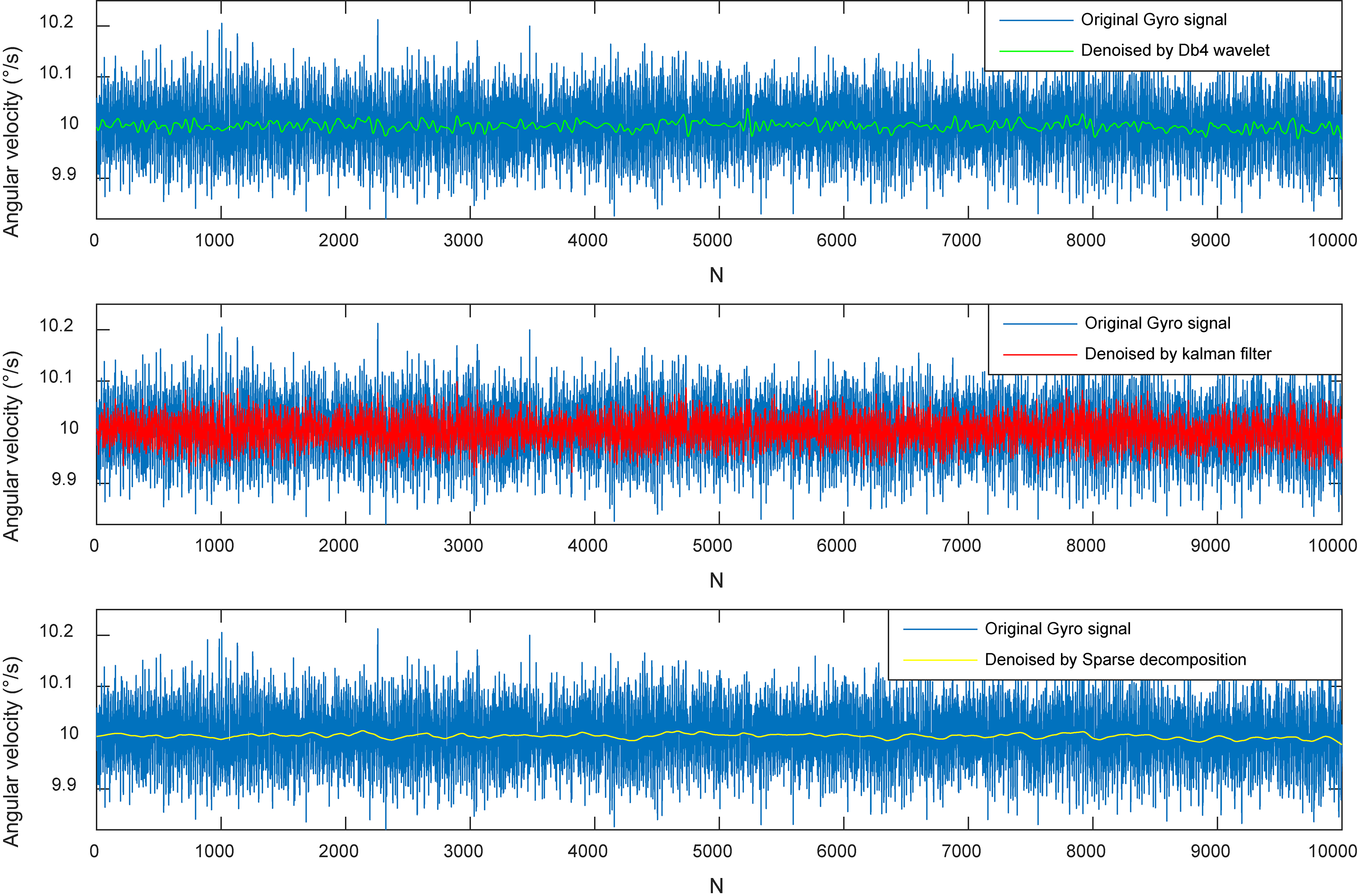
Comparing the results of the Db4 wavelet threshold method, Kalman filter and MP sparse decomposition denoising utilizing the designed atom dictionary, MP sparse decomposition denoising method utilizing the designed atom dictionary is superior to the other two methods in denoising performance quantized by SNR and RMSE.
In this paper, a kind of denoising method based on sparse decomposition in MEMS gyro utilized in MWD is proposed. This denoising method is most featured of not requiring information of noise statistical properties of gyro signals as a prior. However, the real gyro signal can be faithfully recovered from the noisy gyro signal while drilling depending on that the utilized atom dictionary should correlate well with the real gyro signal structures. Therefore, the emphasis of this study lies in: (1) Analysing the structures of the real gyro signal based on theoretical derivation and experimental verification; (2) Designing atom dictionary based on the characteristic of the real gyro signal; (3) Checking the performance of the newly designed atom dictionary utilized in the gyro signal sparse decomposition denoising compared with the wavelet threshold method and Kalman filter. The experiment results show that the proposed sparse decomposition denoising method utilizing the newly designed atom dictionary outperforms wavelet threshold method and Kalman filter in MEMS gyro signal processing of MWD, especially when the noise statistical properties of gyro signal are completely unknown. The results suggest the newly designed atom dictionary is applicable, providing a reference for the further application of sparse decomposition in denoising MEMS gyro signal while drilling.
Footnotes
Acknowledgments
This work is financially supported by the project of National Natural Science Foundation (60834005) and the key project of natural science research in Anhui Universities (KJ2018A0873) and the key project of the supporting plan for excellent young talents in Anhui Universities (gxyqZD2019105).