
Abstract
In industrial applications, EtherCAT control technology requires the use of TwinCAT control software with dedicated servos for real-time control. In order to solve the limitations of the practical application of EtherCAT, this experiment combines EtherCAT real-time control technology with Simulink Real-Time real-time control technology to design a new EtherCAT real-time control technology based on Simulink Real-Time. In the experiment, D2 delta robot is used as the control object, and the real-time control environment of Simulink Real-Time is set up to build the EtherCAT real-time communication model. The established real-time control model is added to the robot control system to realize the motion control of the robot.
Introduction
In the field of industrial automation, with the improvement and standardization of Ethernet, Ethernet-based motion control systems have attracted more and more attention, especially the control technology based on EtherCAT (Ethernet for Control Automation Technology). EtherCAT has many advantages over traditional Ethernet: First, EtherCAT has a very high propagation speed, and it only takes 30 us to read one thousand distributed digital input/output program data. Second, The synchronous clock mechanism of EtherCAT enables highly synchronized control of multiple axes.
Simulink Real-Time technology in Matlab allows real-time applications to be created in the Simulink model and downloaded to a dedicated target computer connected to the control system. Simulink Real-Time technology can use the driver block to extend the Simulink model to automatically generate real-time applications. Simulink Real-Time can also execute interactive or automatic run control programs on dedicated target computers with real-time kernel, multi-core CPU, and I/O communication protocol ports.
In this research, the advantages of EtherCAT’s real-time control technology and the creation of Simulink Real-Time real-time control program are combined to form a real-time EtherCAT control technology based on Simulink Real-Time. This kind of control technology is combined with robot motion control to form a new robot motion control technology.
EtherCAT real-time communication model structure
The EtherCAT real-time communication model is mainly composed of the master station and the slave station, the data frame and the EtherCAT servo controller [6], as shown in Fig. 1. The master station initializes the entire control system and then packs the data to be sent to the slave into a data frame that is passed over Ethernet to the slave. When a data frame enters each slave node, the slave extracts its own data through the PDO addressing method, and then inserts the data to be output into the data frame. When the last slave node receives the data frame data and inserts the output data into the data frame, the data frame will return to the master station.
EtherCAT communication model. 1. Data frame; 2. EtherCAT master station; 3. EtherCAT slave station; 4. EtherCAT servo controller.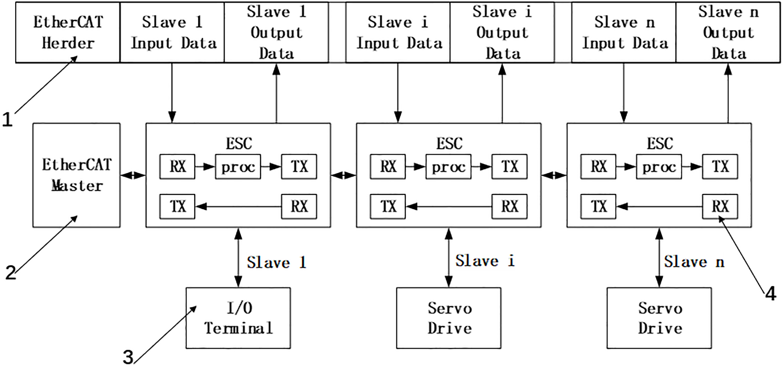
The EtherCAT real-time control system based on Simulink Real-Time is mainly composed of two parts: The first part is to set up the Simulink Real-Time running environment, establish a network connection between the development computer and the target computer, and set the application real-time running environment. The second part is to establish the EtherCAT communication model. In the experiment, a development computer was used for application development, an industrial computer was used as the main station of the EtherCAT communication system, and a servo driver was used as the slave of the EtherCAT communication system.
Simulink real-time operating environment settings
In the experiment, create a TargetPC object in Matlab’s Simulink Real-Time Explorer environment and set its various properties. Setting properties includes three aspects: the communication protocol between the development computer and the target computer, the communication parameters of the target computer, and the boot method settings of the target computer. In the boot configuration of the target computer, a boot program is configured through a removable disk, and the set network parameters and the boot program are stored in a removable disk. When the target computer is booted using the removable disk, the computer enters the real-time control mode.
After the startup program of the target computer is established, the real-time control environment is set in the simulink environment of the development computer. First, add a Simulink Real-Time Scope module to the data output of the model and set the appropriate parameters. Then in Simulink’s “Configurator Parameter” environment, the solver selects “Fixed-step”, sets a fixed step size, and selects “ode4 (Runge-Kutta)” in the solver solver list. Finally, in the code generation options, set the system target file format (srrt.tlc format).
EtherCAT real-time communication module.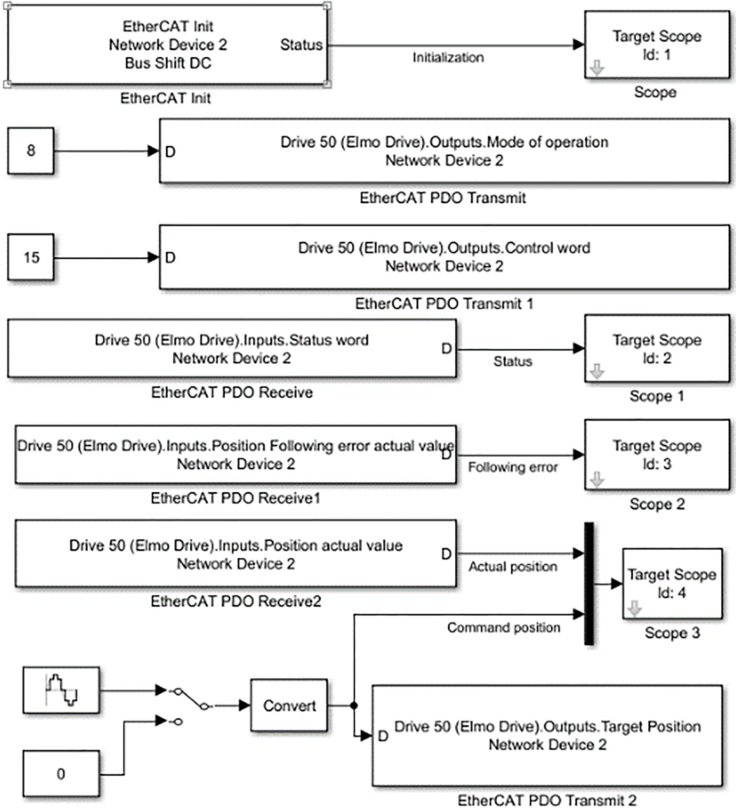
After completing various parameter settings, we can establish a real-time connection between the development computer and the target computer. First, connect the development computer to the target computer through a network cable, and set the network IP address of the target computer so that the development computer can access it. Then use the established removable disk boot program to open the target computer into the Real-Time Control environment. The Simulink model is built in the development computer, and the code generator is started. The system converts the established Simulink control model into a C language program, and then downloads the programs to the target computer through the network to complete the network connection between the development computer and the target computer.
Detailed modeling process of the EtherCAT communication system: First, the TwinCAT2.0 software developed by BECKHOFF is pre-installed in the development computer, and then the XML file related to the drive is copied to the sub-folder related to EtherCAT communication under the TwinCAT software installation package. Set the network IP address of each drive, connect the drive to the development computer through the network cable, and read the drive information through TwinCAT, including the communication information, IP address, and control port of each drive. Set parameters such as PDO communication object, data sampling time and motion control mode of each drive in the I/O communication interface environment of TwinCAT. Save the set parameters as an ENI document for subsequent operations of EtherCAT control.
The EtherCAT communication module in the Simulink Real-Time toolbox is used to build the communication model required for the experiment. Figure 2 shows the EtherCAT real-time communication model built in the experiment.
Experiment
Establishment of robot motion trajectory generator based on Simulink State Flow
The logic control and motion trajectory generation in the experiment will be done in the MATLAB Simulink environment. Through the Simulink Stateflow toolbox, using Stateflow state module and logic control module, combined with the mathematical model of motion trajectory and logic control algorithm, to establish a uniform acceleration and deceleration trajectory generator, as shown in Fig. 3.
Motion trajectory generator based on Simulink State Flow.
The most important part of the trajectory generator is the chart module. Through the state module and condition judging module, combined with the logic control algorithm, formed the core of the motion trajectory. As shown in Fig. 4, the A module is the starting module, the initial motion parameters of the trajectory are set, and the parameters are sent to the Simulink Function function, produces the first trajectory to reach the set starting position. The system will detect whether the target command has changed. When entering a new target command, the system enters the B module, sets the new motion parameters, and then the new motion parameters through the function name to call the trajectory function, generate a new trajectory. During the motion, the B-state module will always detect whether there is a new instruction input. If there is a new instruction input, the system will return to the B module to update the motion parameters, the new motion parameters are sent to the trajectory function to update the trajectory.
Motion Trajectory control based on Simulink Stateflow.
In the trajectory generator, set the starting coordinate to 0 mm, the end point coordinate is 70 mm, the trajectory planning movement time is 4 s. we obtained the position profile, velocity profile, acceleration profile and Jerk profile, as shown in Fig. 5.
Third-order uniform acceleration and deceleration trajectory.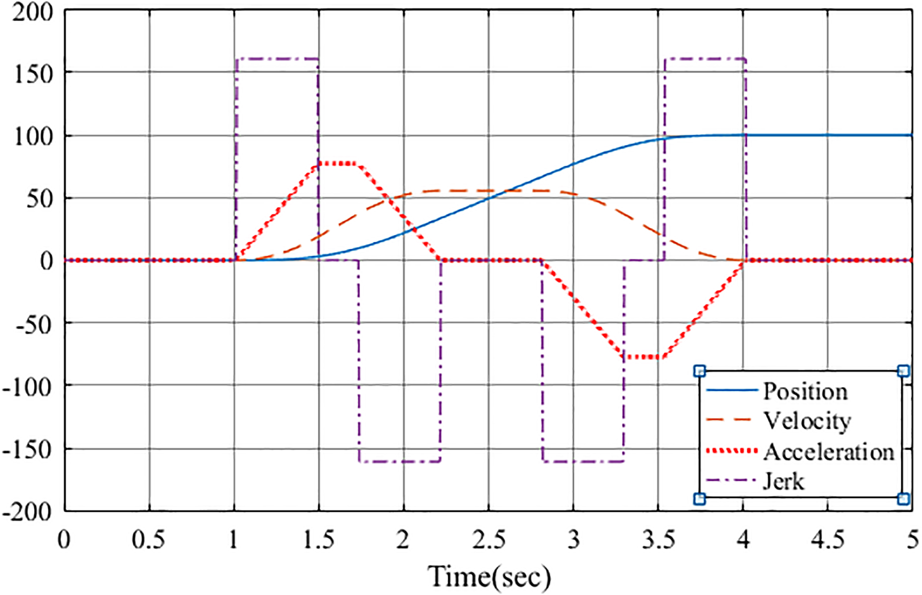
In order to test the practicality of the Simulink Real-Time-based EtherCAT control technology designed in the experiment, the D2 delta robot was used as the control object. In order to achieve precise control of the robot, the kinematics analysis of the robot is first carried out, and the robot’s motion trajectory generator is designed. These control units are integrated into the real-time control system of the experiment, and finally the robot control system built in the Simulink environment of the development computer is shown in Fig. 6.
D2 delta robot motion control system. 1. EtherCAT controller; 2. Trajectory generator; 3. Robot inverse kinematics model; 4. EtherCAT communication interface; 5. Robot forward kinematics model.
D2 delta robot motion control hardware system.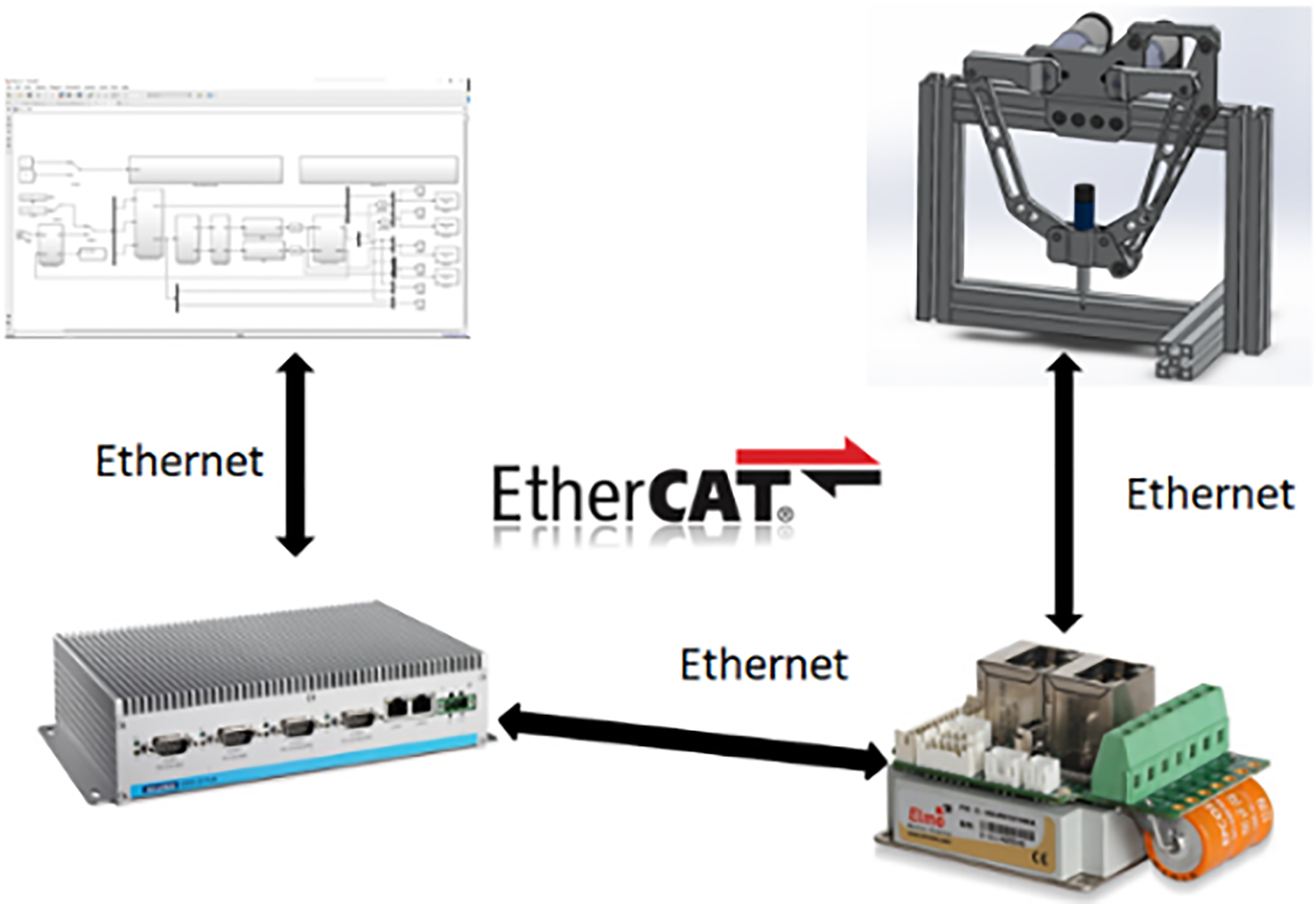
D2 delta robot control experiment platform.
The trajectory generator generates a motion trajectory of the robot end effector, and the inverse kinematics model converts the motion trajectory into a robot’s rotation angle. The control information is transmitted to the servo motor through the EtherCAT real-time control system established in the experiment, and the robot is driven by the servo motor.
Y-axis displacement track actual value and command value comparison.
Y-axis velocity track actual value and command value comparison.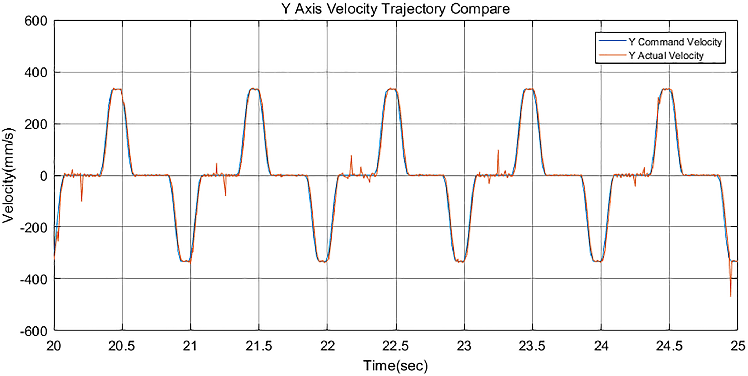
In the construction of the robot hardware control platform, the main development computer is responsible for the construction of the control model and the preparation of the control program. An industrial computer is used as the controller, which is responsible for trajectory calculation and robot kinematics calculation. At the same time, the industrial computer acts as the master station of EtherCAT real-time communication to send control information to the slave station, and accepts the status information fed back from the slave station. In the control system, in addition to driving the motor, the driver acts as a slave of EtherCAT real-time communication, accepts the communication information sent by the master station, and transmits the running status of the motor back to the master station.
The development computer, controller, and driver are connected by a network cable to form a hardware system for real-time motion control of the robot. Figure 7 shows the connection schematic of the hardware control system, and Fig. 8 shows the actual experimental control platform in the experiment.
Experimental analysis
In order to test the control performance of the designed control system, a robot’s motion trajectory is designed within the robot’s range of motion. In the experiment, the actual motion trajectory of the robot is compared with the predetermined motion trajectory, the displacement trajectory, velocity trajectory and acceleration trajectory of the robot are obtained as shown in the figure. Through the analysis of the experimental data in the figure, the actual motion parameters of the robot are exactly the same as the designed parameters, and the feasibility of the EtherCAT real-time control system based on Simulink Real-Time is verified.
Y-axis acceleration track actual value and command value comparison.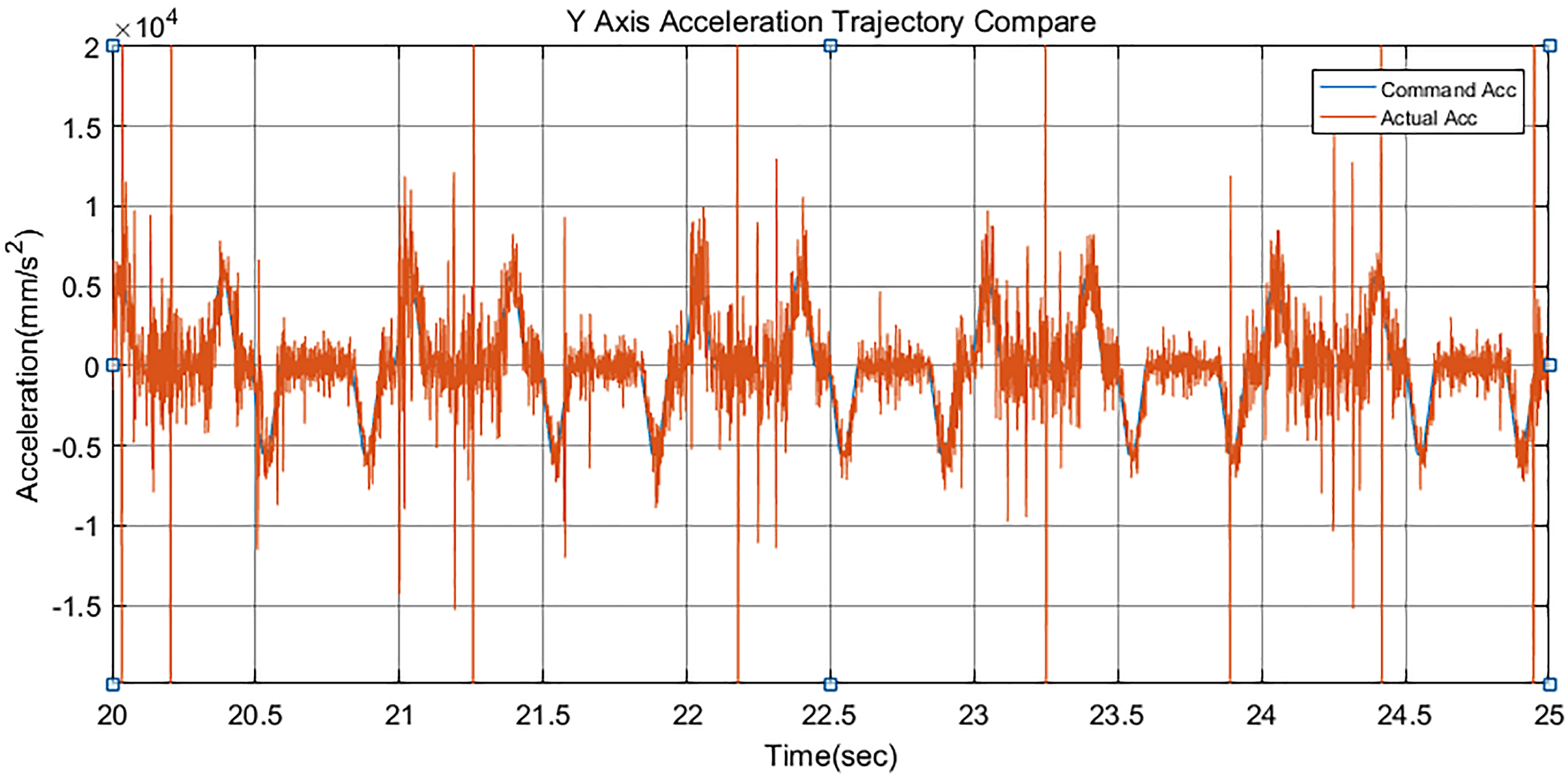
In the experiment, EtherCAT control technology is integrated with Simulink Real-Time real-time control technology, and a real-time EtherCAT control technology based on Simulink Real-Time is designed in MATLAB Simulink environment. The control technology designed in the experiment was applied to the robot motion control, and the practicability of this control technology was verified by experiments.
The new EtherCAT real-time control technology is to build a control model in MATLAB’s Simulink environment, using Simulink Real-Time real-time control technology combined with EtherCAT communication technology to achieve robot control. The advantages of this control method are:
In the robot control, it is not necessary to write complicated program code. In Simulink, each control module is built, and then the control module is converted into a C language control program, and these programs are downloaded to the controller to realize the motion control of the robot. Compared with the traditional EtherCAT control technology, the EtherCAT real-time control technology based on Simulink Real-Time designed in this experiment does not require a dedicated servo device, and the motion control of the robot can be realized by using a general servo driver. This technology improves the practicality and convenience of EtherCAT real-time control technology. In this paper, a new robot control system based on Simulink Real Time is designed, which breaks the traditional control method of robot control by teaching pendant programming, which is of great significance to the innovation and development of robots.
Footnotes
Acknowledgments
This work was supported by Guizhou University.