
Abstract
Because of the low height of the prestressed short rib T-beam bridge and the poor torsion resistance of the main beam, the positive moment in the middle span of the bridge deck will increase correspondingly compared with the normal rib beam bridge. At present, there is little research on the calculation method of the bridge deck of the prestressed short rib T-beam bridge. In this paper, the space finite element method and the continuous one-way slab method are used to calculate the forces on the bridge deck, based on the space finite element method, a finite element elastic supported continuous beam method is proposed to calculate the forces on the bridge deck. By comparing the calculation results of the three methods with the test results, the reasonable calculation method of the bridge deck is studied. The results show that the spatial finite element analysis method can simulate the mechanical performance of the deck of the bridge of the prestressed short rib T-beam bridge well, the stress calculation results are consistent with the test results, and the calculation accuracy is high, which can be used in the actual engineering design; The finite element analysis method of elastic support continuous beam can also simulate the mechanical performance of the deck of the bridge of the prestressed short rib T-beam bridge. The concept of the method is clear, the calculation is convenient, and it is more suitable for the application of engineering design; The calculation results of the continuous one-way slab method are too large to be safe for design.
Keywords
Introduction
With the rapid development of high-grade highways, it has become an inevitable trend to require bridges with lightweight structure and beautiful appearance [1]. Therefore, in order to reduce the average filling height of roadbed, reduce the number of earthwork, reduce land occupation and save project cost, etc. [2, 3, 4], The prestressed concrete short rib T-beam bridge is put forward. The prestressed concrete short rib T-beam has the advantages of convenient construction, reasonable stress, good durability and beautiful appearance [5, 6, 7], however, due to the small height of the structure, the torsional stiffness of the main girder is poor [8, 9], The poisitive mid-span moment of the bridge deck is correspondingly increase [10, 11, 12, 13]. At present, many theoretical discussions have been made on the calculation of bridge deck of different types of bridges [14, 15, 16, 17, 18, 19, 20], however, there is still a lack of theoretical support for the calculation of the bridge deck of this short rib T-beam bridge structure [21, 22]. In this paper, the spatial finite element analysis method, the finite element elastic support continuous beam method and the continuous one-way slab method are used to analyze the mechanical performance of the bridge deck of the prestressed concrete short rib T-beam bridge, and the calculation results are compared with the experimental results to explore the reasonable algorithm of the bridge deck of the prestressed concrete short rib T-beam bridge [23, 24, 25].
Experimental research
Taking Keshan 4
Properties of materials
Properties of materials
Main beam dimensions.
This test is divided into two working conditions for loading. Working condition 1: load the positive bending moment at the middle position of the side span of the bridge deck. When loading, the rear axle of the vehicle is 4 m away from the middle position of the bridge span, the front of the vehicle is facing the pier direction, and the rear of the vehicle is facing the middle position of the bridge span, so that the wheel center at one side of the rear axle of the vehicle is pressed at the middle position of the side span of the bridge deck. Working condition 2: load the positive bending moment at the middle position of the secondary side span of the bridge deck. When loading, the rear axle of the vehicle is 4 m away from the middle position of the bridge span, the front of the vehicle is facing the pier direction, and the rear of the vehicle is facing the middle position of the bridge span, so that the wheel center at one side of the rear axle of the vehicle is pressed at the middle position of the secondary side span of the bridge deck. As the effective working width a
Longitudinal loading position of test (m).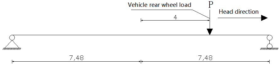
Transverse loading position of vehicle under condition 1 (mm).
Transverse loading position of vehicle under condition 2 (mm).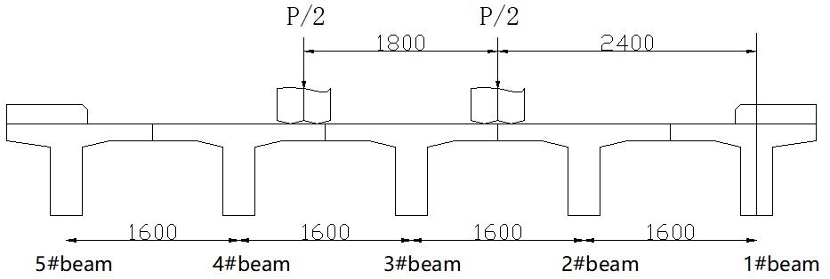
Layout of measuring points (mm).
Under the action of vehicle load, when testing the stress in the middle of the bridge deck span, a strain gauge shall be arranged at the bottom of the slab in the middle of the side span and the secondary side span of the bridge deck. When testing the stress at the fulcrum of the bridge deck, a strain gauge shall be arranged at the top of the slab at the No. 2 and No. 3 fulcrums of the carriageway slab, as shown in Fig. 5.
Analytical method
Space finite element analysis
Model building
Considering that the bridge deck is a slab structure, it is more reasonable and accurate to use the plate element in the modeling. According to the actual structure, the beam element is used for the beam rib and diaphragm beam, and the slab element is used for the bridge deck, the beam rib and the bridge deck are rigidly connected, set the diaphragm according to the actual size at the fulcrum and midspan position, and the diaphragm is orthogonal to the main beam, the boundary condition is general support, and the whole bridge is divided into 252 elements, the space finite element diagram and model diagram are shown in Figs 6 and 7. The calculated load is input in the form of surface load. The side length of rectangular surface load is b1
Schematic diagram of plate-beam composite unit.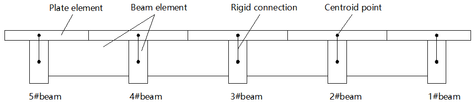
Profile of plate-beam composite unit model.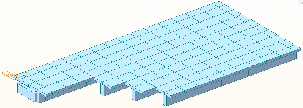
In order to ensure the correctness and accuracy of the established model, the theoretical analysis results of side beams under self weight are calculated according to the design size of structural members and the gravity density of materials, and the results are compared with the finite element analysis results, as shown in Tables 2 and 3.
Comparison of internal forces under dead load
Comparison of internal forces under dead load
Deflection comparison under dead load
Calculation load position diagram of condition 1 m.
Calculation load position diagram of condition 2 m.
It can be seen from Tables 2 and 3 that the finite element analysis results of the composite element of the mining plate beam are in good agreement with the calculation results of the theoretical formula, which verifies the correctness of the finite element model and can be used for the mechanical performance analysis of the completed bridge.
The bridge deck is an elastic support slab supported on the diaphragms and main girder ribs. In order to facilitate the engineering design, a finite element method of elastic support continuous beam is innovatively proposed, which is used for the stress calculation of the bridge deck. The key of this method is the correct calculation of the vertical and torsional stiffness of the elastic support. Due to the huge workload of theoretical methods, it is difficult to apply them to the actual production. Therefore, the following describes the method of calculating spring stiffness by using the finite element model and the method of establishing the finite element elastic support continuous beam model.
Calculation of vertical stiffness of spring by finite element method
In this paper, the calculation location of the carriageway slab is 4 m away from the mid span. Using the spatial finite element model established in Chapter 2.1, add the vertical force of
Calculation of vertical stiffness of the spring.
A sketch of spring torsional stiffness calculation.
Using the spatial finite element model established in Chapter 2.1, a torque of 100 kN
Using arch support can more accurately simulate the elastic support effect of the main beam on the bridge deck. The thrust stiffness of the arch support is used to simulate the vertical spring stiffness of the main beam, and the bending stiffness is used to simulate the torsional spring stiffness. Take the calculation formula shown in Fig. 12a, Then there is a reaction
Calculation diagram of continuous beam method with elastic support.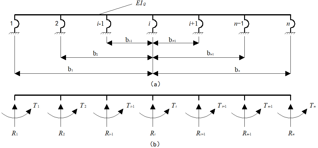
Beam element calculation drawing.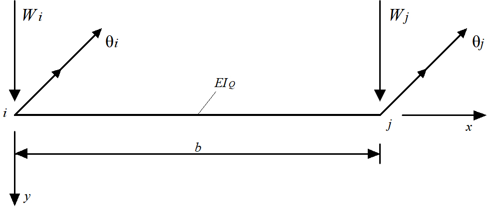
Figure 13 shows the beam unit I. for beam unit I, if the coordinate system shown in Fig. 13 is used, the virtual work principle is used, and the internal displacement is eliminated by condensation method, then the
Among
In the above formulas,
In the formula,
Therefore, when
Thus, the vertical stiffness and torsional stiffness of the spring can be calculated.
In order to ensure the correctness and accuracy of the spring stiffness calculated by the finite element method, the finite element calculation results are compared with the theoretical calculation results, as shown in Tables 4 and 5.
Vertical stiffness of spring
Vertical stiffness of spring
Torsional stiffness of spring
From Tables 4 and 5, it can be seen that the analysis results of the finite element method are in good agreement with the theoretical calculation results, which verifies the correctness of the calculation of spring stiffness by the finite element method, and can be used to calculate the spring stiffness of the elastic supported continuous beam.
The beam element is used to establish the finite element model of the continuous beam with elastic support. The boundary condition is the form of point spring, and the spring stiffness is calculated according to the results in Sections 2.2.1 and 2.2.2. The calculated load is applied to the model in the form of uniform load of beam element, and the distribution length of uniform load is
Schematic diagram of elastically supported continuous beam.
Calculation load application position diagram of condition 1 and 2.
The length width ratio of the bridge deck is La/Lb
Pivot negative moment:
Medium-span bending moment:
among them
In order to verify the correctness of the analysis method of the bridge deck of the prestressed short rib T-beam bridge, the theoretical calculation results are compared with the experimental results under the same technical standards and loading conditions.
See Tables 6 and 7 for the theoretical calculation and test results of stress at each measuring point under the load of condition 1 and 2.
Stress comparison of working condition 1
Stress comparison of working condition 1
Note: the negative number in the table represents the tensile stress.
It can be seen from Table 6 that the average value of BY1 measurement result is
Stress comparison of working condition 2
It can be seen from Table 7 that the average value of BY3 measurement result is
Comparative analysis of stress value of each measuring point.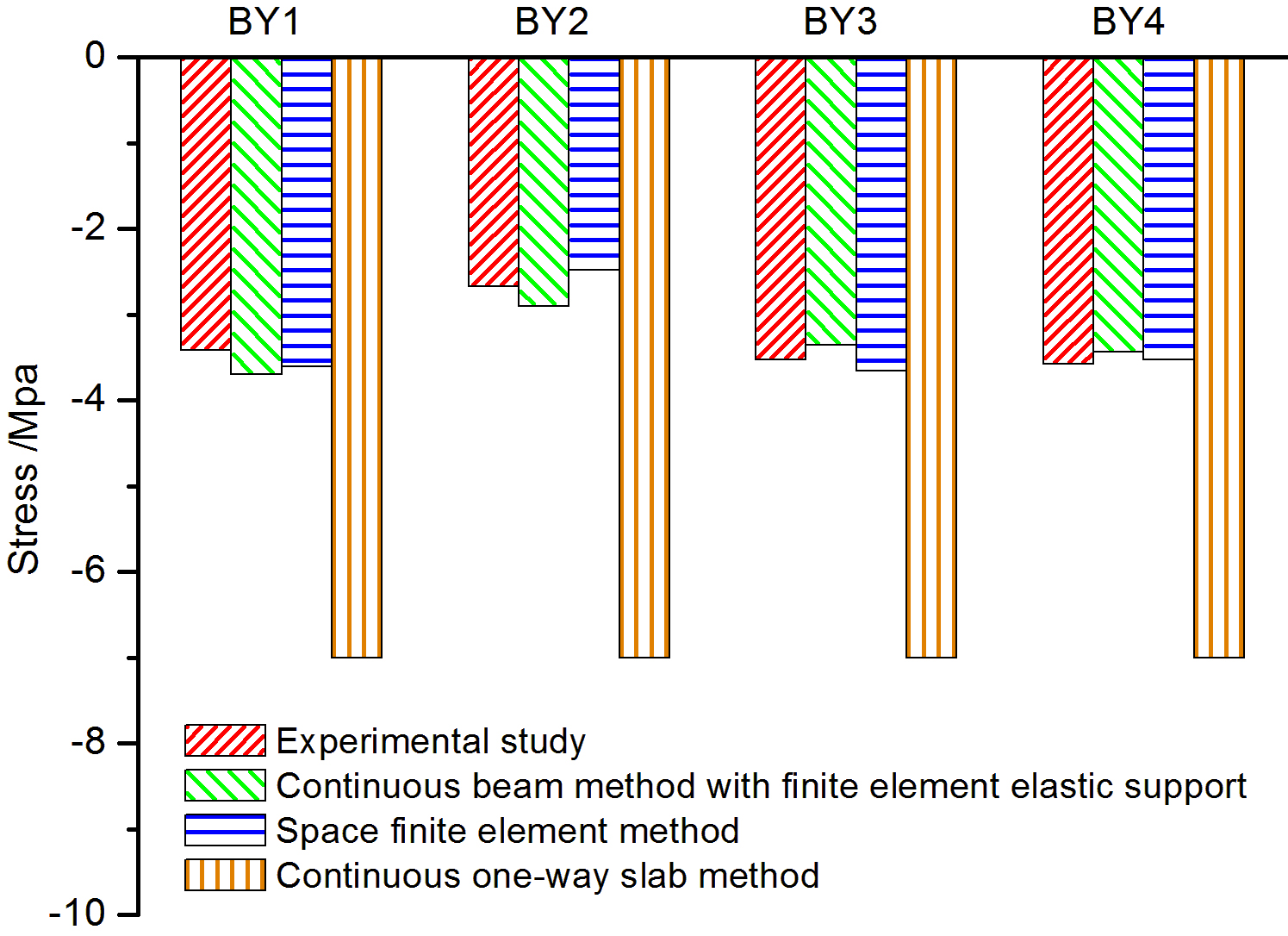
It can be seen from Tables 6 and 7 and Fig. 16 that there is no significant difference between the results calculated by the finite element analysis method and the spatial finite element analysis method. The error mean of the calculation results of all measuring points by the spatial finite element analysis method is 4.42, and the error mean of the calculation results of all measuring points by the finite element analysis method is 6.38, it shows that the spatial finite element analysis method is more close to the test results, and the calculation results are more consistent with the actual. Theoretically, the spring stiffness of the elastic supported continuous beam is calculated by using the spatial finite element model, and the calculation results of the two should be completely unified. However, there are inevitably some systematic errors in the simulation process. It is precisely because of these errors that the calculation accuracy of the elastic supported continuous beam method is slightly lower than that of the spatial finite element analysis method. Comparing the calculation results of the finite element method with the test results, we can see that the spring stiffness is reasonable, and the method used to calculate the spring stiffness in this paper is feasible. The calculation results of continuous one-way slab method are much larger than the test results. The reason for this phenomenon is that the analysis method is partial to safety consideration, and a large safety factor is set in the calculation.
Theoretical research and innovation are made on the calculation method of the bridge deck of the prestressed short rib T-beam bridge, and the rationality of the method is verified by the completion test. The bridge deck is simplified as a continuous beam with elastic support on the main beam rib, and the finite element method of elastic support continuous beam is innovatively proposed for the stress calculation of the bridge deck.
Through the comparative analysis of theoretical calculation results and test results, the following conclusions are drawn:
The new finite element analysis method of elastic support continuous beam can accurately calculate the mechanical properties of the deck of the bridge of the prestressed short rib T-beam bridge. The concept of the method is clear, the calculation is convenient, and it is more suitable for the application of engineering design. The method of using space finite element model to calculate the spring stiffness of continuous beam with elastic support is put forward. The result is accurate and practical.