
Abstract
Virtual reality technology has been applied in virtual labs and remote experiment teaching. This paper designs an electronic circuit virtual laboratory based on virtual reality technology, and relevant experimental teaching content. The system uses Unity 3D and 3ds max tools to build a three-dimensional model of general instrumentation, electronic components, and laboratory scenes in electronic circuit experiments. The C# is used to develop general virtual instrumentation functions and electronic circuit simulation, the electronic circuit virtual reality laboratory based on VR equipment was realized.
We have developed VR electronic circuit virtual laboratory on PC and web. Students can use VR electronic circuit virtual laboratory to learn basic electronic circuit knowledge and carry out electronic circuit virtual experiment immersively.
Introduction
Due to the limitation of time, equipment, and space for electronic circuit experiments in universities, the experimental process is limited to just a few hours in the laboratory. This is undoubtedly a shackle to the improvement of students’ hands-on ability and practical ability. Virtual laboratory based on network technology can not only let students get rid of the time and space restrictions, but also avoid the risks brought by real operation. Because the “equipment” and “components” of the virtual laboratory are virtual, the equipment can be updated at any time according to the situation, saving the cost of purchasing equipment.
Under the current situation that virtual reality and augmented reality technology have been widely developed, the VR electronic circuit laboratory is a supplement to the traditional electronic circuit laboratory. It is a hot issue that how to use the VR technology to construct a virtual laboratory of electronic circuits where students can do experiments [1, 2, 3]. This article designs a virtual laboratory of electronic circuits based on virtual reality technology. As for modeling, we uses Unity 3D and 3ds max as a platform for 3D modeling and system development. As for the logic of virtual laboratory, we use C# language to develop general virtual instrumentation functions and electronic circuit simulation. The electronic circuit virtual laboratory is easy to use, rich in content, and highly scalable. Students can use the system to remotely learn basic electronic circuit knowledge through the network and conduct electronic circuit virtual experiments. Therefore we developed the Virtual Electronic Circuit Laboratory in PC and Web. And we have applied the Web version into actual teaching.
Research status of VR at home and abroad
The United States is the birthplace of VR technology. At present, the basic research in this field in the United States mainly focuses on four aspects: perception, user interface, background software and hardware. Especially in aerospace applications, NASA has now established aeronautical and satellite maintenance VR training systems, space station VR training systems, and has established a VR education system that can be used nationwide. The Computer Department of the University of North Carolina (UNC) is the earliest university to conduct VR research. They mainly study molecular modeling, aviation driving, surgical simulation, architectural simulation, etc. Dr. David Warner and his team at Loma lAnda University Medical Center have successfully used computer graphics and VR devices to explore problems related to neurological diseases and pioneered a VR pediatric therapy. The Massachusetts Institute of Technology (MIT) is a pioneer in artificial intelligence, robotics, and computer graphics and animation, which are the foundations of VR. In 1985, M1T established a media lab to conduct formal research into virtual environments. The Human-computer Interface Technology Lab at the University of Washington’s Washington Technology Center brings VR research to education, design, entertainment, and manufacturing [4].
With the development of computer graphics, computer systems engineering and other technologies, virtual reality has been highly valued by the relevant departments and scientists in China. The VR technology has cause the concern of people from all walks of life in China. The ninth Five-year Plan, the National Natural Science Foundation of China, and the National High Technology Research and Development Plan have regarded research on virtual reality technology as key research projects. Many domestic research institutions and universities are also conducting research and application of virtual reality technology and have achieved some good research results [5]. At present, virtual reality technology is widely used in dozens of important industries such as urban planning, education and training, cultural relics protection, medical treatment, real estate, Internet, exploration and mapping, manufacturing and aerospace. In educational applications, Professor Huang Xiuli of Shaanxi Normal University led a team to develop a virtual reality game design framework for English learning based on the APT model for fourth-grade students to learn English in a primary school in Xi’an and achieved good results [6]. In terms of architectural applications, the “Potala Palace” made by the National Disc Engineering Research Center of Tsinghua University uses QuickTime technology to realize a large panoramic VR system.
Introduction of main development tools
Unity 3D
Unity is a powerful game engine that can be used to develop games for PC, smartphones and tablet PC, and game player. Using Unity engine, you can develop games quickly. Developers only need to create an object, and then create a script to control how it exists to run the game. And there are rich plugins in the resource store for developers to use, greatly reducing the time for developers to repeat work. In the development of VR applications, Unity 3D has an extremely outstanding advantage, borrowing its unique 3D development environment combined with HTC VIVE can develop satisfactory VR games [7].
Unity 3D has its own 3D graphics editor, which is usually powerful enough to make a full game model. However, in the game development industry, programmers and model creators are often different people in different environments, and Unity 3D still lags in visual effects compared to other specialized modeling software. Therefore, we use 3ds max for modeling.
3ds max
3ds max has many features such as advanced rendering and simulation functions, a powerful drawing, texture and modeling toolset, and a smoother multi-application workflow. 3ds max has a very good price-performance ratio, and the requirements for the hardware system are relatively low. The production process of 3ds max is very simple and efficient, which can make beginners get started quickly. The model can be quickly created through instructions. In its subsequent high version, the operability is also very simple, which is very conducive to learning and use [8].
HTC Vive
HTC Vive is a VR console head-display product jointly developed by HTC and Valve. The HTC Vive provides a VR experience mainly through a head-mounted monitor, two single-hand controllers, and a Lighthouse that tracks both the monitor and the controller simultaneously in space. Through the controller positioning system, users can move around within a certain range without using a camera. Because of the technical support provided by SteamVR, the exe file generated by unity only needs to use the SteamVR plugin to use HTC VIVE for VR experience [9].
System introduction
System components
The electronic circuit virtual laboratory based on virtual reality technology provides users with an immersive remote experimental experience. This virtual laboratory simulates a real laboratory in terms of the laboratory scene, the learning and use of electronic instruments, and the construction of experimental circuits. According to the content and characteristics of electronic measurement and circuit experiment teaching, the system uses the system design block diagram shown in Fig. 1 to achieve the following key technologies.
Three-dimensional modeling. 3D modeling of scenes and objects is the basis of virtual reality technology. The system implements 3D modeling of laboratory scenes, 3D modeling of common instruments (oscilloscopes, signal generators, etc.), and common experimental components (breadboards, resistors, Capacitors, operational amplifiers, integrated circuits, etc.). Circuit simulation. The accuracy of the experimental results in the virtual simulation experiment is directly determined by the results of the circuit simulation. The system implements functions such as virtual instrumentation simulation, electronic circuit simulation, and digital circuit simulation. Experimental content. The experimental content is the core of the virtual laboratory as an experimental teaching. The experimental content that the system has implemented includes the operation of common instruments, first-order RC circuits and active two-terminal network. Human-computer interaction. A friendly human-computer interaction helps to create a virtual laboratory close to reality. The virtual laboratory on PC uses the handle as the main interaction tool, combined with the head-mounted VR device to achieve a full range of human-computer interaction effects. The virtual laboratory on Web takes mouse and keyboard as interaction tool. Users’ Guidance. Instructional videos and experimental guides will help guide new users to become familiar with the use of virtual experimental systems and instruments as well as experimental content as quickly as possible.
Design block diagram of electronic circuit virtual laboratory system based on virtual reality.
The Virtual Laboratory on PC can present a more realistic VR effect. However it requires specific hardware, so it is more suitable as a single-player VR experience. The Virtual Laboratory on Web only requires computer and mouse, which is more suitable for promotion and application in teaching.
From the perspective of development, the main difference between the Virtual Laboratory on PC and Web is the method of interaction.
System design and implementation
The system uses Unity 3D as the main development tool and uses 3ds max, Adobe Photoshop, Premiere and other software to create laboratory models, and instrument models required for experiments. Using C# in Visual Studio to develop virtual instrumentation functions and electronic circuit simulation. The development framework of the system is shown in Fig. 2.
System development framework.
In the virtual laboratory, the production process of laboratory scenes, virtual instrumentation equipment and various components is mainly composed of the following parts: 1. The real scene acquisition; 2. Scene modeling; 3. Material setting and texture mapping of scene; 4. Initialization of virtual reality system; 5. Import model as Object; 6. Real-time model rendering [10]. 3D modeling is the core technology of virtual reality, and its quality directly affects the rendering of virtual laboratory scenes. The production process of 3D scenes in the system is shown in Fig. 3.
Production process of 3D scene in laboratory.
The object modeling adopts 3ds Max modeling tools. We strives to restore the scenes of the real laboratory based on the principles of “from large to small” and “from simple to complex”. 3ds Max has modeling functions, from basic geometric drawing to complex spline modeling. And it is equipped with various operation commands such as Boolean operation and split cutting, so that it can create models according to developers. Laboratory modeling needs to consider many details, such as tables, doors and windows, which can be completed by basic geometric drawing and some spline modeling operations. But some complex devices such as oscilloscopes and signal generators need to be added the Boolean command to process various geometric figures. In addition, the floors, walls, etc. need to use UVW map modifier to beautify, in order to achieve a more realistic effect. The virtual laboratory is modeled from the Electronic Circuit Laboratory in BUPT. So that it can truly reflect the electronic circuit laboratory used in the university.
Texture mapping
In order to make the model more realistic, the production of texture maps is important. The texture is taken by a high-pixel camera. But due to the influence of factors such as physical height, shooting distance, perspective relationship, and lighting conditions, the proportion of the pictures is too unbalanced to be directly used as texture. Image processing software such as PhotoShop is required to perform cropping and transformation on the photos to make it into an ortho state, and finally save it in JPG format to form a texture library. In the system, the textures of laboratory walls, roofs and floors, textures of celebrity stickers on the walls, textures of function signal generators and oscilloscope panels and housings, textures of breadboards and other components are all made using the above methods. Then we implement UVW unwrapping to realize the texture of instruments. The overall scene of the laboratory is shown in Fig. 4, and the scene of the instruments and components on the experimental table is shown in Fig. 5.
The overall 3D scene of the laboratory.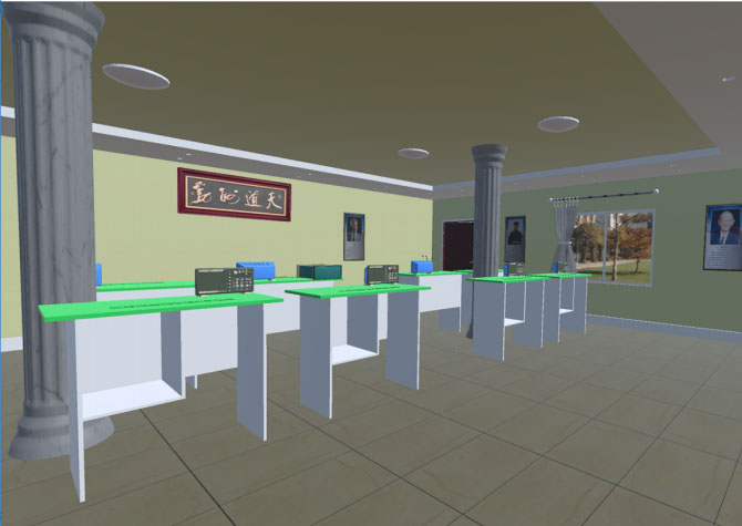
Instrumentation and components scene on the experimental table.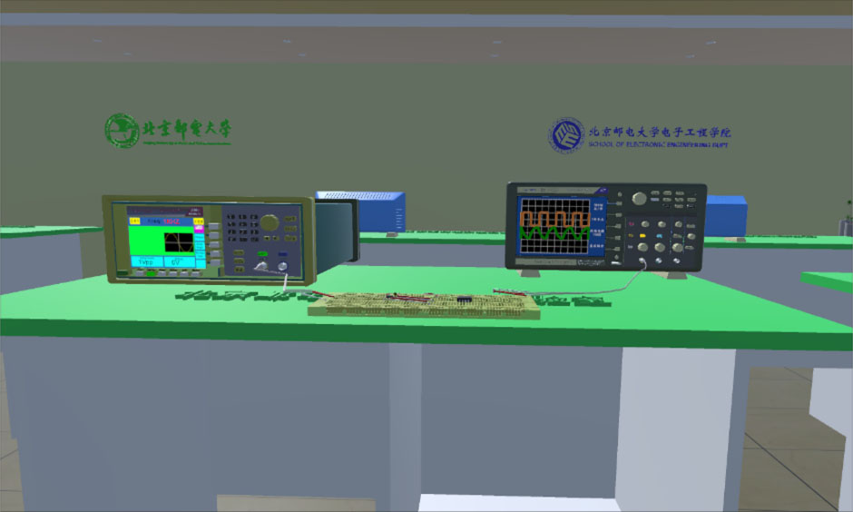
The function realization of virtual instruments and components is the basis of virtual experiments. The system is abstracted into a mathematical modeling model based on the functions and characteristics of general instruments and components itself, and realize the instruments and components by high-level programming language. For function signal generators, oscilloscopes and other instruments and components such as resistors and capacitors, the component modular development method is adopted, and the C# language in Visual Studio is used to develop the functions one by one.
Design of function generator
The function generator in the virtual laboratory is modeled in real proportions based on the Tektronix ATG1602 function generator.
In terms of realizing functions, the function generator are hierarchically divided according to the key operation, and the related key functions are developed. The screen of the function signal generator refreshes in real time to display the relevant parameter information of the output waveform.
Switch. It is located at the top layer of the signal source function. Parameter are initialized when the key function is triggered. When the function signal generator is turned off, the screen is black; when it is turned on, it displays a bright screen state and displays a boot animation. Waveform selection. It is located on the second layer of the signal source function. It sets the waveform control variables. By triggering different waveform selection keys, different waveforms are generated corresponding to different parameter values. For different waveforms, it can be set to sine wave, square wave, triangle wave. Waveform parameter selection. It is located on the third layer of the signal source function. It sets the waveform parameter control variable. By triggering different waveform selection keys, different parameter values correspond to different parameter functions. The amplitude, frequency and offset can be changed. At the same time, the waveform parameter selection key also serves as the unit selection key. On the function signal generator screen, the currently input waveform parameter value can be displayed in text mode. Keypad input. It is located on the fourth layer of the signal source function. After selecting the waveform parameters to be changed, click the small keyboard to pop out the input interface. Each numeric key of the keyboard is assigned a value, the weight corresponding to the current value is determined according to the input order, and the real-time keyboard value is assigned to a variable to save. Select the unit through the waveform parameter selection key to complete the change of the waveform parameters. Screen. Most of the content of the function signal generator’s screen is relatively fixed. The system stores different texture maps, and correspondingly calls different texture maps in different situations. Parameters such as waveform frequency, peak-to-peak value that change in real time are displayed in text mode. The text content can be changed at any time, showing the current output signal information at any time.
The oscilloscope in the virtual laboratory is modeled in real proportions based on the Tektronix MDO3022 oscilloscope.
The oscilloscope functions are also hierarchically divided according to the key operations, and the related key functions are developed. However, the screen display of the oscilloscope is the most important window for observing the output data throughout the experiment, so the Vectrosity plug-in is used to display the signal waveform.
Switch. It is located on the first layer of the oscilloscope function. Parameter are initialized when the key function is triggered. When the oscilloscope is off, the screen is black; when it is on, the screen is bright, and the boot animation is displayed when the power is turned on. Amplitude and time base adjustment knob. The amplitude and time base adjustment knob is the most important function knob of the oscilloscope. The parameters of the waveform expression are changed by changing the state of the function knob. At the same time, the units of the corresponding vertical sensitivity and horizontal time base will also change accordingly. Trigger knob. The correct trigger source selection and trigger level selection of the oscilloscope are the prerequisite adjustments for whether the waveform can be displayed stably. The status of the function knob can be used to change whether the waveform is displayed stably to achieve the trigger adjustment function. Menu button. After the menu button is triggered, the peak-to-peak of waveform, frequency, and unit values of the coordinate axis can be displayed. Screen waveform display. The oscilloscope’s screen consists of a basic grid coordinate graph plus a waveform and text display. The oscilloscope is used to clearly display the waveform and its related information. The grid coordinate map is made by texture mapping, and the waveform curve is drawn in real time using the Vectrosity plug-in. The Vectrosity plugin creates a VectorLine type line object and calls the Draw3DAuto function to draw the described expression in three dimensions. When displaying a new waveform, the Destory function can be used to destroy the old waveform. The text data displayed on the oscilloscope screen, such as the vertical sensitivity, horizontal time base, and peak-to-peak value of each channel, is presented as text variables in the GUI, and will change dynamically as the parameters change. X-Y mode button. X-Y mode can be selected when the oscilloscope channel 1 and channel 2 are open. Through X-Y mode, the phase difference between signals of the same frequency can be measured by Lissajous-Figure method. The phase difference between the input signal and output signal of the first-order RC circuit can be measured in the virtual laboratory. Electrical level trigger knob. Display the level trigger line during operation and select the size of the trigger level.
The resistor and capacitor in the virtual laboratory is modeled based on common axial-lead resistors with electronic color code and monolithic ceramic capacitor.
As a basic component, the function of resistance and capacitor is mainly related to its resistance value or capacitance value. Experimenter can trigger the resistance value or capacitance value setting keyboard through the handle, the resistance value or capacitance value required is input through 3D-keyboard. When setting this parameter, each keyboard numeric key is assigned a value, the weight corresponding to the current value is determined according to the input order, the keyboard value is generated in real time. After selecting the unit and clicking confirm, the final resistance or capacitance value is generated and saved in the corresponding component parameters.
Design of DC power supply and Multimeter
The DC power supply in the virtual laboratory is modeled in real proportions based on the SUING SS2323 DC power supply.
The Multimeter in the virtual laboratory is modeled in real proportions based on the UNI-T UT804 Multimeter.
The screen display of the DC power supply and multimeter adopts digital tube font. As shown in Fig. 6 below.
DC power supply and Multimeter.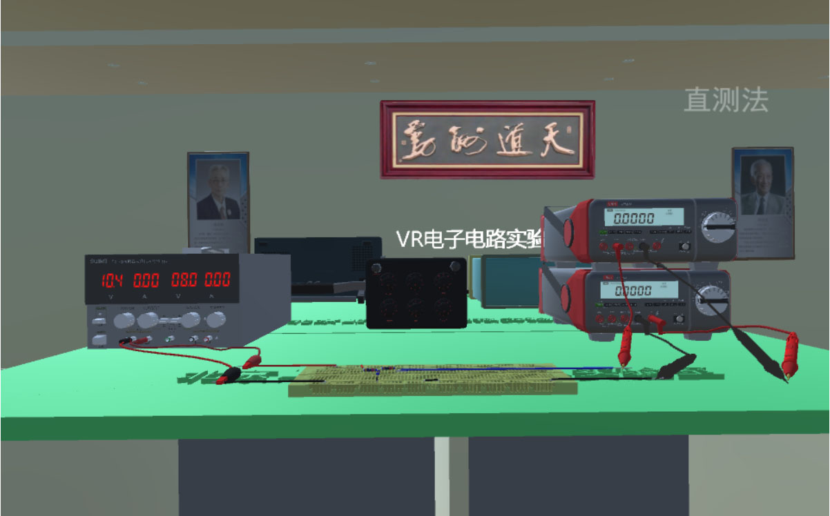
The virtual laboratory system uses the VR device Vive handle as the main interaction tool. The buttons in the handle are used for related operation control. The laser point of the handle is used to confirm the focus. At the same time, the location information of the Vive head-mounted device is used to provide friendly human-computer interaction effect.
Controller interaction design
After the user enters the laboratory system, the functions of human-computer interaction are realized through the Vive handle. The Menu key in the handle acts as a menu key to control the display and disappearance of the menu; the TouchPad key enables the user to move back and forth, left and right, instead of the user’s own real movement; the Trigger key is set as the confirmation key, when the handle laser shoots the object that needs to be interacted, press the Trigger key can realize the function of the object; the Grip key functions as a counterclockwise rotation when the oscilloscope knob is rotated, and the Trigger key functions clockwise. While accessing the virtual laboratory on web, user interact with system by mouse and keyboard.
Experiment content operation menu interaction.
Since the current gesture recognition and sensing functions are not yet mature, in order to make it easier to operate the key knobs of instrument, the laser mode of the handle is used. When the laser emitted by the handle hits the button or knob to be operated, the collision function is used to detect it. After detecting the collision, highlight the button or knob and generate a voice reminder. At this time, press the trigger button of the handle. Unity 3D obtained the information that the handle confirmation button is pressed, which means that the knob is pressed or the knob is rotated clockwise (pressing the grip key at this time means that the knob is rotated counterclockwise), as shown in Fig. 8.
Virtual oscilloscope amplitude knob control.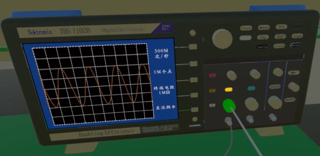
While accessing the virtual laboratory on web, user operate the instruments by mouse and keyboard. Left click represents the confirm button. Pressing the keyboard Z plus a left click represents rotating the knob counterclockwise. Pressing the keyboard X plus a left click represents rotating the knob clockwise.
In the circuit experiment, because the actual connection of the circuit and the connection of the instrumentation probe are complicated to operate in a virtual environment, a fixed circuit connection method is used. For example, in the first-order RC differentiation and integration experiments, you need to adjust the electronic device by laser alignment and press the OK key. Then a keypad for adjusting the device parameters appears. You can change the resistance or capacitance of the device arbitrarily through the keypad. As shown in Fig. 9, the resistance value parameter changes. In addition, when the handle laser point is aligned with the resistor and the grip key is pressed, the circuit can be changed into a differential circuit, and when the handle laser point is aligned with the capacitor and the grip key is pressed, the circuit can be changed into an integrating circuit.
While accessing the virtual laboratory on web, user can set the parameter of circuit elements by left click the resistor and capacitor. User can also switch the integral and differential circuit by pressing the keyboard E.
Virtual oscilloscope amplitude knob control.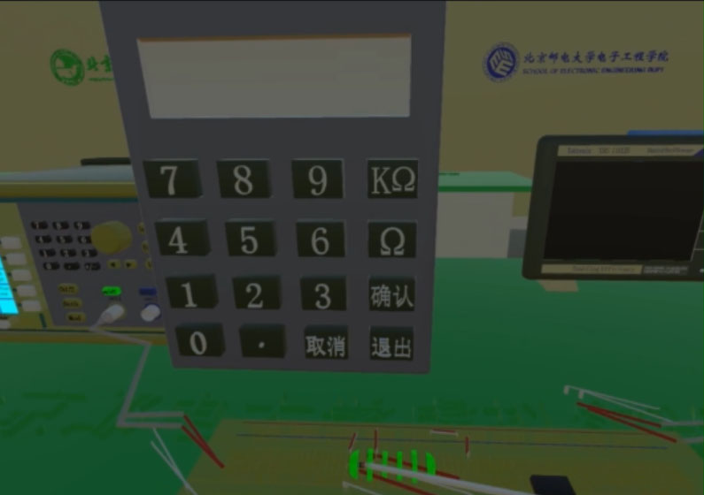
Circuit model.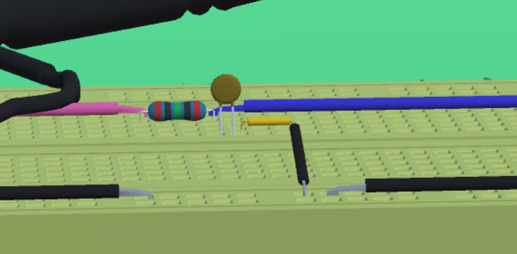
The efficient help guide will reduce the cost when users learning this system. The system provides multi-faceted help to ensure that users can smoothly use virtual instruments and complete related experiments. When entering the laboratory for the first time, there will be experimental interaction methods and experimental content descriptions to help users quickly understand the function and usage methods of the system. After entering the selected experiment, you can watch the homemade experiment teaching video on the big screen. The experimental teaching video demonstrates the entire basic operation of the current experiment and the correctly generated experimental results, which can be used by beginners to learn in depth and teach.
Design of the menu
The system interface design should be concise, clear navigation, fresh colors, and highlight the importance. In this system, the menu is displayed by clicking the menu key. The menu displays in front of the experimenter and will not be blocked by other objects. Users can select one in different experiments, such as basic electronic circuit waveform observation experiment and first-order RC circuit experiment. Users can also exit the experiment through the menu, as shown in Fig. 7.
Teaching videos for experiments
The experimental teaching video uses video recording software to record the standard experimental content steps and precautions. After that, we add corresponding explanations according to the video content and create audio files. In the later period, Premiere was used for editing and commentary. After rendering, it was imported into Unity 3D through QuickTime.
The video playback control in the system uses the method of Movie texture to play the video. By setting the video state variable, use the switch statement to control. And different experiments call different video and audio sources. The video can be started and ended by the video key, and paused and played by the pause key.
Design of experimental content
Based on the development of instruments and electronic components based on virtual reality technology, related experimental content of electronic circuits is designed, including the use of commonly used instruments and meters, first-order RC differentiation and integration circuits, adder circuits, and filter circuits. The electronic circuit experiment content operation menu is shown in Fig. 7, and the experiment flow is shown in Fig. 11.
Experiment content flow chart.
In our virtual laboratory, in order for students to observe the output waveform of the virtual circuit, we designed following steps.
Flowchart of RC circuit waveform output function.
Calculate the period length ( One grid of the virtual oscilloscope is 1.85 cm. While drawing a waveform on the oscilloscope, the waveform is composed of 100 points per grid on the oscilloscope. The interval of these points is Calculate the number of quantization points required for one period of the signal.
Obtain the corresponding expression according to the voltage across the capacitor.
The expression is an exponential function. It is related to input signal frequency Finally, according to the number of quantization points (num_period), call the drawing function of the Vectrosity plug-in to connect the discrete points into a smooth curve. The above process is suitable for RC integrator circuit. While calculate the output waveform of RC differential circuit, simply take the input signal voltage minus the voltage
The design framework of RC circuit waveform output function is show in Fig. 12 below.
Software and hardware environment for system testing
The virtual laboratory software on PC uses HTC VIVE as the terminal display device, the required computer hardware configuration is as follows.
Configuration of test platform
Configuration of test platform
The virtual laboratory software on Web are accessed through browser on PC and it does not support mobile access currently. Because the scene is large and the loading time will be long, it is recommended to use a higher performance CPU and a larger RAM PC.
The virtual laboratory software on PC runs on the Windows platform. Install SteamVR software on the PC, and run the system executable file after connecting the VR device. The configuration of test platform is shown in the Table 1. Users can wear VR equipment, including Vive Pro head-mounted display, and use the handle to carry out experiments easily. Figure 13 is a scenario in which a student carries out a virtual experiment of an electronic circuit using the system on PC.
The virtual laboratory software on Web runs on server and can be accessed through browser. Our virtual laboratory is developed based on unity. Because unity ultimately generates “webgl” files, we recommend a Google browser or Microsoft Edge9 compatible with “webgl” files. Figure 14 is a scenario in which a student is doing virtual experiment on web.
Students use the system for virtual experiments.
Students do virtual experiment on Web.
Signal source frequency setting.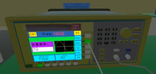
First-order RC integration circuit output.
First-order RC differential circuit output.
Learning how to use instruments is the basis of electronic measurement and electronic circuit experiments. The experimental content designed for the use of basic instruments in this system includes: signal source waveform selection, signal source waveform parameter adjustment, arbitrary waveform output signal from signal source, the stable display of the signal measured by oscilloscope, the peak-to-peak value of the signal measured by oscilloscope, the period and frequency of the signal measured by oscilloscope, and the phase difference of two signals measured by oscilloscope. As shown in Fig. 15 are the frequency settings of the signal source. Through the above experimental content, users will be proficient in the use and operation of instruments.
Electronic circuit experiment test
Take the first-order RC differentiation and integration circuit in the electronic circuit experiment as an example. For the first-order RC circuit connected through a breadboard as shown in Fig. 9. Adjust the signal source output 10 KHz waveform with peak-to-peak value of 1 V. The resistance value of the resistor is set to 10 K
Analysis of VR simulation data
Electrical model of the circuit in the experiment
Since the electronic circuit experiments used in general teaching only need to work at low frequencies, the parasitic parameters of the capacitance and resistance have limited influence. So the resistance and capacitance in the virtual experiment use ideal physical models. By obtaining the signal frequency values, peak-to-peak values, bias values, duty ratio and resistance capacitance values set in the function signal generator, the corresponding parameter conversion functions are written to convert these values into the parameters needed to draw the output waveform and finally the Vectrosity plugin is called to draw the output waveform on the oscilloscope screen.
Data comparison and analysis
The test data of differential circuit and integral circuit in first-order RC circuit are analyzed, and the simulation results of VR electronic circuit are compared with the simulation results of Multisim.
Firstly, the values of resistance and capacitance in the integration circuit are 1 k
Comparison of Multisim and VR system integral circuit simulation results.
Comparison of Multisim and VR system differential circuit simulation results.
For the values of the resistance and capacitance in the differential circuit being 1 k
In RC circuit, we fix the value of capacitance to 1 uF and peak-to-peak value of input square wave to 1 Vpp, then vary the value of resistance and frequency of input signal to compare our simulation algorithm with Multisim simulation software in low frequency circuit. The comparison result is shown in Table 2 below.
Comparison between the output signal of Virtual Laboratory and Multisim
As for the virtual laboratory on Web, from March to July in this year, 1,219 IP addresses from 31 provinces across China conducted a total of 5,184 online experiments through it.
Most of comments from users are positive. The students commented: “It feels very good and the operation is very fast”, “Very novel learning method, very interesting”, “Looking forward to the experiment in the next class”, etc.
Conclusion
This paper develops a VR simulation laboratory with electronic circuit experiment as its core function based on unity3D. In order to balance immersion and promotion, we have been developed the virtual laboratory both on PC and Web. For the virtual laboratory on the PC, users use HTC VIVE to get a VR experience and use the handle as interactive devices; For the virtual laboratory on Web, people use mouse and keyboard as interactive devices. As for the virtual laboratory on PC, it has a stronger sense of immersion, while that on web pays more attention to the ease of operation. Experimenters can use interactive devices to build circuits, set component parameters, operate instruments, and use oscilloscopes to observe circuit output waveforms and other experimental data in the virtual laboratory. It has been verified that in the low-frequency circuit, the simulation results of the virtual laboratory and that in the simulation software are similar.
The VR electronic circuit laboratory provides students with a good learning and testing environment. Students can test what they have learned in class and learn about engineering theory in the VR electronic circuit laboratory. In addition, the VR electronic circuit laboratory allows students to perform different basic electronic circuit experiments at their convenience, and it is no longer necessary to arrange an administrator to monitor the safety of the instrument like the traditional electronic circuit laboratory, which greatly reduces the risk and time [14].
Footnotes
Acknowledgments
This research is supported in part by Teaching Reform Research Project of BUPT (No. 2020CXCY05) and Teaching Reform Research Project of BUPT (No. 2018KC-C04).