
Abstract
A finite element model (FEM) of the bracket arm of wrecker is developed and the mechanical behavior under six representative conditions is studied in this paper. Stress test experiment is carried out to validate the presented FEM. Comparison analyses show that results predicted from the FEM are in good agreement with those obtained from the test experiment. Moreover, the mechanical behavior analyses also give the danger working conditions for each component of the bracket arm. Based on the stress distributions under the danger working condition, structural improvement is conducted for the component which is prone to material failure. Mechanical behavior analyses of the improved structures are also carried out in this paper. Numerical analysis results show that the maximum stresses of each improved component of the bracket arm are all reduced to close or below the allowable stress. This indicted that the load bearing capacities of each component are improved effectively and meet the requirements of engineering applications.
Keywords
Introduction
Wreckers are a class of important and useful special rescue mechanical equipment. The main function of them is to lift or tow the accident or illegal vehicles from highway and city roads. It plays a significant and meaningful role in modern traffic management. Moreover, wreckers are also widely applied in other areas such as mining, agriculture and transportation etc. [1, 2].
Bracket arm is an important working device of the wrecker except for boom and its main function is to lift and drag the defective, illegal and other type of vehicles [3]. The geometry structure of the bracket arm is similar to the boom which has becomes a typical engineering structure and its mechanical beahvior has been studied by many researchers [4]. The main characteristic of the bracket and boom is that they are all representative telescopic structure and they are usually driven by hydraulic cylinder. The relative movement of the telescopic structure occurs between the slider fixed on the arm and the inner surface of the adjacent arm. The main load applied on the bracket arm is the gravity of the dragged vehicles, which can be taken as the concentrated force acted on the terminal of the bracket arm and it is also similar to the boom. The similarity of the geometry structure, movement mode and loading mode will lead to the similar bearing mechanism. The research contents of the above typical telescopic structure studied in the open literatures can be divided into three categories, i.e. the study of bearing mechanism, the study of contact and friction mechanism and the structure optimization and lightweight design [5, 6, 7, 8, 9]. Considering the function and bearing mode of the bracket arm, the bearing capacity is one most of important factor to evaluate the performance of the bracket arm and determine the service-life and working security. Based on three dimensional (3D) geometry modeling software of Solidworks and numerical simulation software of Ansys Workbench, the stiffness and strength of the bracket arm of the flat repair car have been studied. Moreover, structural optimization under traditional experience design was carried out to improve the bearing capacity [10]. Similarly, mechanical behavior of a bracket arm assembly of wrecker was simulated [11, 12]. The geometry model of bracket arm assembly was established by using UG software and mechanical behavior analysis was implemented through NX Nastran software considering the actual working condition. Numerical results shown that the strength of the bracket arm is enough for engineering requirement under the two typical conditions of all arms stretched and all arms retracted. Taking the lift arm of mining wrecker as research object, stiffness and fatigue life were studied by using finite element method [13]. Moreover, topology and size optimization were also conducted to improve the bearing capacity and fatigue life. Analysis results shown that the performances of the optimized structure were improved greatly. The above works predict the mechanical behavior of the wrecker bracket arm by using the mechanics theory and finite element method. The general characteristics of the bearing capacity have been predicted effectively. However, these works are only in the stage of the theoretical analysis. The proposed models and numerical analysis results have not been validated. Thus it has not directly used for engineering applications. Combining with finite element method and test experiment, Li et al. [14]studied the structural strength and stiffness of the lifting device (bracket arm) of wrecker under the full extension and full retraction conditions. Comparison analyses shown that the maximum error between results predicted from finite element model (FEM) and those obtained from stress test experiment was less than 10%. Only few small local regions occurred the phenomenon that the stress exceeds the yield limit. This indicated that the bracket arm analyzed in this paper met the engineering application requirements. In this work, the rigid contact was used to simulate the contact and friction behavior occurred between adjacent arms. Sun et al. [15] developed a FEM of the bracket arm of road wrecker under six typical working conditions. Static analysis was conducted and strength and stiffness of the bracket arm were predicted. Stress test experiment was also carried out to validate the proposed model. By comparison with test data, numerical results shown good agreement with those obtained from the stress test. Xie et al. [16] analyzed the structural strength and stiffness of the vertical basic arm of the bracket arm under the full load working condition by using finite element method. Based on the distributions of stress and strain, lightweight optimization was also carried out. Simulation results shown that the weight of the optimized structure reduced nearly 22.14%. Based on analytical method and finite element method, the mechanical behavior of the bracket arm of a heavy wrecker were studied [17]. The forces acted on the pins and stress distribution of each component of the bracket arm were deduced and predicted. In order to validate the model, stress test experiment under the typical working condition was carried out. Comparison analyses shown that results predicted from FEM were in good agreement with test data. Furthermore, structural improvement was also conducted in this paper and good results had achieved for engineering application. From the above literatures it can be observed that the load bearing capacity and structural improvement and optimization have been studied in detail with the help of the computer-aided design method and finite element method. However, it should be pointed that there are still some problems existed in the works. In order to reduce the analysis difficulties, some important factors such as contact, friction and sliding between two adjacent telescopic arms, material plasticity and slider material property have not considered in the proposed models. Moreover, the analyzed working conditions are relatively few. Lastly, the structure improvement studies are relatively seldom.
The contribution of this study can be summarized as follows: 1) a 3D parametric solid FEM of the bracket arm is developed by using the Ansys parametric design language. The factors of contact, friction, sliding and material plasticity have been considered in the proposed model. 2) six typical working conditions of the bracket arm are considered and the danger condition can be determined. Moreover, the stress distribution and the load bearing capacity of the bracket arm can be predicted by using the finite element analysis. 3) based on the simulation results, the structure improvement is also implemented and better load bearing capacity can be achieved. This establishes good foundation to study the complex mechanical behavior under complex working conditions.
The rest parts of this work are organized as follows: the FEM of the bracket arm of the wrecker is developed in Section 2. The stress test experiment, model verification and the mechanical behavior analysis for the original structure of the bracket arm are described in Section 3. The structure improvement of the bracket arm and the mechanical behavior of the improved bracket structure are carried out in Section 4. Finally, the conclusion of the work is given in Section 5.
Finite element model
Element and modeling process
A FEM of the bracket arm of the wrecker and its main components are shown in Fig. 1. The down-to-up process of modeling is used and the geometry topology of each component has been elaborately planned. This ensures each component of the bracket arm has excellent meshing grids. Moreover, the geometry structure and grid density are all parameterized and they can easily be controlled by program. This effectively shortens the modeling and analysis period after the initial model has been established.
FEM of the bracket arm of wrecker.
ANSYS software is used through all the model establishment and mechanical behavior analysis. 3D high-order solid brick element (Solid186 for ANSYS) is used for structural discretization of main body, including vertical basic arm, vertical telescopic arm, horizontal basic arm, horizontal 1st telescopic arm, horizontal 2nd arm, swing arm and connecting frame pin. This element is defined with 20-node with three degrees of freedom per node and is able to simulate elasto-plasticity, stress stiffening, large deformation and large strain. In addition, this element has secondary displacement mode, which makes it more suitable to discretize the complex geometry boundary. The total number of this element of the bracket arm is 52104 and the number of nodes 80467. 3D tension-compression link element (Link8 for ANSYS) is adopted for simulation of variable amplitude cylinders and telescopic cylinders used between vertical and horizontal telescopic arms. This element is a uniaxial tension-compression element and is defined with two nodes, each having three degrees of freedom. Moreover, this element can be used to model trusses, cables, links, springs, etc. Surface-to-surface contact elements (Conta174 and Targe170 for ANSYS) are used to simulate the contacts occurred between contacting sliders and arm surfaces which belongs to two adjacent telescopic arms respectively as shown in Fig. 1. Conta174 elements are covered on the surfaces of the slider 3D solid brick elements, while the Targe170 elements are applied on those of the contacting telescopic arm. The elements are capable of simulating the contact, friction and sliding behavior occurred between two contacting surfaces. Coulomb frictional sliding law was assumed and penalty algorithm was applied. When the contact and the target surfaces penetrate each other numerically, contact behavior occurs and contact properties can be simulated.
In order to facilitate modeling process, auxiliary coordinate systems including global coordinate (
The material of steel plates used for the bracket arm is Q690. Its material property parameters are listed in Table 1. The von Mises yield criterion was assumed. An elastic-plastic material model with the bilinear isotropic hardening relationship was adopted in the simulation analysis. The allowable stress can be derived from the following equation.
where,
Material property parameters of steel plates
Material property parameters of steel plates
The material used for sliders is copper. Its material property parameters and the friction coefficient between the arm and slider are all listed in Table 2. An elastic material model with linear isotropic hardening relationship was used in this analysis.
Material property parameters of sliders
Representative conditions selected for the finite element analysis are shown in Fig. 2. The conditions are defined by the variable amplitude angle (
Representative working conditions for finite element analysis.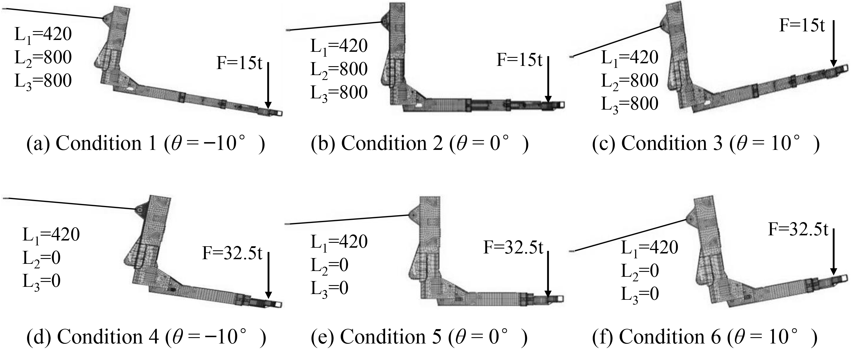
Pin connections between rotating members are simulated by using shaft-through method [18]. This method is capable of effectively dealing with the contact problems between shaft and hole and reducing the model size without effects on analysis accuracy.
The displacement degree of freedoms of the connecting frame pin and the pin of vertical telescopic arm used to connect the wrecker frame are all fixed in nodal
In order to ensure the accuracy of the proposed model, the convergence study is carried out in this paper. Three FEMs of the bracket arm with different mesh density are achieved by adjusting the mesh parameters embedded in the modeling program. The 1st FEM has the initial mesh density, which is shown in Fig. 1. The 2nd FEM has the two times of the mesh density of that of the 1st FEM. Similarly, the 3rd FEM has the three times of the initial mesh density. Under the condition 2 shown in Fig. 2b, finite element analysis is conducted and the maximum equivalent stresses (MES) of each main component can be predicted. The numerical simulation results are listed in Table 3.
MES of each bracket arm component with three different mesh density (MPa)
MES of each bracket arm component with three different mesh density (MPa)
It can be observed from this table that the numerical results of the MES of each bracket arm component, which are predicted from the 2nd and the 3rd FEMs, are in good agreement with the 1st model with the initial mesh density. The maximum error is 0.15%, which occurs in the swing arm. This indicates that the bracket arm FEM with the initial mesh density shown in Fig. 1 has a good calculation accuracy. Thus, subsequent finite element analyses are all conducted on basis of this model.
Stress test experiment.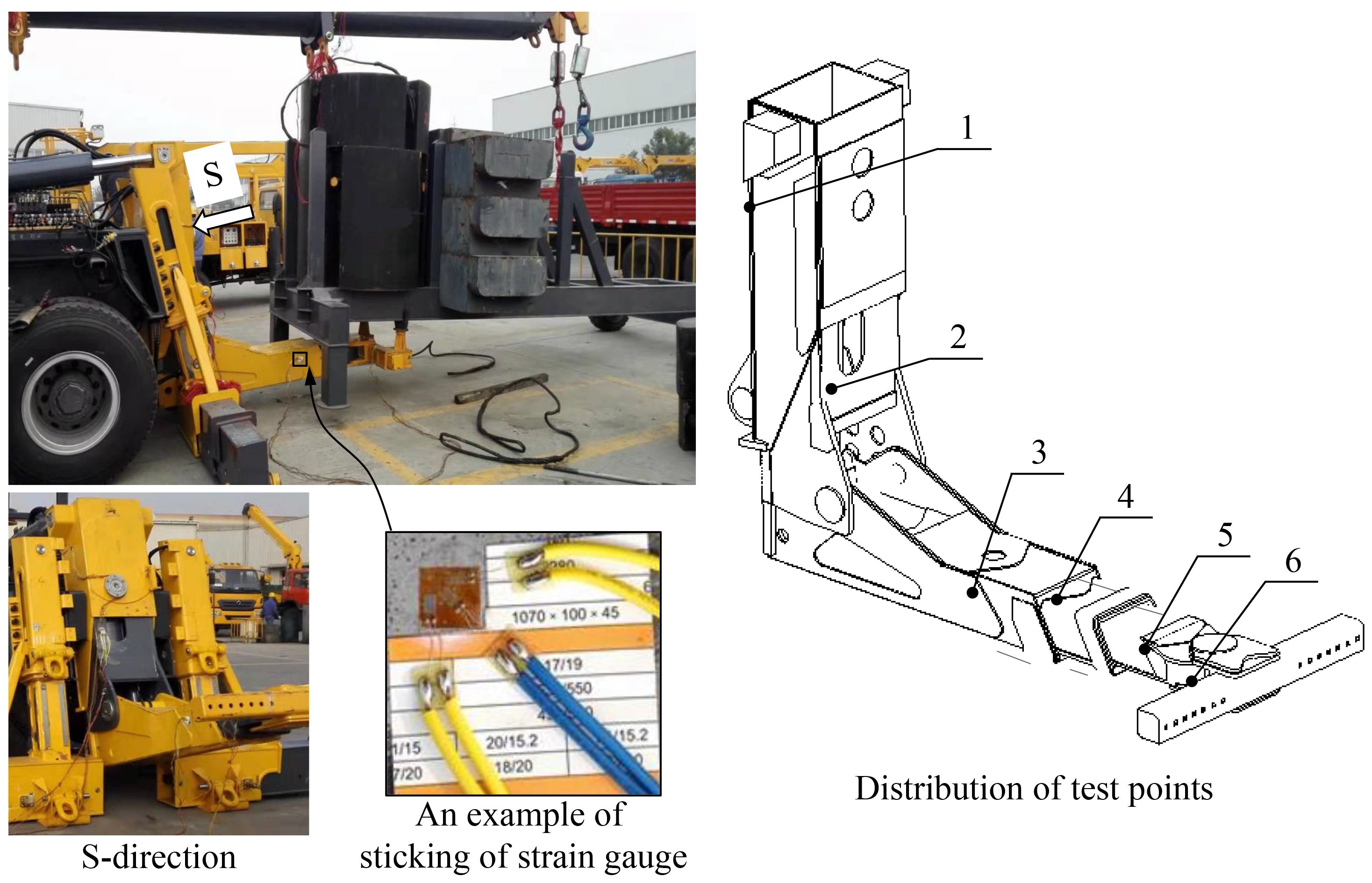
In order to validate the presented FEM of the bracket arm of the wrecker, stress test experiments under the representative working conditions of 2 and 5 shown in Fig. 2 are carried out. The field situation is shown in Fig. 3. The test experiment has been carried out referring to the structure stress test criteria of the earth-moving machinery of China (GB/T 22941.1-2017). The test experiment is carried out in the open air and the temperature varies from 26
In order to improve the accuracy of the test results, the external force load on the bracket arm is increased gradually and slowly. And at least three effective measurements should be conducted under each working condition. The final strain results are the average values of every effective measurement results.
The location distribution of test points is also shown in Fig. 3. Six test points located on each components of bracket arm are selected. The selection principle of test points is to ensure that the stress in the region covered by the rectangular rosette is bigger and has a small change gradient.
Mechanical behavior prediction and results analysis
Stress results obtained from the stress test experiment and those predicted by FEM under the 2nd and the 5th working conditions are shown in Table 4. Moreover, the relative error between the above two type of results for each test point is also given in this table. It can be seen from this table that under the 2nd working condition the maximum stress error between the test results and numerical results is 5.1%, while it is 5.5% for the 5th working condition. Considering the effects of model simplifications and test condition, it indicates that the numerical results are in good agreement with the test results. In other words, the correctness and accuracy of the FEM proposed in this paper has been validated. Moreover, this also establishes a good foundation for the subsequent mechanical behavior analysis and structure improvement.
Stress comparisons between test and FEM
Stress comparisons between test and FEM
The danger condition is defined as a typical condition in which the maximum equivalent stress is bigger than other conditions. The stress status under this danger condition directly determines the load bearing capacity of each component. Thus it is the main research object in this paper. In order to determine the danger condition, finite element analyses of each component under the six typical working conditions have been conducted in the paper. For the vertical basic arm, numerical analyses show that the maximum equivalent stress occurs in the 6th working condition. The distribution of von-Mises equivalent stress under the 6th condition is shown in Fig. 4. It can be seen that the maximum stress is 512.2 MPa which is bigger than the allowable stress, whereas it is only 74.2% of the yield limit. Moreover, the maximum stress occurs in the corner region of the arm, which is obviously bigger than those in other areas. This is the stress concentration which probably is caused by the big change of the geometry structure.
Equivalent stress distribution of the vertical basic arm under the 6th working condition.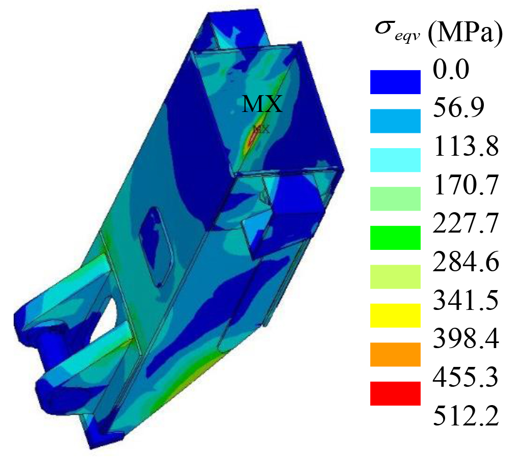
Equivalent stress distribution of the vertical 1st telescopic arm under the 6th working condition.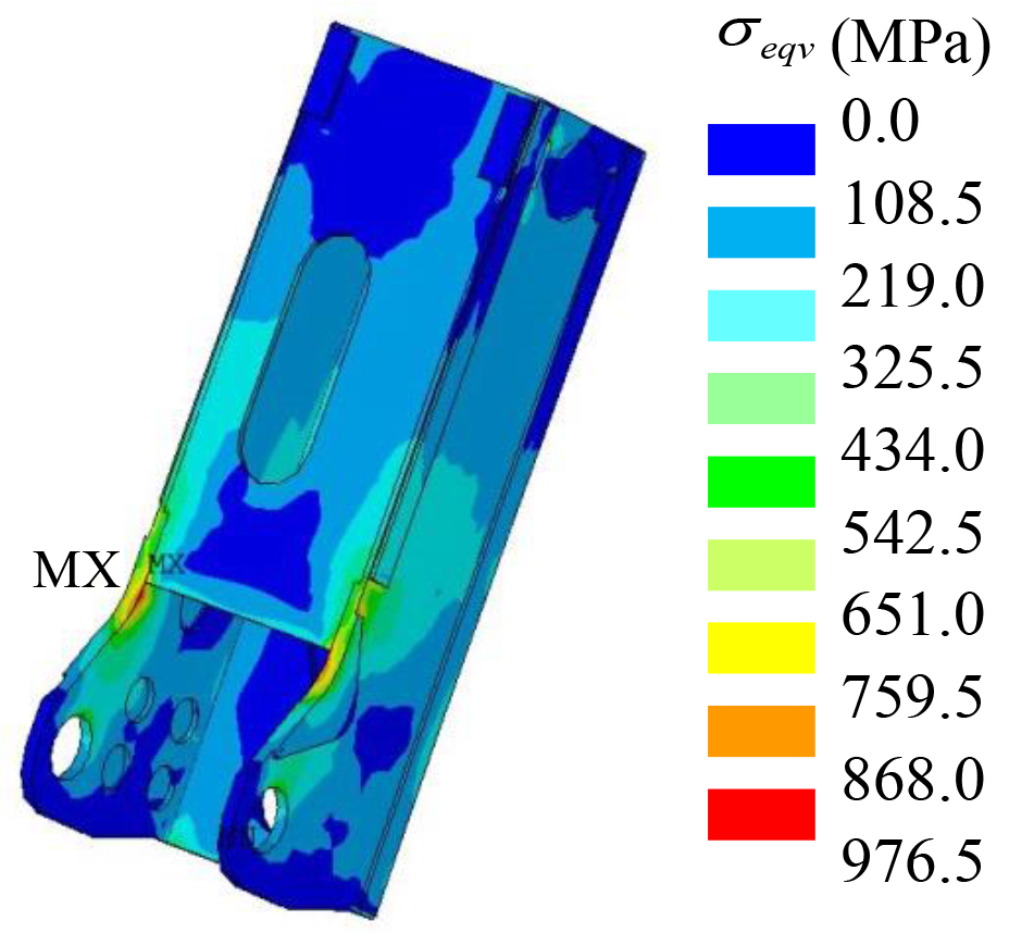
For the vertical 1st telescopic arm, the maximum equivalent stress also occurs in the 6th working condition and its von-Mises equivalent stress distribution is shown in Fig. 5. It can be observed that the maximum stress occurs in the arc transition region of side plate and its value is 976.5 MPa which is larger than the tensile limit. The material has entered into plastic region and its load bearing capacity is decreased even lost and thus the structural improvement is suggested.
For the horizontal basic arm, the maximum equivalent stress in the 1st and 5th working conditions are all bigger than others. The contour plots of von-Mises equivalent stress under these two working conditions are shown in Fig. 6. It can be seen that the maximum stress occurs in the connection region between the slider and the side plate shown in Fig. 6a, while that occurs in the pin hole and the turning region of the side plates shown in Fig. 6b. Moreover, it can be seen that the maximum stresses in these two conditions are all beyond the yield limit and thus structural improved is also suggested.
Equivalent stress distribution of the horizontal basic arm: (a) the 1st working condition; (b) the 5th working condition.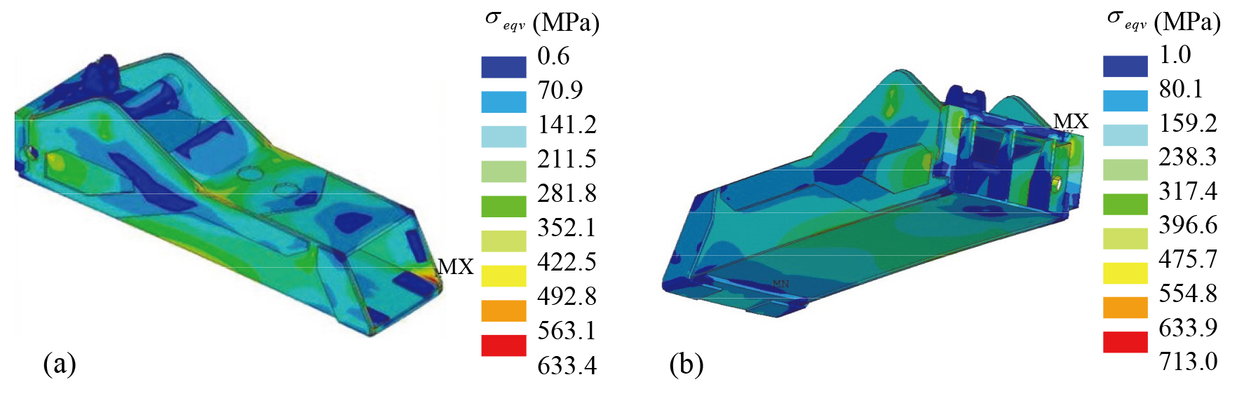
For the horizontal 1st telescopic arm, the contour plots of von-Mises equivalent stress under the 2nd and the 4th working conditions are shown in Fig. 7. It can be seen that all the maximum stresses in these two conditions are bigger than the allowable stress and they are 85.9% and 74.8% of the yield limit, respectively. Although the material does not enter into the plastic region, structural improvement is also suggested as the regions occurred maximum equivalent stress is the main bearing areas.
Equivalent stress distribution of the horizontal 1st telescopic arm: (a) the 2nd working condition; (b) the 4th working condition.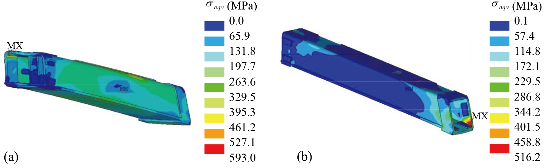
Equivalent stress distribution of the horizontal 2nd telescopic arm: (a) the 2nd working condition; (b) the 4th working condition.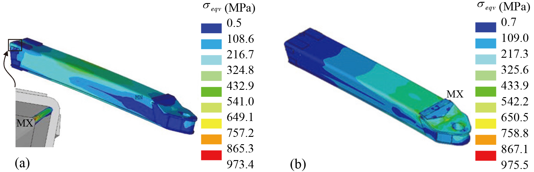
For the horizontal 2nd telescopic arm, the danger condition is the 2nd and the 4th working condition. Contour plots under these two conditions are shown in Fig. 8. It can be seen that the maximum stresses are all bigger than the tensile limit. The bulk of material has entered into plastic region and the load bearing capacity has also been decreased greatly. Thus structural improvement is required for engineering application.
For the swing arm, the danger condition is the 6th working condition and the distribution of von-Mises equivalent stress under this condition is shown in Fig. 9. It can be seen that the maximum is 544.0 MPa which is nearly 78.8% of the yield limit. Moreover, it only occurs in the small local region and this region is not the main bearing area. Thus it has not considered to implement structural improvement in this paper.
Equivalent stress distribution of the swing arm under the 6th working condition.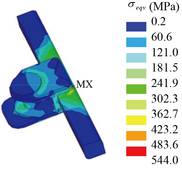
In order to improve mechanical properties of the bracket arm, the geometry structural improvement has been carried out on the basis of the analysis results given in Section 3 and engineering experience. The components which are needed to implement the structural improvement consist of the vertical 1st telescopic arm, horizontal basic arm, horizontal 1st telescopic arm and horizontal 2nd telescopic arm, in which the equivalent stresses in the original structure are all beyond the yield limit.
The structural improvement of the vertical 1st telescopic arm is shown in Fig. 10. Three structural changes are been conducted. Firstly, the transition arc shape and its location on the side plate A are redesigned. Secondly, the shape of the sticking plate B is modified according to the shape of the side plate A. Thirdly, the length of the middle plate C is lengthened.
Structural improvement of the vertical 1st telescopic arm.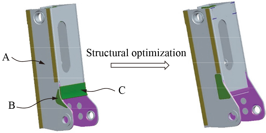
The changes of the horizontal basis arm are shown in Fig. 11. Firstly, the plate width of the upper part of the middle stiffeners D is increased from 50 mm to 85 mm. Moreover, sealing plates are added on its outermost sides. Secondly, the shape of the side plate E is redesigned and six pair of stiffeners D are added at the inner side of the plate E. Thirdly, the location of the sliders F is moved 35 mm away from the left side.
Structural improvement of the horizontal basic arm.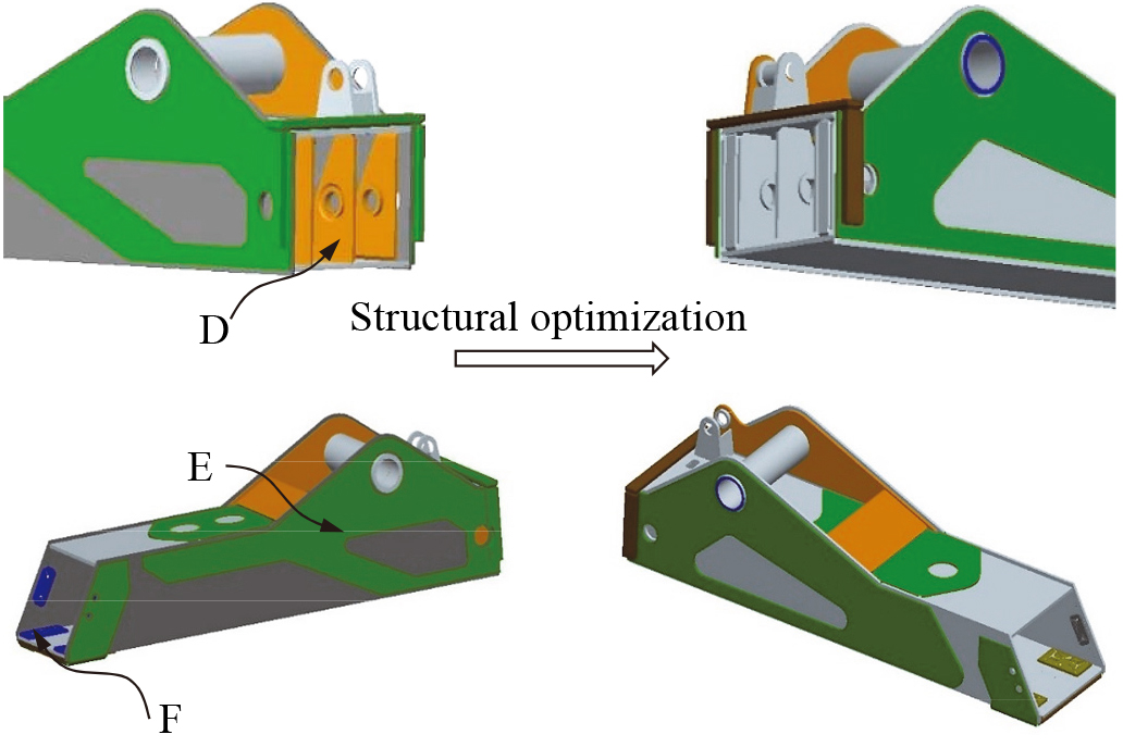
Structural improvement of the horizontal 1st telescopic arm.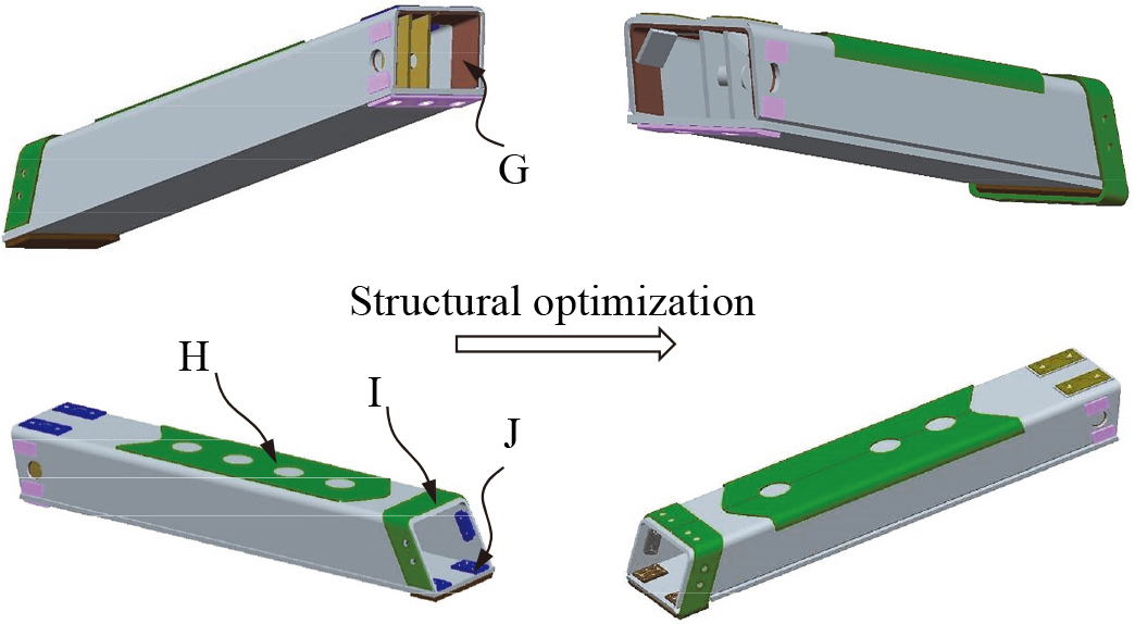
The structural improvement of the horizontal 1st telescopic arm is shown in Fig. 12. Four structure changes have been conducted for this component. Firstly, slanting stiffeners are welded on the turning region of the side plates G. Secondly, the width of the cover plate H is increased to wrap up the fillets. Thirdly, the length of the cover plate I is increased to wrap up the baseplate. Fourthly, the location of the sliders J is moved 15 mm away from the right side.
There are three geometry structural changes in the horizontal 2nd telescopic arm as shown in Fig. 13. Firstly, slanting stiffeners are welded on the turning region of the side plates K. Secondly, the thickness of the cover plate L is increased from 8 mm to 12 mm. Thirdly, slanting stiffeners are added on the both sides of the middle plate M.
Structural improvement of the horizontal 2nd telescopic arm.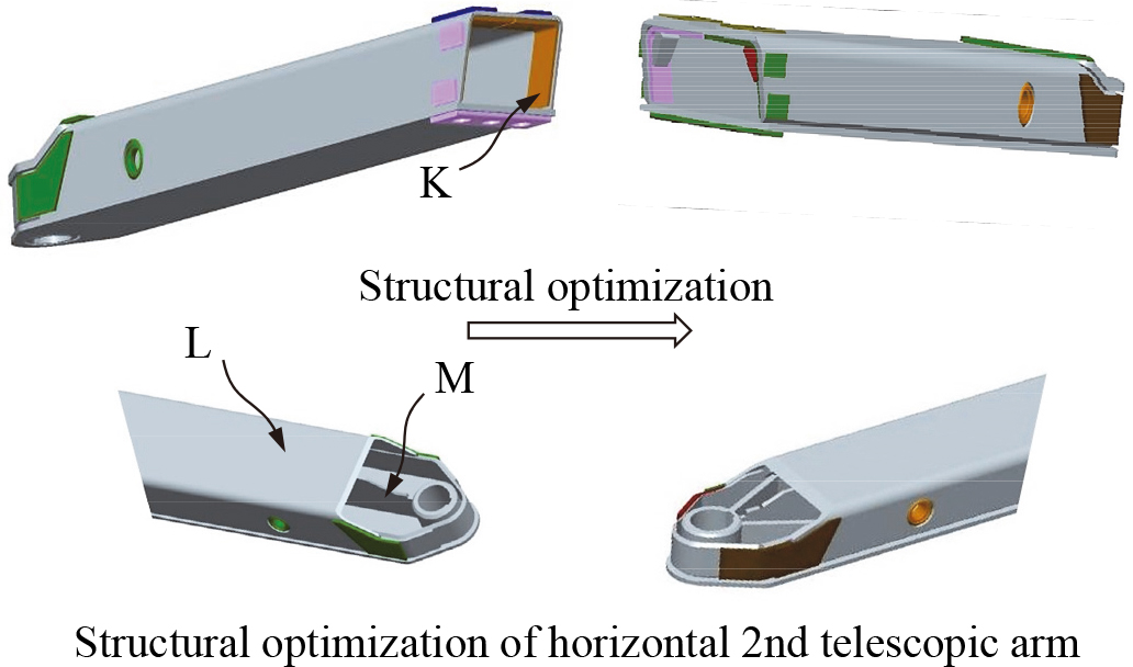
The target of the structural improvement is to decrease the maximum equivalent stress of the bracket arm on the basis of an enough bearing rigidity and strength. Considering the discreteness of the thirteen structural improvements given in the Figs 10–13, the structural improvement process becomes to search for the best combination from all the variable combinations constituted by the thirteen variables. The judgment criterion of the best combination is that the maximum equivalent stress is the least compared with those obtained from all the variable combinations. In order to realize the automation of the searching process, the structure before improvement is denoted by “0” and that after improvement is denoted by “1”. Enumeration method is applied and the searching process is programmed by ANSYS parametric design language. The searching process is presented as follows: 1) the finite element analysis is implemented with one combination of thirteen variables and the maximum equivalent stress is recorded; 2) the step 1) is implemented with another combination of thirteen variables. Then the maximum equivalent stresses recorded from the two adjacent analyses are compared and the smaller one is recorded; 3) the step 2) is conducted repeatly until all the variable combinations have been compared and the least maximum equivalent stress and its corresponding variable combination can be acquired, which is the final results of the structural improvement.
Mechanical behavior of the improved components has also been simulated by using finite element method to check the improvement effects. The distribution of von-Mises equivalent stress of the improved vertical 1st telescopic arm is shown in Fig. 14. The 6th working condition is also selected as the analysis of the original structure. It can be observed that there are still stress concentration and its areas of occurrence are similar to the original structure. However, the maximum stress in the improved structure is 450 MPa, which is smaller than the allowable stress of the material and only 46.1% of that of the original structure shown in Fig. 5.
Equivalent stress distribution of the improved vertical 1st telescopic arm under the 6th working condition.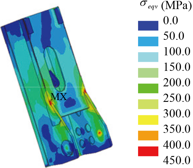
The contour plots of von-Mises equivalent stress of the improved horizontal basic arm under the 1st and the 5th working conditions are shown in Fig. 15. From this figure it can be seen that stress concentration still exists in the improved structure, which is probably determined by load bearing mechanism. Although there is still stress concentration, the stress value has been decreased below the allowance value. Comparison analyses between the original and improved structures show that the maximum equivalent stress in the 1st condition is smaller than the allowable stress and it is reduced 175 MPa. For the 5th working condition, the maximum stress is also smaller than the allowable stress and it is only 60.4% of that of the original structure shown in Fig. 6.
Equivalent stress distribution of the improved horizontal basic arm: (a) the 1st working condition; (b) the 5th working condition.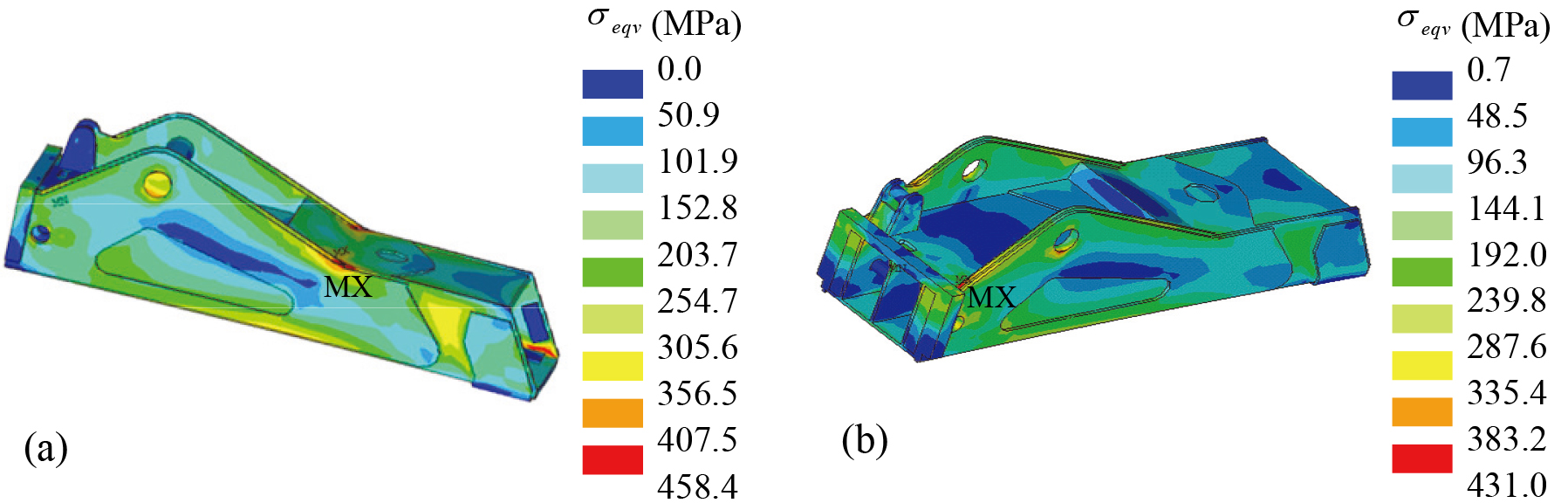
The distributions of von-Mises equivalent stress of the improved horizontal 1st telescopic arm under the 2nd and the 4th working conditions are shown in Fig. 16. It can be seen from this figure that it is similar to other arms that there are still stress concentration occurred in the improved structure. Furthermore, it can also been seen that the maximum equivalent stresses in these two conditions are all within the range of the allowable stress and they meet the engineering requirements.
The contour plots of von-Mises equivalent stress of the improved horizontal 2nd telescopic arm under the 2nd working condition and the 4th working condition are shown in Fig. 17. Compared with the original structure, the maximum equivalent stress of the improved structure has a great reduction. The maximum stress under the 2nd working condition is only 45.5% of that of the original structure, whereas it is 49.2% for the 4th working condition. Although the maximum stress of the 4th working condition exceeds the allowable stress, it is only 69.6 of the yield limit and it occurs in the small location regions of the hole. Thus the structural improvement has reached the redesign purpose and meets the engineering requirements.
Equivalent stress distribution of the improved horizontal 1st telescopic arm: (a) the 2nd working condition; (b) the 4th working condition.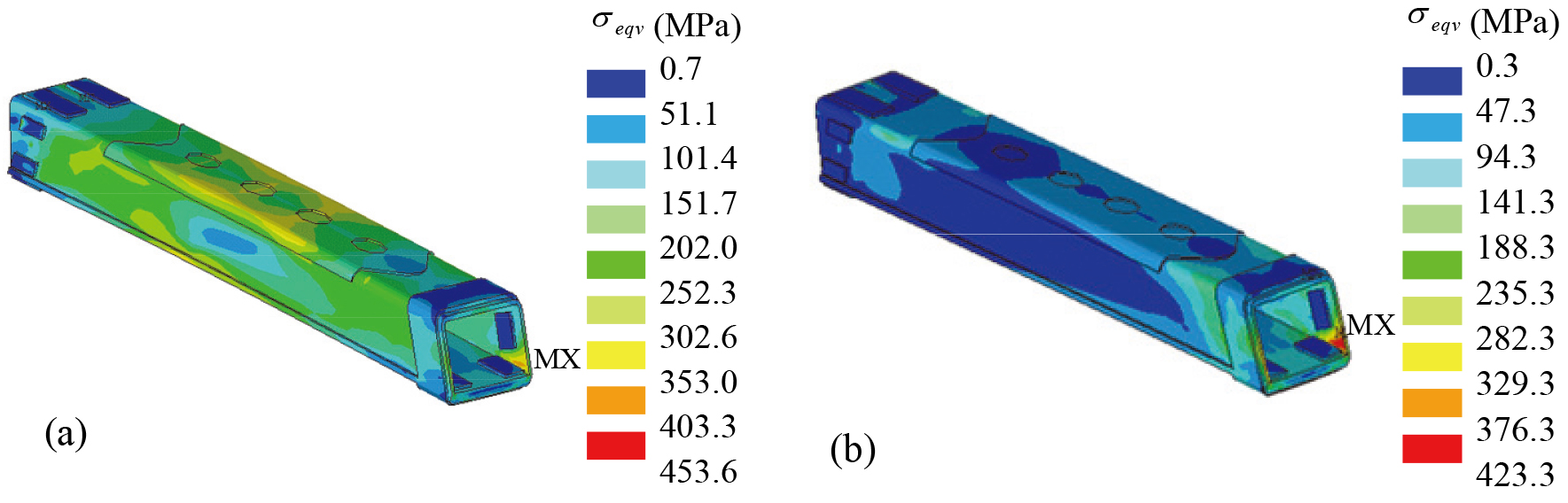
Equivalent stress distribution of the improved horizontal 2nd telescopic arm: (a) the 2nd working condition; (b) the 4th working condition.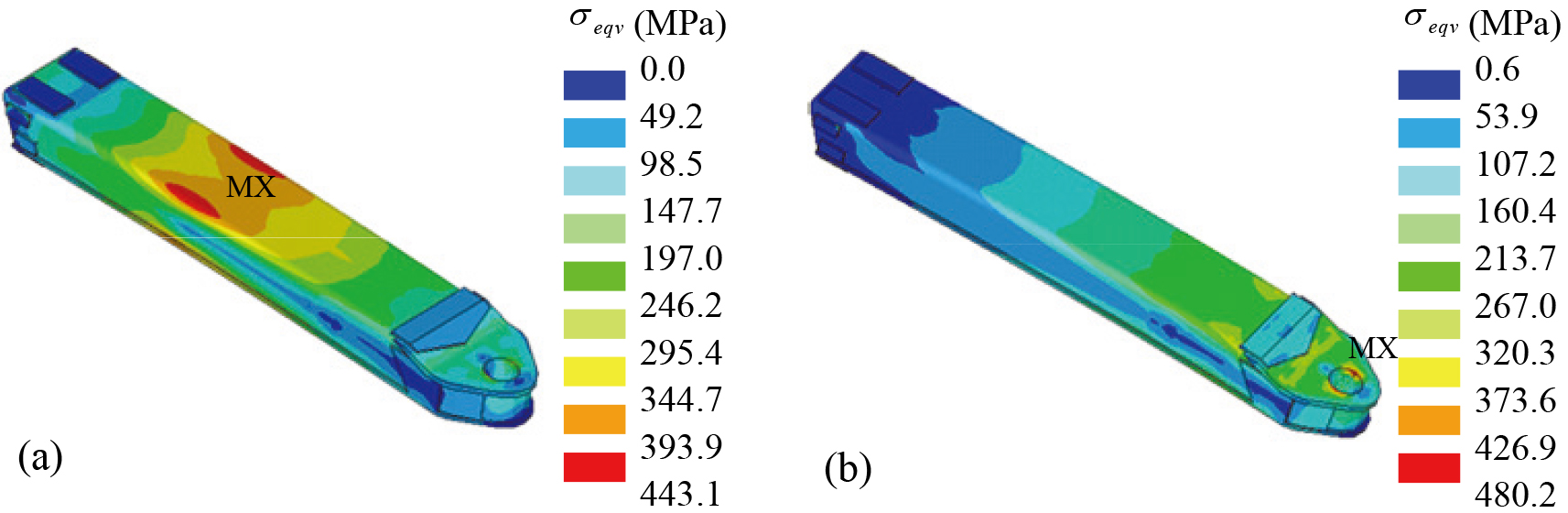
Based on finite element method and test experiment validation, the mechanical behavior analysis and structural improvement of the bracket arm of the wrecker have been carried out in this paper. By comparison with the stress test experiment, the correction of the FEM proposed in this paper has been validated and it calculation accuracy meets the engineering application requirements. Mechanical behavior under six representative working conditions have been studied and the danger conditions for each component have been determined. Based on the stress distribution of the danger condition, structural improvement has been conducted and the mechanical behavior of the improved structures has also been analyzed. Numerical simulation results have shown that the maximum equivalent stresses of the main components of the bracket arm are all reduced below the allowable stress. Only the maximum equivalent stress of the improved horizontal 2nd telescopic arm under the 4th working condition is bigger than the allowable stress. However, it is only 69.6% of the yield limit and occurs in the small local regions of the hole. Thus it can be concluded that the load bearing capacity of the bracket arm has been improved effectively by the structural improvement and the method used in this paper can be extended to other engineering application areas.
Footnotes
Acknowledgments
The authors extend their appreciation to the Project of Shandong Province Higher Educational Science and Technology Program (KJ2018BBH018) and Doctoral Scientific Research Foundation of Zaozhuang University (2017BS05).