



Abstract
A special ceramic roller bearing press (SCRBP) is developed to press two bearings efficiently and precisely at the same time. A speed control mathematical model of the bearing press is built to obtain stability bearing pressing speed. The fuzzy adaptive PID controller of the bearing pressing speed of SCRBP is designed. The simulation model is also built. Fuzzy adaptive PID control is compared with conventional PID control. By simulation analysis, the simulation results show that adjusting time of fuzzy adaptive PID control is short, and its overshoot is very small, almost coincides with the set pressing speed. Moreover, fuzzy adaptive PID is suitable for the pressing speed control of the bearing pressing speed system with step interference signal. The pressing stability speed is obtained by fuzzy adaptive PID control.
Introduction
The ceramic material roller has many advantages, such as high wear resistance and high life span. It is widely used in belt conveyor. Ceramic roller is mainly composed of roll body, mandrel shaft, bearings, sealing rings, etc., as shown in Fig. 1. However, due to high brittleness and high hardness of ceramic materials, the processing of ceramic roller is difficult. The ceramic roller assembly is mainly completed by manual or semi-automatic means, the processing quality and efficiency are low [1, 2, 3, 4]. There are many problems need to be improved. After mandrel shaft is installed in roller body, both ends of the mandrel shaft need an interference pressed bearing to roller body to support the mandrel shaft and meet the requirement of concentricity [5, 6, 7]. The bearing press can be done by assembly equipment, temperature difference assembly, or pressuring-loading with machines, etc. The assembly equipment is to knock the bearing in place, its work efficiency is low. The temperature difference assembly principle is to use the physical properties of the material shaft’s thermal expansion which causes the internal stress and deformation of the materials. This method would affect the assembly accuracy of the parts. Pressure-loading is a popular method of present. Compared with the temperature difference assembly, it is less affected by the environment. Compared with assembly equipment, it has less damage to ceramic body due to the specialized equipment and clamps [8, 9, 10, 11].
Ceramic roller.
Using traditional bearing press machine, only one bearing is pressed to one side of roller body at a time. After the bearing is preloaded, another bearing is pressed on the other side of roller body again. This method needs a long time, also needs to guarantee the precision. Therefore, two pressing machines are often used to press a pair of bearings at one time. They are placed symmetrically on both sides of the roller. However, this method decreases the repeated utilization rate of the equipment and the synchronization accuracy. Moreover, the ceramic roller body is brittle, and the ability to resist impact during bearing pressing is weak, resulting in lower pressing efficiency and pressing accuracy [12]. Therefore, a high-efficiency special ceramic roller bearing press (SCRBP) is designed to press two bearings on both sides against the ceramic roller body at the same time, which is shown in Fig. 2.
SCRBP mainly consists of a bed frame, two spindle systems, and two clamping devices. The spindle system can finish spindle displacement setting, displacement adjustment for push rod of the spindle system, and the ceramic roller mandrel positioning. The clamp device mainly comprises two parts, a roller body supporting mechanism and a mandrel lifting mechanism. After the ceramic roller is supported by the supporting mechanism, the lifting mechanism lifts the mandrel to the center of the roller body, and the pressure rods at both ends of spindle system move to fix the mandrel, and then the lifting mechanism is down to the lowest point to prevent interference when the bearings are pressing. Finally, the spindle moves to press the bearings on the roller body [13]. Pressing bearings process of SCRBP is seen in Fig. 3.
Special ceramic roller bearing press.
Pressing process of the special ceramic roller bearing press.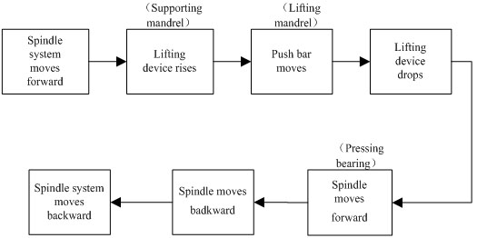
The press speed and its stability of SCRBP directly affect the pressing quality. When the push rod begins to contact with the ceramic roller body, the pressing pressure suddenly increases and changes because of the change of pressing force. As the pressure in the system changes, the leakage of the hydraulic components changes. The leak flow of the speed control system causes the pressing speed to fluctuate. In addition, the increase in the temperature of the hydraulic oil causes the viscosity of the oil to decrease, which also exacerbates system leakage and reduces the pressing speed. The changing pressing speed may increase the friction coefficient and increase the stress of the contact surface, and affect the roller processing accuracy. Therefore, the speed control transfer function of SCRBP is established, and the speed controller based on fuzzy adaptive PID control is designed to obtain stability pressing speed.
Schematic diagram of bearing press speed control system.
Speed control system of SCRBP mainly includes an oil hydraulic pump, an oil hydraulic cylinder, an electro-hydraulic proportional control valve, a speed sensor, a data acquisition card. The system control schematic is shown in Fig. 4. The pipeline of the whole hydraulic system is short and thick, so the friction loss inside the pipeline, the influence of the flow quality of the pipeline dynamics can be neglected. The speed of the oil hydraulic cylinder is not high, so internal leakage and external leakage can be regarded as laminar flow.
Mathematical model of oil hydraulic cylinder
The area ratio of outlet oil chamber to inlet oil chamber for the oil hydraulic cylinder is [14],
Where,
The force balance equation of the oil hydraulic cylinder is,
With Eqs (2) and (3), the load pressure is deduced,
The pressure-flow equation of valve port 1 (see in Fig. 4) is,
Where,
The pressure-flow equation of valve port 3 (see in Fig. 4) is
Then, Eq. (6) is obtained,
Where,
Then,
With Eqs (3) and (7), it can be obtained that,
Then, the flow
According to the load flow definition, the load flow is,
The Flow gain
According to the linearized flow formula of the proportional valve, the following equation is given,
Rod-less cavity flow continuity equation is,
Rod cavity flow continuity equation is,
Where,
Given the initial volume of rod-less chamber and rod chamber for the oil hydraulic cylinder are equal, i.e.,
Considering the load flow definition, Eq. (18) is changed into the following style,
Where,
The hydraulic cylinder stress balance equation is,
Laplace transform can be obtained for Eqs (15), (19), and (20).
The valve displacement
Where,
For the hydraulic speed-control-system, the elastic load is very small, therefore,
Where,
The proportional amplifier is to enlarge the error between the detected voltage signal and the set voltage signal and converts it into a current signal that controls the electromagnet [14]. Usually, the proportional amplifier is considered as a proportional link. The gain is represented as
The function of the speed sensor is to detect the hydraulic cylinder piston rod speed, converts it into a voltage signal, and sends it to the comparator to achieve closed-loop control of the bearing pressing speed. The gain of the speed sensor is expressed as
The proportional valve function is to control the oil hydraulic cylinder speed by controlling the opening of the valve port, so that the bearing pressing speed is in dynamic balance. The proportional valve transfer function is [15],
Where,
From Eqs (25)–(28), the transfer function block diagram of the bearing pressing speed-control-system is obtained, which is seen in Fig. 5. The closed-loop transfer Eq. (29) of the bearing pressing speed control system is obtained.
Block diagram of the system transfer function.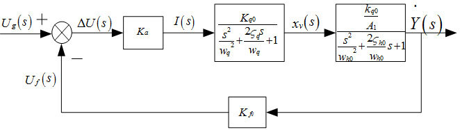
Bearing pressing speed control system is a nonlinearity and time-varying system. The pressing speed varies when the external load is changed. To obtain steady pressing speed, the parameters need to be adjusted frequently [16]. The conventional PID control algorithm is often cumbersome to set its parameters under such complicated conditions, and it does not achieve the desired effect on the bearing pressing speed control process. With the advancement of intelligent control technology, various control methods have emerged, such as fuzzy control and artificial neural network. Fuzzy adaptive control is based on fuzzy mathematics and does not require precise mathematical models, it is better for control of nonlinear systems [17, 18]. Combining the advantages of conventional PID control and fuzzy control, a bearing pressing speed controller is designed by fuzzy adaptive PID method to ensure the speed stability in the bearing pressing.
Speed controller structure design
The speed controller adopts two-input and three-output fuzzy PID control. The bearing press machine detects the current pressing speed value continuously, and the control system compares the current value with the set value to obtain the speed deviation
Speed controller structure.
Division of fuzzy space
The fuzzy controller cannot recognize precise input/output variables, so input and output variables need to be fuzzy variables. Generally speaking, the finer the division of input and output variables, the higher the control accuracy. However, it makes the algorithm more complex and impacts the response of the control speed [19]. According to the actual situation and the existing experience, the input and output variables are divided into seven levels, namely {negative big (NB), negative middle (NM), negative small (NS), zero (Z0), positive small (PS), positive middle (PM), positive big (PB)}, respectively to describe
Determination of fuzzy domain
The range of variables is the basic domain of variables. The basic domain of speed deviation
Determination of membership function
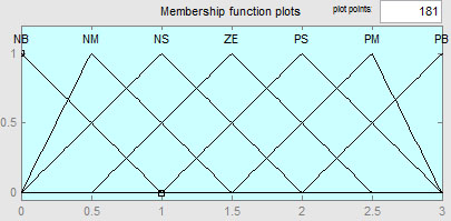
Trapezoid membership function, triangle membership function and Gauss membership function are three commonly used membership functions [20]. Compared with trapezoid membership function and Gauss membership function, the mathematical expression of triangle membership function is relatively simple, and its shape is just related to the slope of the straight line, which occupies less memory space during operation. Therefore, triangle membership function is widely used in fuzzy PID control. The input and output variables are all controlled by trigonometric membership function. The membership function curve of input/output variables is shown in Figs 7–10.
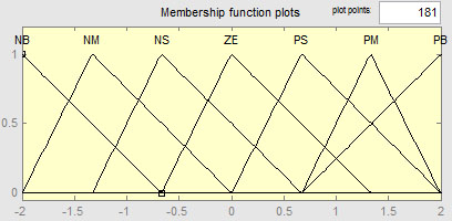
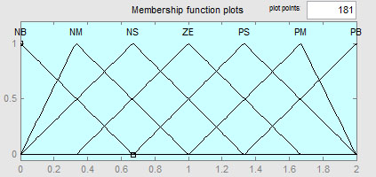
The speed deviation is serious when the system load is changed suddenly, therefore, the control system response speed needs to be increased. Moreover, the larger
Integration has the greatest impact on the final control result. The response speed of the system can be guaranteed by selecting appropriate integration. When the speed deviation is medium, the smaller
When the speed deviation is small, the values of
According to the above analysis, the fuzzy control rules of
fuzzy control rules

The solution to fuzziness is also called the anti-fuzziness process or the precision process. The commonly used accurate calculation methods mainly include the maximum membership function method, the gravity center method and the weighted average method.
Maximum membership function method
Maximum membership function method simply takes the largest membership degree element as the output value of the fuzzy set of all rule reasoning results. In the output domain, if there is more than one output value of the maximum membership function, the average value of all the outputs with the maximum membership is calculated, that is,
The gravity center method takes the gravity center of the area enclosed by the fuzzy membership function curve and abscissa as the output value of fuzzy reasoning, namely,
In contrast to the maximum membership function, the gravity center method has a smoother output reasoning control.
The output value using the weighted average method is obtained by the following formula,
In the pressing control system, the selection of coefficient
To verify fuzzy adaptive PID control of speed control of SCRBP, the simulation model of fuzzy adaptive PID controller is built. Fuzzy adaptive PID control simulation model is shown in Fig. 11. Fuzzy adaptive PID control results are also compared with conventional PID control.
Speed without load
The pressing speed rises rapidly to 5 mm/s after the press machine started. Therefore, the input signal of the control system is regard as a step signal. The step signal amplitude is set as 5. The initial value
Simulation model of bearing pressing speed control.
Conventional PID and fuzzy adaptive PID control results
Response curve of bearing pressing speed control. 1. Fuzzy adaptive PID curve; 2. Conventional PID curve.
Response curve of bearing pressing speed-control-system with sinusoidal interference signal. 1. Fuzzy adaptive PID curve; 2. Conventional PID curve.
From the curve value of Fig. 12, it is seen that fuzzy adaptive PID adjustment time is 0.5 s, while conventional PID adjustment time is 0.8 s. Fuzzy adaptive PID rising time is 0.2 s, and conventional PID rising time is 0.08 s. In terms of overshoot, the overshoot of fuzzy adaptive PID can be controlled to almost 0, while that of conventional PID is about 10%. The comparison results of fuzzy adaptive PID controller and conventional PID controller are listed in Table 4. Seen from the simulation results in Fig. 12 and Table 4, it is obvious that fuzzy adaptive PID controller shortens control time when the bearing pressing speed reaches the balance value, and the overshoot is very small.
Friction and extrusion force are often occurred in bearing press process, which make the press speed fluctuate irregularity, thus, it is difficult to obtain the actual load data in pressing process. In this paper, sinusoidal interference signal and step interference signal are added to the pressing speed control system of SCRBP to simulate the control effect of fuzzy adaptive PID and conventional PID when the load changes slowly or suddenly.
1) Speed with sinusoidal interference signal
The response curve of bearing pressing speed control system with sinusoidal interference signal is shown in Fig. 13, the magnification of the response curve is shown in 14.
Seen from Figs 13 and 14, after the sinusoidal interference signal of 1 Hz is added, the bearing pressing speed fluctuates up and down near the set speed, and the fluctuation amplitude is small. The control effect of conventional PID on bearing press speed is great with bigger fluctuation amplitude. Therefore, fuzzy adaptive PID is more suitable for the control of pressing speed system with sinusoidal interference signal.
Magnification of the response curve of the bearing pressing speed control system. 1. Fuzzy adaptive PID curve; 2. Conventional PID curve.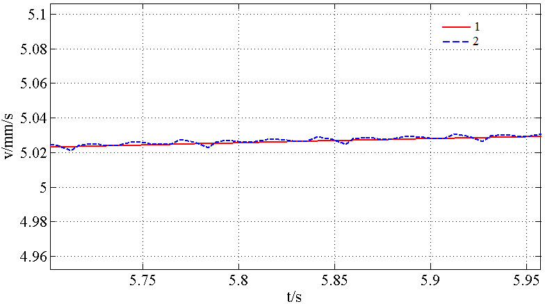
Bearing pressing speed control system with step interference signal. 1. Fuzzy adaptive PID curve; 2. Conventional PID curve.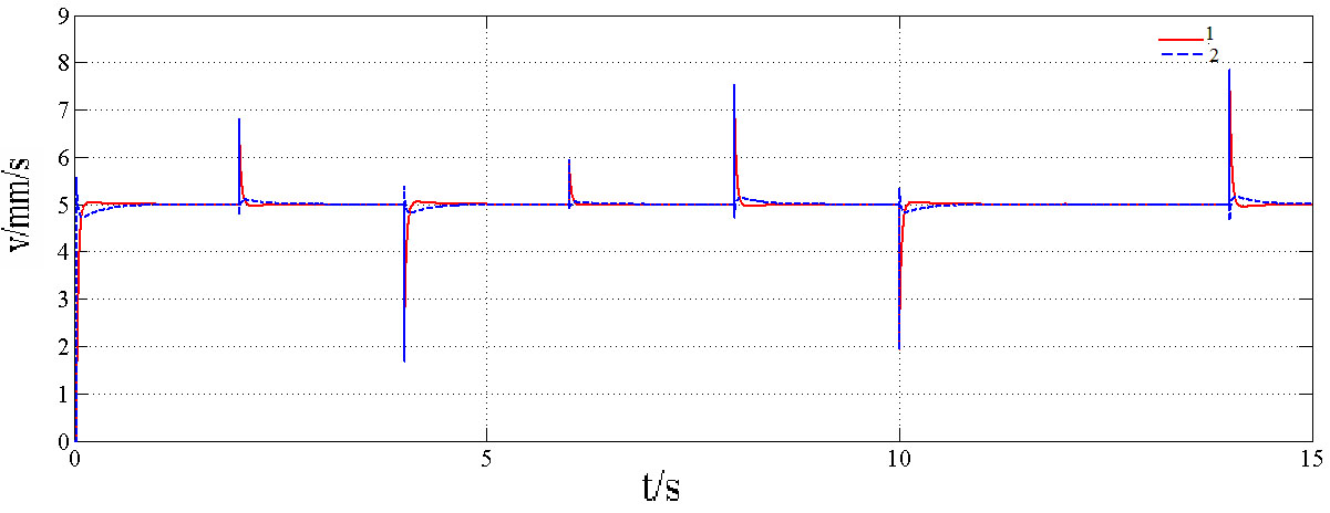
Enlarged view of bearing pressing speed control system. 1. Fuzzy adaptive PID curve; 2. Conventional PID curve.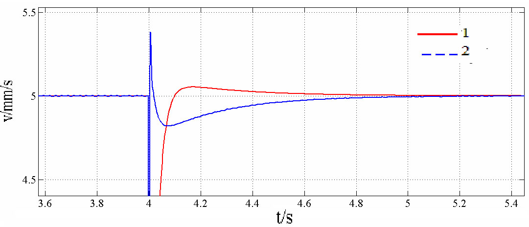
2) Speed with step interference signal
The speed curve of the bearing pressing speed control system with sinusoidal interference signal is shown in Figs 15 and 16.
It can be seen from the Figs 15 and 16, after the step interference signal is added, there is a sudden change in the pressing speed. Under the control of fuzzy adaptive PID or conventional PID, the bearing pressing speed can be stable near the set pressing speed. However, the speed change range and adjustment time are different. Fuzzy adaptive PID overshoot is smaller than conventional PID control, and the adjustment time of fuzzy adaptive PID is less than conventional PID control. Therefore, fuzzy adaptive PID controller is more suited to the bearing pressing speed control with the step interference signal.
A high-efficiency special ceramic roller bearing press machine (SCRBP) is developed to press two bearings at the same time. The bearing pressing speed has a direct influence on the bearing pressing accuracy. To obtain the rapid and stability bearing pressing speed, the speed control system mathematical model of the bearing press is built, and a fuzzy adaptive PID speed controller for bearing pressing is designed. The simulation controller model is built and simulated. It is compared with the controller of conventional PID. The simulation results show that fuzzy adaptive PID control shortens the adjusting time, and is better for speed control of SCRBP with step interference signal, which is beneficial to improve the pressing stability.
Footnotes
Acknowledgments
The authors would like to express heartfelt thanks to the technology research project of Hebei Provincial Department of Science and Technology (grant number 17211906D), the Nature Science Foundation of Hebei Province (grant number E2019402436), Key Laboratory of Intelligent Industrial Equipment Technology of Hebei Province (Hebei University of Engineering), Handan Key Laboratory of Intelligent Vehicles.