
Abstract
The need to implement high-speed Signal processing applications in which multiplication and division play a vital role made logarithmic arithmetic a prominent contender over the traditional arithmetic operations in recent years. But the logarithm and antilogarithm converters are the bottlenecks. In order to reduce the logarithmic conversion complexity, several works have been introduced from time to time for correcting the error in Mitchell’s algorithm but at the cost of hardware. In this work, we propose a 32-bit binary to the binary logarithmic converter with a simple correction circuit compared with existing techniques. Unlike the current methods that use the linear piece-wise approximation in the mantissa, we propose a weighted average method to correct the error in Mitchell’s approximation. The maximum error percentage from the proposed work is 0.91%, which is 16.9% of Mitchell’s error percentage.
Keywords
Introduction
In many applications like radio communications, audio, video, aircraft, and in a large number of compact mobile consumer goods, digital signal processing (DSP) thus becomes pervasive. With the growing demand for DSP, there has been a rising need for hardware distribution of binary multipliers and binary dividers that are quicker and more productive in the area. The use of logarithms simplifies the arithmetic computations in both binary and decimal, as in [1]. Logarithms were used to simplify multiplication, division, and powering operations to the stage of addition and subtraction, where powering operations are simplified to multiplication [2].
The exact method for calculating the logarithm involves storing the logarithmic tables in memory, and such approaches are highly-priced for speed and hardware. For a few applications like image processing and DSP applications, a trade-off can be rendered by raising the conversion’s precision to reduce the system’s delay and power consumption. To simplify the logarithm computations, [3] proposed an algorithm for calculating the estimated log2 of a binary word. Here, the author used a straight-line approximation of the logarithm function for intervals between the two potential powers. The logarithmic values of real and Mitchell are shown in Fig. 1. Mitchell’s algorithm is less complicated than the traditional method of storing logarithmic tables but at the inevitable inaccuracy cost. Several approaches have been proposed to decrease the inaccuracy in Mitchell’s algorithm. [4] algorithm divides the two potential powers into four intervals. Here the authors performed straight-line approximation in each interval. The coefficients of every line were chosen by the trial and error method. This method is used to minimize the inaccuracy in the subsequent approximation of the logarithm [5]. Often they used four sub-intervals and chose appropriate straight-line estimation to reduce the average error. These two methods are more successful approaches and also challenging to implement. [6] has used two straight-line approximations with less complexity, but the accuracy achieved by the error correction is not sufficient. To reduce errors, [7] has used two, three, and six subintervals. These methods are effective with an increase in the number of subintervals, which leads to an increase in effective area.
LOGN curve of real and Mitchell approximation.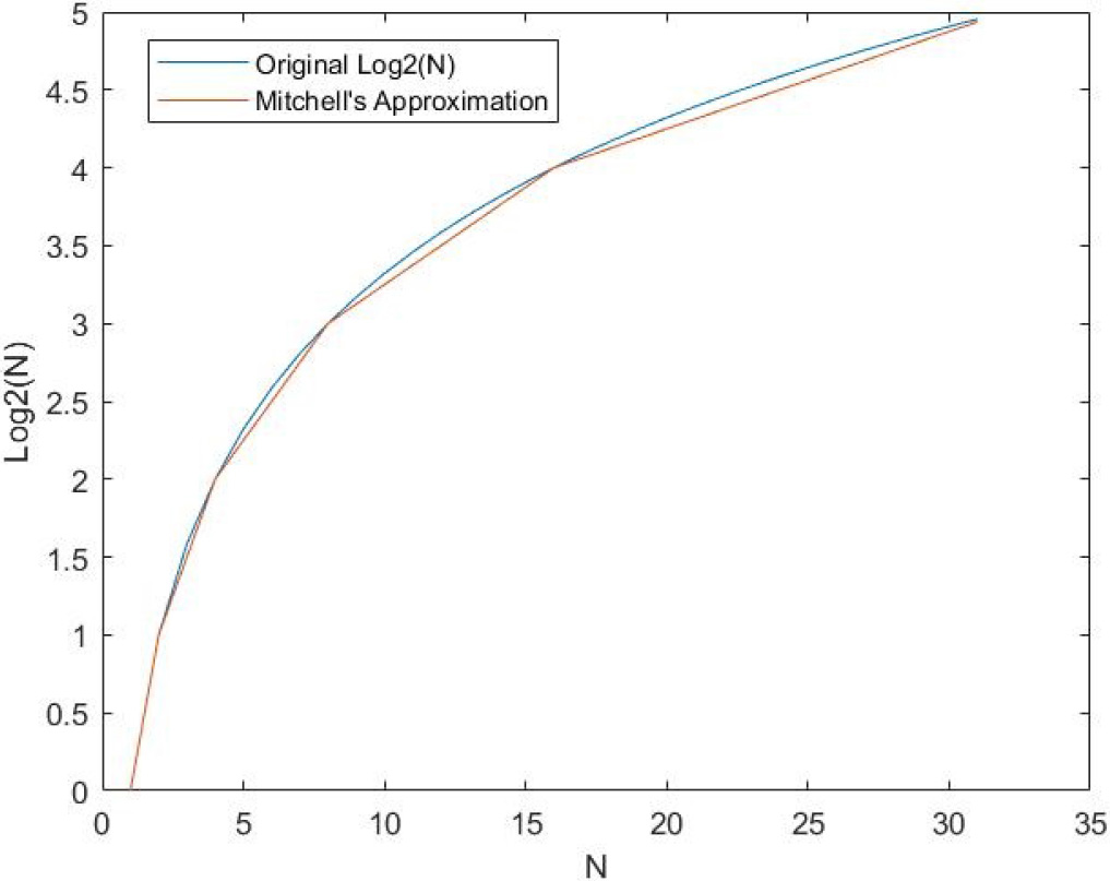
Mahalingam and Ranganathan [8] proposed an upgrade to Mitchell’s multiplier by an operand division method. The proposed architecture enhances the effectiveness of Mitchell’s multiplier by 44.7 percent. However, logic gates become doubles. Gandhi et al. [9] used estimated lead-one detectors to minimize the Mitchell multiplier area and power consumption. Using approximate lead-one detectors, the authors decreased Mitchell’s power consumption by 55%. However, there is a massive error in the multiplication of small numbers.
Kim et al. [10] have used bit truncation to make Mitchell’s multiplier design more potent. Authors reduce the logarithmic representation of multiplier inputs to use smaller barrel shifters. The proposed truncation greatly decreases the delay, power, and area compared to the original Mitchell multiplier, but at a higher error rate. Kim et al. [11] successfully solved the truncated Mitchell multiplier’s high error problem by adding an iterative truncated Mitchell multiplier. The iterative approach greatly increases precision at the expense of higher power consumption.
For the addition of the mantissa, which includes a small barrel shifter configuration, Liu et al. [12] use approximate truncated adders. Their multiplier has the same accuracy as the multiplier from Mitchell, offering at the same rate a lower power-delay device.
The iterative logarithm multiplier (ILM) was developed by Babic et al. [13] to improve the Mitchell multiplier’s accuracy. To improve the Mitchell multiplier’s accuracy, the iterative logarithm multiplier (ILM) [13] was developed by Babic et al. ILM is an inexpensive and easy multiplier that achieves arbitrary precision by an iterative process. ILM uses a simpler approximation of the product, unlike Mitchell’s multiplier. Simple ILM has a relatively high mean relative error of about 10% due to the product’s generalized approximation. The accuracy of the multiplier increases as the mechanism is iteratively implemented. The ILM design generates a relative mean error of around 1 percent with just one iteration for error correction. The desirable feature of ILM is the ability to perform each iteration simultaneously. This role made the ILM extremely useful in neural networks [14].
By constructing a truncated iterative multiplier (TIM), Ahmed and Srinivas [15] discussed the problem of sophistication in ILM. TIM supports the product approximation approach to ILM, but TIM truncates the product approximation terms to allow smaller adders and shifters, unlike ILM. Truncation succeeds in a major reduction in the chip region than ILM, but it doesn’t provide a latency change. TIM produces a smaller error compared to ILM from an accuracy point of view.
In the works described above, there is adequate research on logarithmic multipliers. In these works, all authors aim to change the Mitchell logarithmic multiplier architecture and have tried to reduce the error but failed to minimize the errors due to logarithmic and antilogarithmic converters. Therefore, modifying the logarithmic and antilogarithmic converters is the most suitable approach to reducing conversion errors, and these corrections are reflected in all arithmetic operations. Hence, in the present paper, we have proposed logarithmic converters with less complexity and less area.
In this work, a novel approach to design a 32bit binary to binary logarithmic conversion based on weighted average correction of Mitchell’s algorithm for low power applications is proposed. The main contributions to this paper can be summarized as follows:
This paper presents a new error-correcting circuit to improve Mitchell’s algorithm’s accuracy based on the method of weighted average. The Error-correcting circuit corrects the mantissa term based on the characteristic part of the logarithmic conversion. Unlike the existing methods, the proposed error correcting circuit will remain simple irrespective of the number of bits used for correction in the mantissa. Next, the paper shows that the proposed logarithmic conversion provides better offsets than conventional precise scaling methods.
This paper has the following texture: The related work is discussed in Section 2. The logarithmic converter (LC) is summarised in Section 3. Section 4 elaborates on the proposed work. Section 5 contains the experimental results with error and hardware analysis. Finally, Section 6 brings the paper to a close.
The logarithmic conversion method is of two types:
Techniques using the lookup tables and interpolation. Methods that are based on the Mitchell algorithm, which calculates the logarithms by shifting and counting operations.
Although memory is used in lookup table-based approaches, Mitchell’s algorithm works without memory but with a loss in accuracy. As a result, several scholars have offered ways to increase Mitchell’s algorithm’s accuracy. The taxonomy diagram, as shown in Fig. 2, lists the numerous related works in logarithmic conversion. In the following section, we’ll go through some of these ways in more detail.
Taxonomy of related work.
The conventional logarithmic conversion solution uses entire logarithm value tables retained in memory, which is unreliable in processing specifications. Consequently, some researchers discussed the possibility of utilizing smaller lookup tables and use interpolation methods to compensate [16, 17, 18, 19, 20]. The purpose was to determine LUT sizes, which correspond to different logarithmic accuracy levels and trading on precision versus overhead muscle. Attempts to minimize the volume of memory to store lookup tables have a keen interest in Mitchell’s algorithm, terminating the need for lookup tables completely.
Base two logarithm of binary number using Mitchell’s algorithm
In [3] base two logarithm of binary number is as follows: Let us consider a binary number
Where,
If
Let the term,
As,
By applying logarithm on both sides,
Comparison of base two binary logarithms of exact and Mitchell algorithm
Here, the term
The error in the approximation is equals to actual logarithm minus approximate logarithm. Therefore,
For example, Let
In [3] suggests that the calculation error is because of a mantissa. Here the error will be in the interval [0, 0.08639]. It can be observed that the error percentage is always positive and is in the range of 0 to 5.3605%. Many research have attempted to reduce this error percentage by using a single estimate in different ranges or applying a counterbalanced component to Mitchell’s output.
Combet et al. correction
In [4], the interval [0, 1] of mantissa
The Combets et al. method lowered the average error percentage of the logarithmic conversion from 5.36% in the Mitchell method to 0.451%. However, the technique used by Combet et al. has a significant problem with the large overhead hardware. Another significant problem with this method is that the coefficients are not two potential powers.
In [5] has divided the mantissa m into four regions, each region has a separate correction coefficient. In [5], Hall introduced a set of correction parameters intending to reduce mean square error. The correction parameters of Hall’s method for four sub-regions are given below.
Where
[7] constructed correction coefficients, which require small and fast circuitry while maintaining accuracy near the method used by Hall et al. Three specific correction approaches were suggested with varying hardware sophistication and precision, focused on equations for two, three, and six regions. The complexity of the circuit increases with an increase in the number of sub-regions. The modified parameters use the mantissa’s first three significant bits. Also, the coefficients are limited to the two powers. The equations of the Abed’s et al. algorithm corrected by 2-region is as follows:
Where,
The complete implementation of 32-bit binary to binary logarithmic conversion implemented using Mitchell’s algorithm along with the error-correcting circuit is presented in Fig. 3. Here, the logarithmic converter (LC) uses a leading one detector (LOD) circuit, a logarithmic shifter, 32
Existing 32 bit binary to binary logarithmic conversion.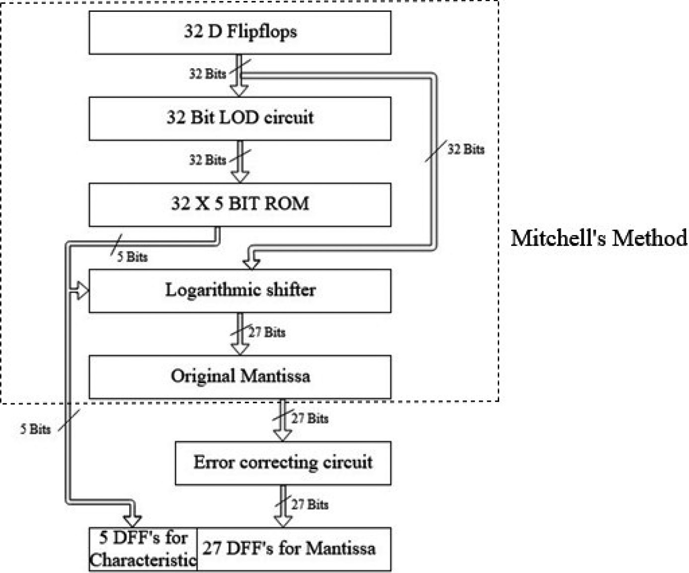
The 32-bit input word is given to the LOD circuit and a decoded active-high 32-bit output is generated [7, 21, 22, 23]. The 32 Bit Lead One Detector (LOD) identifies the most significant one in the given input. The LOD circuit sets the most significant one position as active high bit and other bit positions to zero. For example, N
32
5 bit ROM
The 32
32 bit logarithmic shifter
The logarithmic shifter is the important piece in binary logarithmic converters as it supplies the mantissa part of the final value. An N-bit logarithmic conversion needs a logarithmic N-bit shifter to rotate the data from 0 to N-1 [11, 24, 25]. Here, the output is identical to the input term, which is shifted by a number of positions defined by the leading one position, and the direction of shifting is from the LSB to the MSB. In the above example, the shifter has to shit 7 bits as the characteristic is equaled to 7 and the output of the shifter is (101101100000000000000000000)
The proposed error-correcting algorithm
Depending on the provided logarithmic conversion methods, a trade-off exists between the precision obtained, delay, and hardware required for the correction circuit. Both [4, 5] is focused on using all the bits in the mantissa for modification. They were 27bits in the 32-bit logarithmic converter; thus, it requires a 27-bit error correcting circuit. Furthermore, these algorithms require mantissa to be multiplied with different slopes, which necessitates the addition of four additional blocks, one for each of the four regions. The binary logarithm’s great precision, which comes from Combet’s technique and Hall’s method systems, comes at the cost of speed, high power consumption, and hardware complexity. The correction circuit formed by SanGregory, unlike Combet’s method and Hall’s method, is portable and quick. It only uses the four most significant bits of the mantissa for approximation; nevertheless, it is less efficient than the other methods in terms of accuracy.
The main aim of this paper is to propose an algorithm for binary logarithm correction. This can be achieved with the circuits that have a low conversion error rate. In the proposed algorithm, it is suggested to use a few bits from the mantissa. The algorithm also offers to use the logarithmic value characteristic to choose the correction term for correction in the mantissa. For the reduction of error in Mitchell’s algorithm, the weighted average method is proposed. In this algorithm, the numbers are divided into successive two powers, as illustrated in Table 2.
Illustration of proposed algorithm
Illustration of proposed algorithm
Let us consider a number
In each region, the deviation of Mitchell’s value from the exact value is calculated. The average deviation in each region is also calculated by excluding the terms with powers of two (
So Eq. (22) becomes
The average values of the deviations are moved to the most significant one and represented as the characteristic of the logarithmic value, as shown in Table 3.
Block diagram of proposed logarithmic conversion circuit.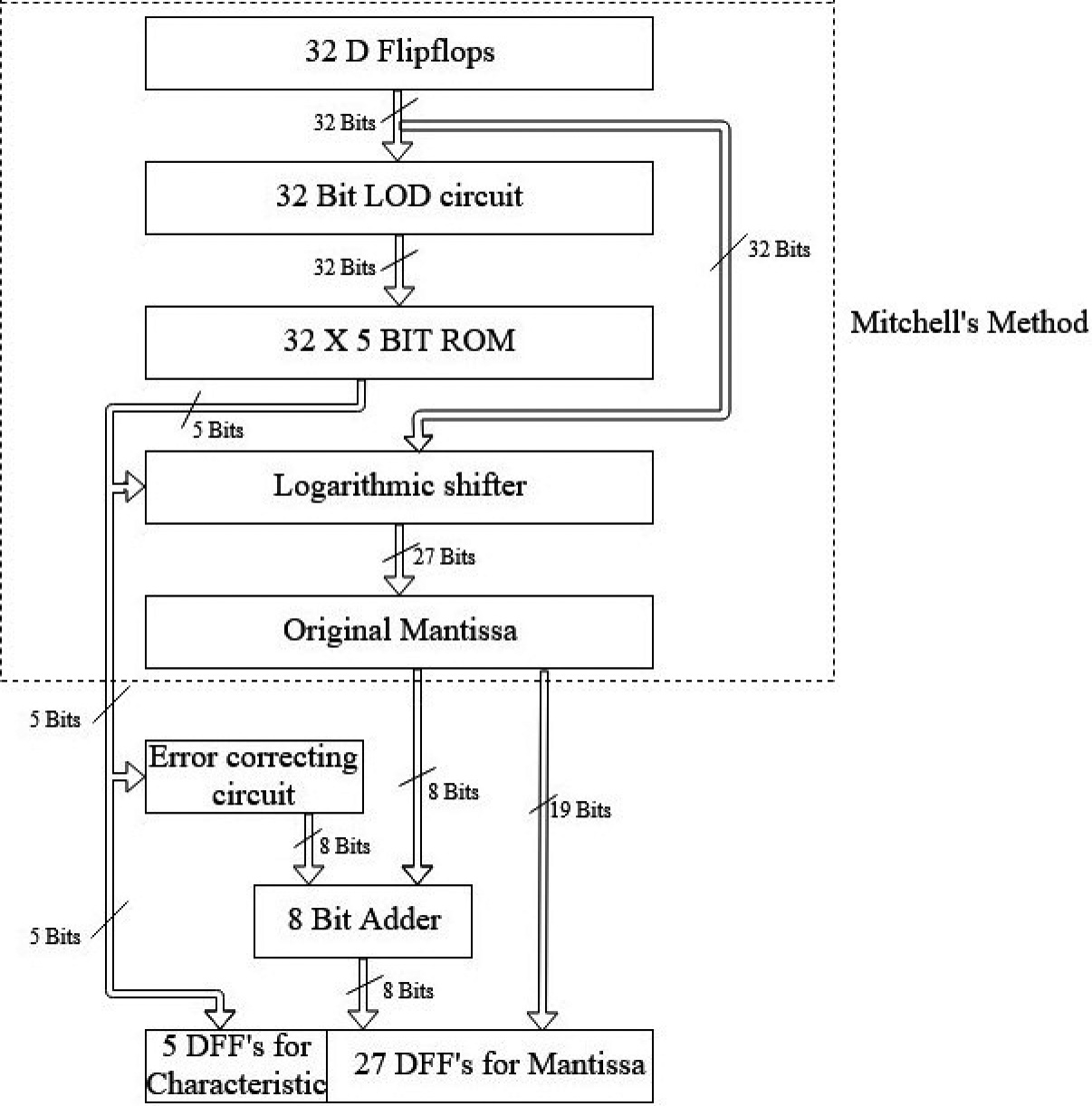
Correction term for different characteristic values
Illustration of error correcting block.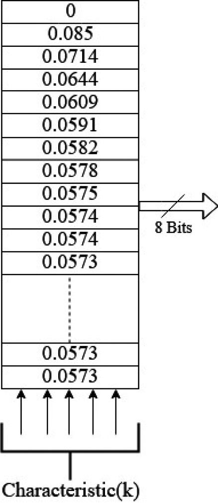
Illustration of an example using the proposed method.
Comparison of the proposed approximation with exact and Mitchell’s approximation.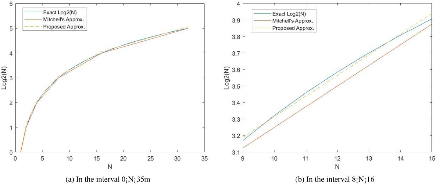
Comparison of the proposed approximation with exact and Mitchell’s approximation.
The correction terms are chosen using the characteristic (k), which is then appended to the mantissa’s most significant eight bits. Table 2 shows an illustration of the proposed algorithm and an example illustration is shown in Fig. 6. The block diagram of the 32bit binary to a binary logarithmic circuit with the proposed algorithm is illustrated in Fig. 4. Unlike the algorithms mentioned above, the recommended error correcting circuit receives the input from the characteristic of the logarithm. The error-correcting block is illustrated in Fig. 5. Here, the correction terms in Table 3 are stored in the ROM. These correction terms are selected using 32
To demonstrate the value of the proposed logarithmic converter, we compare its error % and hardware metrics to those of several estimated logarithmic converters in the present state of the art. These logarithmic converters include [3, 4, 5, 7]. As in the recent literature, works mostly focused on Mitchell’s logarithmic technique based multipliers [8, 9, 10, 11, 12, 13, 14, 15] and they tried to decrease the error in multiplier result. Still, they haven’t focused on logarithmic and antilogarithmic converters. This made the authors restrict their comparisons of proposed logarithmic conversion to Mitchell’s techniques [3, 4, 5, 7]. The main findings of the proposed work are as follows:
Comparison of errors in binary logarithm algorithms
Comparison of errors in binary logarithm algorithms
Hardware performance.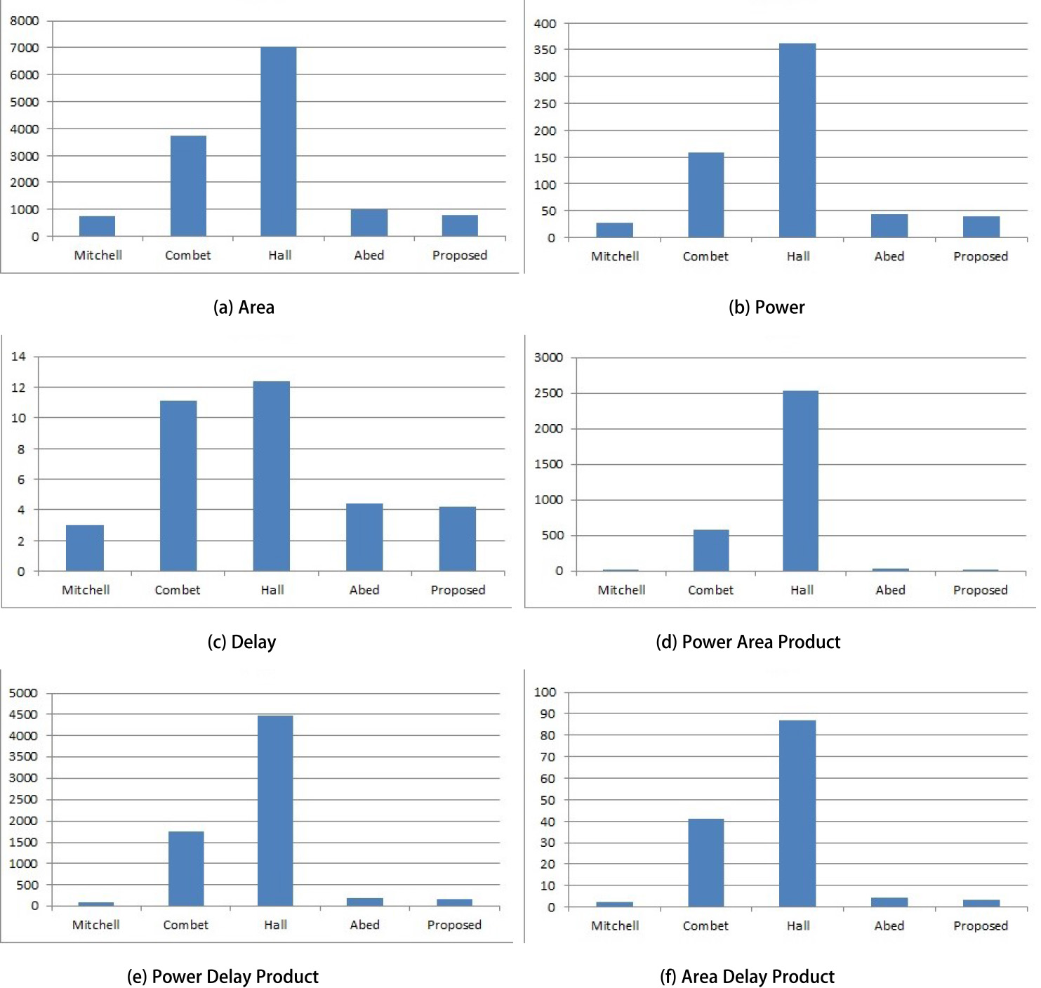
Comparison of Hardware consumption of different logarithmic converters
Comparison of hardware performance metrics of different algorithms vs peak error percentage.
The ROM based error-correcting circuit made the logarithmic converter’s implementation simple and improved the logarithmic converter’s speed compared with other circuits. The area of the proposed logarithmic converter is reduced when compared to other proposed algorithms. The proposed logarithmic conversion consumes less power when compared with the other methods. The maximum error in the proposed work is 0.91% (
The above-stated findings are explained briefly in the rest of the section.
The maximum error percentage achieved by using the proposed method ranges over
Hardware analysis
The 32-bit Logarithmic converter using different algorithms is described using Verilog HDL at the gate-level, and the corresponding designs are synthesized using a CADENCE 6.1 EDA tool with 90 nm CMOS technology. The hardware performance metrics such as area occupied, power consumption, critical path delay, area delay product (AD), power delay product (PD), power area product (PA) are evaluated for different algorithms used for logarithmic conversion. These performance parameters are listed in Table 5. It is observed from the tables that the proposed method occupies 78.45%, 88.6%, 19.2% less area, consumes 75.4%, 89%, 10.3% less power, and 62%, 66% and 5% faster when compared with Combet et al. [4], Hall et al. [5], and Abed et al. [7] respectively. The comparison of hardware performance metrics with different algorithms are shown in Fig. 9. Figure 10 shows the comparison of different algorithms’ hardware performance metrics with respect to the peak error percentage. From the above results, it can be observed that the proposed logarithmic converter consumes less power and occupies less area along with less peak error when compared with other algorithms. The proposed method serves as the best alternative in the areas where low power and fast logarithmic converters are used.
Conclusion
Simple error correcting circuit is used to create a 32 bit binary to binary logarithmic converter in this paper. We partitioned the numbers as powers of two in the proposed approach and estimated Mitchell’s deviation from the actual outcome. The weighted average of deviations in each partition is used to correct the terms in Mitchell’s output, making the error percentage reduce from 5.36% in Mitchell’s to 0.91%. The logarithmic converter is less difficult and easier to implement than existing approaches since the correction terms are stored in ROMs. When hardware complexity is taken into account, the proposed method appears to be the best way among the existing error-correcting algorithms.