
Abstract
Aiming at the problems of low control accuracy and long control time in traditional UAV automatic takeoff ground roll control method, a CFD based UAV automatic takeoff ground roll control method was proposed. Firstly, the flow field calculation formula is defined in the inertial coordinate system, and the rotor flow field generated between UAV and automatic take-off ground roll is solved by CFD method. Then according to the value, the unmanned aerial vehicle (UAV) rotor flow field flow rate from the air spring force, tire spring force, buffer damping force and under the action of ground support, analysis the stress of the roll on the ground, finally on this basis, through the pitching Angle and angular rate control design protection design, airspeed protection design complete automation design, realizes the unmanned aerial vehicle (UAV) automatic take-off and roll control. The simulation results show that the control accuracy of the proposed UAV automatic take-off ground taxiing is 99.5% and the control time is less than 5 s. This method has good control performance and is worth popularizing.
Introduction
Unmanned aerial vehicle (UAV) is an unmanned aerial vehicle, short for reusable aircraft, which is currently widely used in military and civilian fields [1]. Compared with other ordinary aircraft, the biggest feature of UAV is that it does not need to consider the life support system, or even the cockpit, which relaxes the restrictions and requirements of flight quality, so that the flight control system maximizes the pursuit of aerodynamic efficiency and control efficiency [2]. However, since the UAV does not have a pilot to drive it, it can only use the automatic control system to replace the pilot, which leads to its lack of decision-making ability and flexible driving control ability. At present, the existing immature airborne navigation control equipment is still unable to compare to the pilot [3]. Overcoming the shortcomings of UAVs and giving full play to the advantages of UAVs has become the focus of the development of today’s UAV systems. The automatic take-off and ground-roll control technology is an important automatic control technology in the field of drones. The unevenness of the runway, the different ground conditions of the left and right wheels, the slight difference in the wheel size, and the interference of the wind will cause the drone to roll on the ground when it takes off automatically. When turning, the lateral offset and lateral speed are generated, and there is a danger of deviating from the runway. The application of this technology can help the UAV to achieve ground roll and automatic take-off [4]. In recent years, this technology has also been actively studied at home and abroad.
With the development of computer technology and control theory, the automatic take-off and ground roll control technology of UAVs at home and abroad has shown many new development directions. Li et al. [5] take the take-off and operation test of a certain type of rhombus-wing UAV as the starting point, analyzes the problems faced by the UAV with this layout and the characteristics of the rhombus-wing layout, and designs a control method based on backstepping. The control method takes into account the interference caused by the take-off conditions and the influence of the nonlinear factors of the UAV itself, and controls the heading and roll of the UAV taking off and rolling. The simulation results show the effectiveness of the proposed control method, but it has poor stability and poor control performance. Fu et al. [6] aimed at the problem that high-speed UAVs are prone to skidding and rushing out of the runway when taxiing on the ground. The main factors and mechanisms of sideslip are studied, and the dynamic model of the UAV’s taxiing section is established. Based on the correction control, the sideslip angle feedback is introduced into the heading inner loop control, and the braking control strategy is optimized at the same time, and a safety control strategy that can effectively suppress large sideslip is proposed. The coasting test shows that the control strategy can effectively suppress improper braking. And the sideslip caused by strong crosswinds can improve the anti-skid performance of the UAV during taxiing, and achieve better application effects in the taxiing test. However, when this method is applied, the control time is long, and it is difficult to achieve the best control effect. Zhang et al. [7] proposed a dynamic simulation method for the roll-off stage of the wheeled take-off and landing UAV. Taking the wheeled take-off and landing UAV as the research object, according to the mechanical characteristics and geometric relationship of the landing gear, the landing gear is equivalent to a wheeled take-off and landing UAV. Models such as UAV fuselage, landing gear, engine, steering gear, and control system are integrated in MATLAB/Simulink, and the entire process of UAV taxiing and take-off is simulated. Although this method achieves good control effect in the simulation process, it does not consider the interference of the external environment on the control of the UAV, and the application effect is not good.
However, the above three methods have low control accuracy for the automatic take-off and ground roll of the UAV, and the control time is long. To this end, this paper proposes a CFD-based automatic take-off ground roll control method for unmanned aerial vehicles. The CFD method is used to complete the solution of the rotor flow field between the unmanned aerial vehicle and the automatic take-off ground roll, and then according to the obtained flow field flow value, fully analyze the external interference of the UAV in practical applications, and based on this, design the UAV’s pitch angle control, angular rate protection, airspeed protection, etc., to realize the automatic launch of the UAV Ground roll control. It is verified by simulation experiments. The effectiveness of this method solves the problems existing in traditional methods and lays a foundation for the development of UAVs in my country.
Control method for automatic take-off and ground run of unmanned aerial vehicle
Calculation of UAV rotor flow field based on CFD
When the drone takes off automatically, because the wing is stationary, the rotor wake directly hits the wing with an inflow angle of 90, which causes a serious three-dimensional blocking effect. In addition, due to the high symmetry of the tilt-rotor aircraft, the downwash of the left and right rotors hits the wing and spreads around. The air flow spreading inward along the span of the wing meets at the center axis of the fuselage and turns. It moves upward, and then is sucked by the paddle, forming a “fountain” effect unique to tiltrotor aircraft [8]. When the tiltrotor is flying close to the ground, due to the existence of the ground, the downwash of the left and right paddles hits the ground and spreads along the ground. Then the two airflows meet at the central axis of the lower fuselage and move upwards. Make the flow field changes of the whole machine more complicated. Therefore, the CFD calculation method is used to calculate the rotor flow field generated between the UAV and the automatic take-off ground roll [9].
For the steady state rotor hovering flow field, it can be regarded as a steady flow in the blade rotating coordinate system. In this paper, the flow field calculation formula is defined in the inertial coordinate system to obtain the rotor flow field calculation formula during hovering:
In the formula,
Solution vector calculation expression:
Solution vector calculation expression:
Viscous flux calculation expression:
In the formula,
According to the calculation formula of the rotor flow field established above during hovering, first, the calculation area is approximately discretized into a finite number of non-overlapping grids, and a series of non-overlapping control volume elements are taken in a small area around each grid node. There is only one grid node inside each control body unit, and then set the flow field to be solved on the unit grid node, and then use the law of conservation of momentum to integrate each control body unit. Set the discrete format of the control body unit, and finally solve the calculation formula of the rotor flow field when hovering, and the numerical solution of the flow is obtained as:
In the formula,
Rolling on the ground is the final stage of the drone’s flight mission. When rolling on the ground, due to the existence of a large number of non-linear systems such as buffers, brakes, wheels, etc., the motion characteristics of the UAV cannot be linearized like the approach and landing stage [11]. Therefore, in order to determine the control gain of the ground sliding, it is necessary to analyze the ground sliding response under the action of the air spring force and the tire spring force, the buffer damping force and the ground support force based on the flow value of the UAV rotor flow field obtained above. The specific situation is as follows:
(1) Air spring force and tire spring force
According to the composition principle of the oil-type shock absorber, the air spring force
In the formula,
The linear or non-linear relationship between tire spring force and stroke can also be determined experimentally. However, in the complex and closed system of the ground model, it is impractical to obtain the compression stroke of the shock absorber or the deformation of the tire alone. In engineering, experiments are often used to obtain the corresponding relationship between the total compression of the landing gear and the total spring force. When the total compression of the landing gear is obtained by calculation, the sum of the air spring force and the tire spring force can be obtained by looking up the table [12].
(2) Buffer damping force
The damping force
In the formula,
(3) Tyre damping force
The damping force of the tire is also related to the compression rate of the tire, namely:
In the formula,
Schematic diagram of UAV taking off.
According to the analysis results of the above-mentioned ground rolling force, the design of the automatic take-off control law is completed through the design of pitch angle control, angular rate protection design and airspeed protection design. For conventional wheeled take-off and landing UAVs, the take-off process is relatively fixed. From the time the UAV receives the take-off instruction, until it finally reaches a safe altitude, it can be divided into three stages [13]. A typical wheeled drone take-off and landing process is shown in Fig. 1.
(1) In the three-wheel skating section, the UAV starts to accelerate from a stationary state. This stage is called the three-wheel skating section before reaching the speed of raising the front wheels. The pitching moment balance requires the drone to reach the speed of lifting the front wheels in the shortest time. At the same time, during the taxiing process, the drone needs to maintain a certain amount of load on the front wheels to ensure that it has a certain correction ability. Make the drone run along the centerline of the runway [14].
(2) In the two-wheel skating section, when the preset speed of raising the front wheels is reached, the UAV starts to enter the two-wheel skating section. The longitudinal control law gives the command signal to raise the front wheel, and the longitudinal head-up torque of the drone increases, so that the front wheel leaves the ground. At this stage, it is necessary to ensure that the rear wheel does not scratch the ground during the process of raising the front wheel of the drone. Or if the head is raised too sharply, the effect of the control law should make the attitude of the UAV be pulled up quickly and steadily, and the overshoot should not be too large.
(3) In the climb phase from the ground, when the UAV rolls to a certain speed, the lift of the aircraft is greater than gravity. At this time, the rear wheels of the UAV begin to lift off the ground, and the aircraft enters the climb phase from the ground, maintaining a certain pitch climbing; before climbing to a safe altitude, ensure the smooth switching of the flying mechanism, including the retracting of the landing gear, the return of the UAV elevator, etc., and the airspeed needs to be restricted to ensure that it is in the required flying within range [15].
During the take-off phase, the UAV needs to reach the speed of raising the front wheels in the shortest time and the fastest speed. The longitudinal elevator control channel of the UAV controls the attitude during the entire take-off phase. During the taxiing phase, the elevator channel needs to be ensured. A certain front wheel load, when the speed reaches the speed of raising the front wheel, the drone’s elevator needs to be pulled out of the rudder to pull up the drone’s attitude, so that the drone will enter the two-wheel skating stage from the three-wheel skating, until the drone turns climb, and finally reach a safe altitude. The UAV has a large pitch angle rate at the moment when the front wheel is raised. The instantaneous increase in the angle rate has a great influence on the pitch angle controller of the UAV. If the angle rate is too high, the damping term of the controller is too large. Brings additional head-down moment, which affects the attitude of the UAV. In addition, an instantaneous increase in the angular rate will easily cause a large overshoot of the UAV’s pitch angle, causing the pitch angle to oscillate. Therefore, it is necessary to adjust the pitch angle rate to a certain extent.
(1) Pitch angle control design
The take-off control surface of the UAV includes elevator and throttle. According to the calculation of take-off performance, the elevator channel maintains the zero position in the three-wheel skating section, and is connected to the pitch angle controller in the two-wheel skating section, while ensuring the protection of the pitch angle rate. Continue to ensure the pitch angle control during the off-ground take-off section, while protecting the airspeed; the UAV’s throttle channel maintains a constant throttle state during the entire take-off process to avoid frequent switching caused state fluctuations. The pitch angle control law of UAV consists of three parts, among which the pitch angle proportional term is the main control term of the control law, and the integral term of the pitch angle has two functions in the control law. One of the initial values of the integral can be the control law an additional front wheel rudder surface is provided to ensure that the UAV can be pulled up smoothly. The second integral term can automatically trim the UAV during the climbing process and eliminate the error value of the pitch angle. According to the robust servo LQR method introduced in Chapter 2, we obtain the state value
(2) Angular rate protection design
The UAV needs to protect the angular rate at the moment when the front wheel is raised to prevent the front wheel from being raised too violently, causing a large overshoot of the pitch angle, causing the UAV to oscillate in the pitching attitude during two-wheel skating. The tail may wipe the ground. The angular rate protection of the UAV is realized by correcting the pitch angle command. In this process, it is necessary to ensure that there is a certain limit on the pitch angular rate, and at the same time it cannot affect the instantaneous pitch moment of lifting the front wheel. The mathematical expression is:
In the formula,
In the selection of the time parameter
(3) Airspeed protection design
The airspeed protection control law uses the proportional control of the airspeed to correct the pitch angle control command with the error of the indicated airspeed. The mathematical expression is:
The airspeed protection control law actually restricts the UAV to fly within the specified airspeed range by adjusting the attitude and then changing the climb trajectory angle. When the UAV’s airspeed is greater than the upper bound of the specified airspeed range, the UAV uses its posture to increase the gravity component in the longitudinal direction of the body axis to counteract the effect of the engine and slow down the UAV’s speed; when the airspeed of the aircraft is less than the lower bound of the specified airspeed range, the UAV increases its airspeed by reducing the pitch attitude and the longitudinal component of gravity on the axis of the aircraft. By adjusting the airspeed protection control law through the root locus, the appropriate control parameters can be finally obtained.
In order to verify the performance of the CFD-based UAV automatic take-off ground roll control method in practical applications, a simulation experiment analysis is carried out. The basic parameter settings of the UAV are shown in Table 1.
Basic parameter settings of UAV
Basic parameter settings of UAV
Comparison results of the control accuracy of the three methods.
According to the above-mentioned basic parameter settings of UAVs, the CFD-based UAV automatic take-off ground roll control method proposed in this paper is adopted, and Reference [5] proposed a diamond-shaped wing UAV take-off roll control method based on the anti-step control method and Reference [6] proposed an anti-skid control method for the UAV’s taxiing section, and compared and analyzed the control accuracy of the UAV’s automatic take-off and ground taxiing.
According to Fig. 2, it can be seen that the control accuracy of the CFD-based UAV automatic take-off and ground roll control method proposed in this paper reaches 99.5% accuracy, while the control accuracy of the methods in Reference [5] and Reference [6] is up to 72.3%. The method in this paper is superior to the two comparison methods, and can be used to achieve high-precision automatic take-off and ground roll control.
In order to further verify the effectiveness of the method in this paper, the CFD-based UAV automatic take-off ground roll control method proposed in this paper, and Reference [5] proposed a diamond-shaped wing UAV take-off roll control method based on the anti-step control method and Reference [6] proposed an anti-slip control method for the UAV’s taxiing section, and compared and analyzed the control time of the drone’s automatic take-off and ground taxiing. The comparison result is shown in Fig. 3.
Comparison results of the control time of the three methods.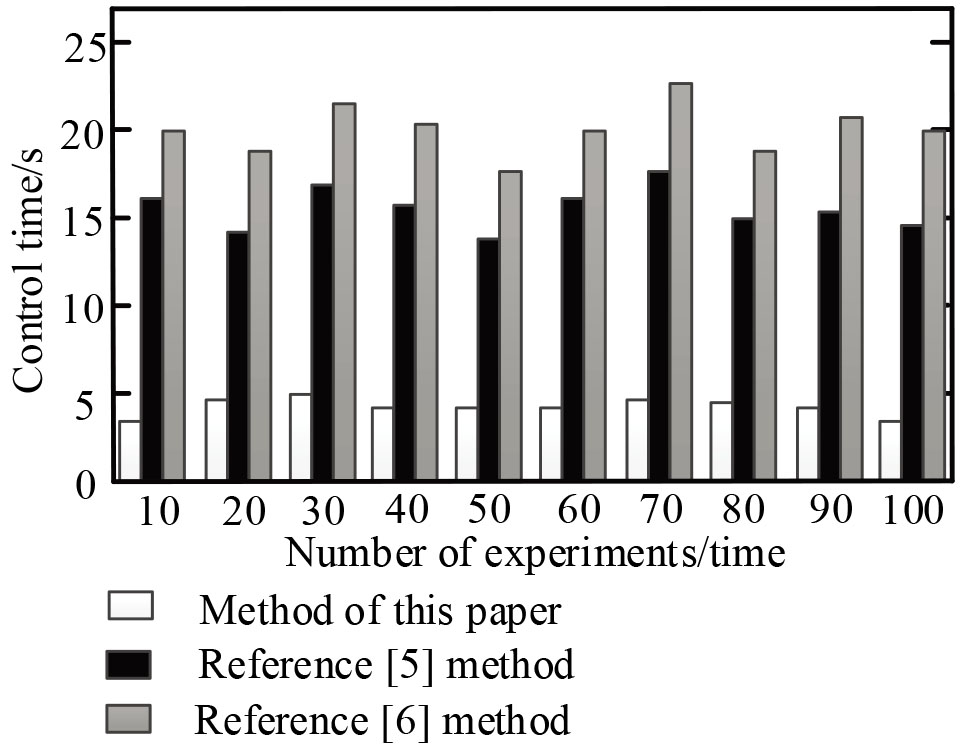
According to Fig. 3, the CFD-based UAV automatic take-off and ground roll control method proposed in this paper takes less than 5 s, while the control time of the method in Reference [5] and Reference [6] is between 14 and 23 s. The time of automatic takeoff and ground operation control is short, which is better than the comparison method.
For UAVs, a complete flight process includes take-off section, air cruise section and automatic landing section. Compared with the air cruise section, the automatic take-off and landing phases of the UAV have higher risks and hidden dangers. According to practice, it has been shown that although the take-off and landing time is short, these two phases are the most likely flight phases for accidents. Therefore, the control technology research of take-off and landing has always been one of the key research focuses in flight control. For conventional drones with the first three-point layout, automatic take-off refers to the entire process of the drone running on the runway and accelerating until it takes off and climbs to a safe height. This is a flight from a limited space to an infinite space. The main difficulties embodied in the process include high risk, complex process, and difficult control technology. For the UAV itself, the UAV has many state constraints during the take-off process. For example, in the process from the taxiing section to the climbing section, it is necessary to ensure that the pitch attitude and angular rate of the UAV are within a reasonable range. Inside, prevent the tail from rubbing the ground, and at the same time, pay attention to controlling the distance and time of the drone to ensure that it gets off the ground and enters the climbing section as quickly as possible. Take certain protection to prevent it from exceeding the boundary and causing a certain influence on the attitude; in addition to its own factors, the external environment also has a great influence on the take-off process. Based on this, this paper proposes a CFD-based automatic take-off and ground roll control method for UAVs. The simulation experiment test verifies that the control accuracy of the control method proposed in this paper reaches 99.5%, and the control time is less than 5 s, which is better than the comparison method and has more advantages. High precision and shorter control time can improve the control effect and control efficiency of the UAV’s automatic take-off and ground operation. Although this paper has achieved certain research results, its simulation of the outside world is still insufficient. Next, the interference of the external environment on the operation of the UAV will be further considered and the system will be optimized.